
About the post
I want to continue my series about light, gesture, motion and distance sensors with this post about UV sensors, i.e. sensors for ultraviolet radiation. A summary of the series can be found here.
First of all, I will briefly mention the definition of UV radiation. Then I’ll deal with the most commonly used UV sensors or the modules based on them:
- Guva-SD12SD
- UVM-30A (only briefly mentioned)
- ML8511
- VEML6075
- SI1145 (GY-1145)
The first three UV sensors or sensor modules have only one analog output. They are therefore easy to control with microcontrollers. The other two, on the other hand, are addressed via I2C. They are much more complex, so it is a good option to use libraries. There are also good tutorials about them, which I will refer to accordingly.
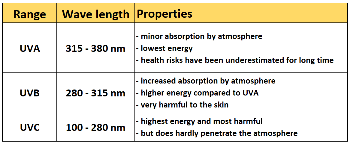
UV radiation
You find the ultraviolet light next to the spectrum of visible light in the short-wave range. According to the traditional definition, UV radiation extends over wavelengths from 100 to 380 nanometers. Within this range, there are areas that have quite large differences in their proportion in sunlight, absorption in the atmosphere and physiological effect. For this reason, UVA, UVB and UVC have been defined. UVB radiation is mainly responsible for sunburn. UVA radiation, on the other hand, does not cause sunburn, but has long been underestimated in terms of its harmful effect. Natural UVC radiation is scarce on the earth’s surface.
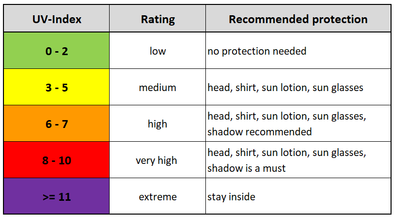
The UV index
The UV index is likely to be known to most. It was introduced as a dimensionless unit to quantify the effect of the sun’s UV radiation on the body. The sensors which are discussed here can only deliver approximate UV index values derived from calculations based on the measurement data. Since UV radiation has a different effect on the body at different wavelengths, the radiation intensity must be measured correspondingly per wavelength range and then weighted. A simple sensor cannot do that. The calculations are based on the assumption of a constant intensity distribution. On Wikipedia you can find more information about UV radiation and the UV index.
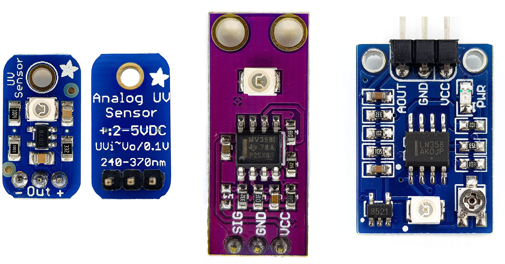
Guva-S12SD
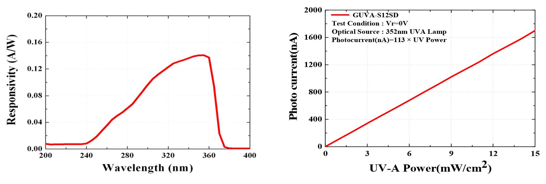
The Guva-S12SD sensor itself is a UVA and UVB sensitive photodiode. A data sheet is available here or here. Curiously, it is described as UVA sensor in one data sheet and as UVB sensor in the other. However, it actually covers both areas (see chart). The sensor provides a photo current in the nanoampere range as a signal. The relationship between the impacting radiation (power) and the photo current is linear.
Installed on modules, the photo current is converted into a signal voltage, amplified and can then be digitized with an A/D converter. For Arduino & Co., we have the A/D converter on-board. The signal needs to be converted into something meaningful by the sketch. Most of you will probably be interested in the UV index.
I would like to share my experience with the modules shown above. You get all three modules on Amazon or eBay. Compared to sensors for visible light, the Guva-S12SD based UV sensors are relatively expensive. In European shops you get it for about 8 to 14 euros and sometimes even more (as of October 2019). It will be significantly cheaper at Chinese shops, but you will have to wait a few weeks for delivery.
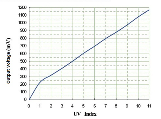
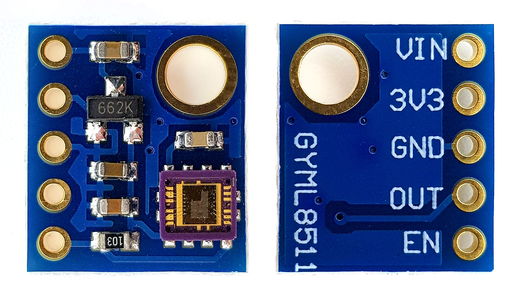
Guva-S12SD UV sensor No. 1: Adafruit
The Adafruit module is shown on the left in the picture above. It is helpful that the manufacturer has printed the most important information on the back:
- Power supply: 2 – 5 volts
- Wavelength range: 240 – 370 nm
- UV index ≈ output voltage / 0.1
int sensorPin = 0;
float analogSignal;
float voltage;
float uvIndex;

void setup(){
  Serial.begin(9600);
}

void loop(){
  analogSignal = analogRead(sensorPin);
  voltage = analogSignal/1023*5;
  uvIndex = voltage / 0.1;
  Serial.print("Signal: "); Serial.println(analogSignal);
  Serial.print("Volt: "); Serial.println(voltage);
  Serial.print("UV-Index: "); Serial.println(uvIndex);
  Serial.println("------------------------------");

  delay(1000);
}
For completeness, here is the wiring, even if it couldn’t be easier.

Guva-S12SD UV Sensor No. 2: no-name (purple)
The sensor module most commonly found in online stores is the purple one at the middle. Anyway, I absolutely can’t recommend it.
The module can handle 2.5 to 5 volts and, like the Adafruit module, has an output pin. However, I found that even on cloudy October day it already delivered the maximum value (i.e. output voltage = input voltage). I read somewhere else that you shouldn’t work with an angle of incidence of 90°. But there was no hint how to exactly do this instead. Or in other words, how can I expose the module to the sun always in the same way for reliable and reproducible results? To be fair, yes, the module measures UV radiation and it is quite sensitive. But for UV index determination, I think it is inappropriate.
Or am I doing something wrong? If you have had your own experiences, I would appreciate your feedback.
With this module, but also other UV sensors, you often come across the following table:

Apparently, this table is copied over and over again and seems to be applied without thinking. After some searching I found that it probably goes back to the UVM-30A sensor, which seems to have gone a bit out of fashion. A data sheet of a module based on this sensor can be found here. And there you will also find the relationship between UV index and output voltage, which is the basis for the table. You shouldn’t just apply it 1:1 to other modules.
Guva-S12SD UV Sensor No. 3: Waveshare
Now again to a more enjoyable device. According to the manufacturer, theWaveshare module can withstand 3 to 5.5 volts and delivers similar results to the Adafruit model. It is also worth noting that it has a small potentiometer for calibration. More information can be found here on the manufacturer’s pages.
ML8511
The ML8511 has its highest sensitivity in the range of 280 to 390 nm. It provides a voltage signal that increases linearly with the UV radiation intensity:
Vout [V] ≈ (UV-Intensity ⋅ 0,12) + 1 with UV-intensity in mW/cm2 at a diameter of 365 nm
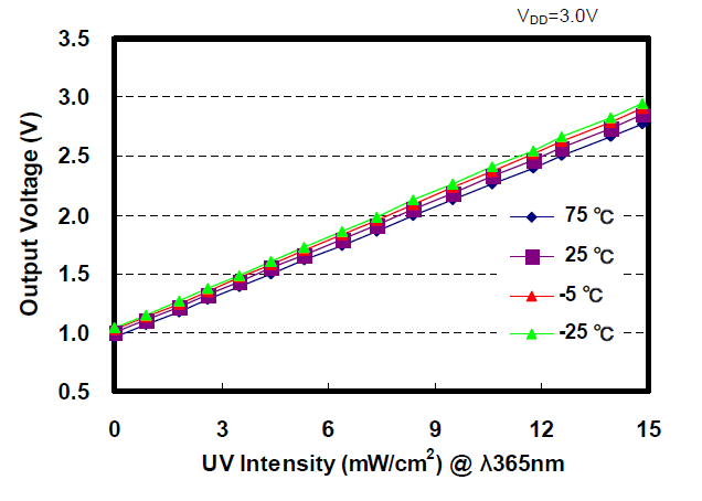
The sensor itself should be supplied with 2.7 – 3.3 volts, but many modules, such as the one shown above, can also tolerate 5 volts. 3.3 volts can then be tapped via the 3.3 volts pin. The Enable Pin is active high, i.e. when connected to GND, the module is switched off. A data sheet for the sensor can be found here.
Circuit and sketch I save myself in this case. Everyone should be able to handle this, right? If not, here is a good post on the Sparkfun web pages. But it’s worth reading anyway.
SI1145 (GY 1145)
Features of the S1145 sensor
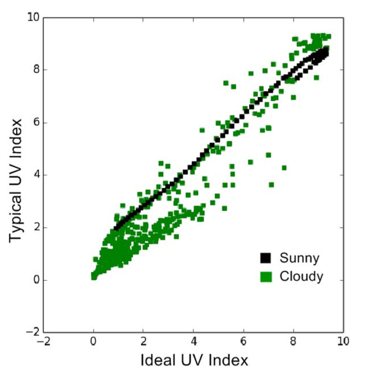
The SI1145 is a very amazing component that doesn’t actually have a UV sensor. Instead, it has sensors for the visible (ALS = ambient light) and the infrared light (IR). The UV index is calculated from the measured values of these sensors with a number of coefficients, which works surprisingly well, at least in sunny weather. The result of this calculation is provided as a 16-bit value and must then be divided again by 100. The UV index is therefore determined in a very high resolution. Of course, this does not mean that this UV index corresponds to reality to that degree. It is still an approximation that can deviate from the real value, especially in cloudy weather. Here is a graphic from the data sheet:
In addition, the SI1145 offers a connection for an infrared LED, with which it can be used as a proximity sensor (PS). According to the data sheet, 50 cm range is possible. The “bigger brothers” SI1146 and SI1147 even have 2 and 3 connectors for IR LEDs, respectively. An interrupt output can report – if configured appropriately – when readings are available for retrieval.
Features of the SI1145 modules
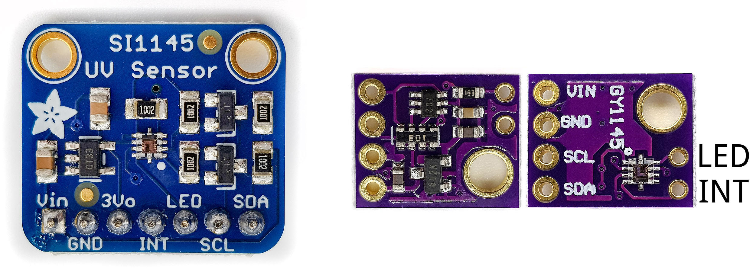
Unfortunately, I haven’t found a library that really takes full advantage of the SI1145 features. For the ones I have tested the ALS and IR functions were only partially implemented, and the same applies for PS function. Interrupt functions were missing as well.
However, this is a post about UV sensors. And the SI1145 modules do this task well with the Adafruit library.
Communication is via I2C (address 0x60). The power supply is 3 -5 V. The price range ranges from 5 euros to 22 euros. If you patient enough to wait for a few weeks, you will take the cheap ones from China. But you can also consider supporting Adafruit for their good work. Prices start at about 11 euros (as of Oct. 2019).
Measurements with the Adafruit SI1145 library
Adafruit provides its library Adafruit_SI1145_Library on Github. You can download it via the link or install it via the Arduino Library manager (search term: SI1145). The included sample sketch works wonderfully in terms of UV index measurement without further adjustments.
In addition, the SI1145 also provides ALS (ambient light) and IR values, which are not really helpful. But this is probably more due to the library than to the sensor. For example, the ALS value reacts little even to intense light. This is strange because the SI1145 uses these values for the determination of the UV index and that goes quite well. I also tried the PS measurement. It works, albeit with a fairly short range < (10 cm). There is certainly something that can be improved with the right settings. Maybe I’ll write a library myself soon (addendum: I’ve written a library now, look here).
But again, the topic here is the UV index determination. And that works pretty well.
I don’t want to or don’t have to write much more about it because at Adafruit there is already a good guide for the module and the library. You can find it here. I’m not a friend of copying things without providing added value.
VEML6075
As the last representative of UV sensors, I would like to introduce the VEML6075. Maybe you will come across his little brother, the VEML6070. The VEML6075 is preferable because it has two separate channels for UV-A and UV-B. This also distinguishes it from all other sensors presented here. A weighting of the UV-A and UV-B proportions makes the calculated UV indices much more reliable.
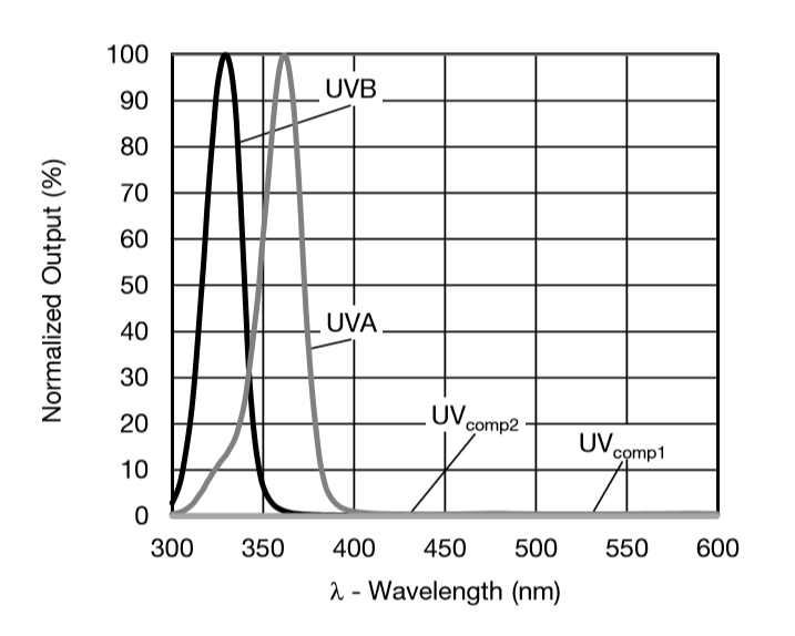
The photodiodes used – like other UV photodiodes – have a certain cross-influence by visible and infrared light. In the so-called Application Notes, which are available in addition to the data sheet, these factors are calculated using coefficients (UVcomp1 and UVcomp2). Not everyone will want to deal with it in detail. But a look at the application notes gives at least an impression of how complex the UV index determination actually is.
Since there is a very good library and instructions from Sparkfun, you don’t have to dig through the original documents unless you want to adjust the default values. Nevertheless – the VEML6075 is quite complex. If you want to use it, then you should deal a little with the details and not blindly believe the values of the first example sketch. Not that you have to say at some point: “According to the measured values, I shouldn’t have got sunburn!”.
VEML6075 Modules

VEML6075 modules are available from a number of different vendors, including Sparkfun and Adafruit, but also various no-name versions, such as the model shown above. Prices vary between 4 and 15 euros (as of Oct. 2019). Be careful with the power supply because some modules do not tolerate 5 volts. The above should also tolerate 5 volts, recognizable by the voltage regulator (662K) on the back.
Communication takes place via I2C. If the module does not tolerate 5 volts, then this also applies to the I2C cables. In this case, use voltage dividers or logic converters. The jumper at the top right of the back of the module is closed. I suspect that the I2C lines are connected to pull-up resistors as a result.
Wiring to the Arduino or other microcontrollers is very easy. In addition to the power supply, only SDA and SCL need to be connected. I do not provide a circuit accordingly.
Using the Sparkfun Library
You can install the Sparkfun library via the link above or via Arduino library manager. It is then best to go through the instructions and the included sample sketches. In these you will learn how to make different settings, such as the measurement time (integration time) or the resolution (normal dynamic vs. high dynamic). Since all this is very well documented, it is not worth writing my own instructions here.
By the way, don’t be surprised if you get some negative UV values or UV indices during measurements you do inside. Apparently, the correction factors are optimized for outside measurements. This does not mean that the other UV sensors presented here measure more “correctly”. It only shows once again that UV measurement is not entirely trivial and one should fundamentally question measured values.
UV sensors: a conclusion
There are a number of different UV sensors or sensor modules available. In the end, they all have photodiodes that detect the radiation intensity as a photo current, which is then evaluated as voltage. Guva-S12SD, UVM-30A and ML8511 provide an analog signal, while SI1145 and VEML6075 provide the data digitally via I2C.
The UV indices determined with the UV sensors or calculated from the signals are basically approximate values, since a correct determination would require the measurement and weighting of the intensities of the different wavelengths. The only sensor that goes in this direction to a certain extent is the VEML6075. In addition, it has correction factors to calculate the transverse influences from the visible and the infrared range. The SI1145 occupies a special position as it extrapolates UV indices from the data of the visible and infrared range. The data provided by the simple analog sensors must definitely be critically questioned. Some modules based on the Guva-S12SD are in my opinion completely unsuitable.
Acknowledgement
I owe the sunflower picture to Couleur on Pixabay. Unlike usual, I didn’t modify the post picture this time.
And then a thank you to the hardworking staff of Adafruit and Sparkfun for publishing the instructions and libraries.
Hallo Wolfgang,
Deine Auflistung könnte um diesen sehr interessanten UV A-B-C-Sensor bereichert werden: OSRAM AS7331
https://ams-osram.com/de/products/sensors/ambient-light-color-spectral-proximity-sensors/ams-as7331-spectral-uv-sensor
Das tolle an dem Chip ist seine 3-fach Sensor-Kombi, die auch etwas vom UV-C-Bereich erfasst. Aus Datenblatt:
UVA-Channel (λ = 315 nm – 410 nm)
UVB-Channel (λ = 280 nm – 315 nm)
UVC-Channel (λ = 240 nm – 280 nm)
SparkFun bietet ihn auf 2 Test-Boards mit Qwiic-Steckern:
https://www.sparkfun.com/products/23517
https://www.sparkfun.com/products/23518
Viele Grüsse
Hallo Harry,
vielen Dank für die Anregung. Ich habe hier auch noch zwei andere liegen. Die muss ich mir mal im Verbund schauen und mal ein kleines Update schreiben. Allerdings verspreche ich lieber nichts. Viele Ideen, wenig Zeit!
VG, Wolfgang
ltr390?? x2 price down of veml6070 on aliexpress.
VEML6075 too expensive now!( up to 30$ on ali. VEML6075 analogs ?
It’s really a shame that the VEML6075 has become that expensive. Its life cycle has ended, unfortunately. I have not yet tried the LTR390, but ordered one. Thanks for the hint!
just finded new analog even better for that price, only ic, no modules. and was not on the aliexpress, ebay.( only mouser and …
AS7331 ! new, Nov.2022 ic, 3 channels dva, dvb, dvc! i2c, etc…
*uva, uvb, uvc.
+1 founded analog for veml6075(2 channel uv) = SI1133. they are in aliexpress, 20$. but no any modules, only ic.
f** dont understand, why somebody posted that, just checked and SI1132, SI1133 = ambient and uv. may be this is what they means as “2 channel”.
so +-= ltr390?
Ambient Light Photo Sensor, I2C Output, 625nm Peak Sensitivity, 1.62V to 3.6V Supply, DFN-10
Thanks for all the information. These parts (AS7331 / SI1133) are so small that at least I am not able to solder them. But I will have a look at the LTR390.
I am just underway to compare some UV-Sensors myself.
My special interest is to evaluate the difference of S12SD (UVB+A) and VEML6070 (UVA) sensors
in order to obtain the dominant contribution of the UV-B signal, which is relevant for skin exposition time.
I am using S12SD sensors from Adafruit and the ‘purple’ variant.
The gain factors provided by @Heusinkveld were already a great help to bring the two S12SD sensors
to a comparable signal level.
Just by accident I came across a very helpful descriptiom of the ‘purple’ variant’s properties:
https://protosupplies.com/product/guva-s12sd-uv-light-sensor-module/
This sensor seems in fact to be optimized for low UV intensity but can be adapted to measurements in sunlight.
Interesting overview. I think I have some new insights to complement your article.
I reverse engineered the purple pcb that includes a dual amplifier for the GUVA S12 SD sensor and I did the same for the Adafruit version (with single amplifier). The results:
-Purple pcb: amplification 262.3 million (and operational amplifier LM358 with 5 nA input offset current)
-Adafruit: amplification 4.3 million
-Reference design as proposed by the sensor manufacturer of GUVA S12 SD: amplification 6.8 million (suggested <1 nA input offset current)
So it is no surprise that the purple circuit does not work outdoors and the amplifier itself is also not recommended!
I also discovered that the VEML6075 is an end of life product (discontinued). There is no replacement yet.
Very useful information! Now I understand the issue with the purple module. Great thanks!