About this Post
In the last post, I showed you how to upload sketches to STM32 boards using the Arduino IDE. In this post, I would now like to go one step further and present some selected functions. On the one hand, this includes basic features that are not standard in the Arduino range of functions but are often required, such as timers, PWM or various energy-saving modes. On the other hand, I will go into the peculiarities of the STM32 implementation for well-known functions such as I²C, SPI or interrupts. And finally, there are certain extras that not every Arduino board offers, such as the digital-to-analog converter (DAC) or the real-time clock (RTC).
Here is an overview of the topics:
- Board selection for this article
- Hardware timer interrupts
- Pulse Width Modulation (PWM)
- Analog-to-digital converter (ADC)
- Digital-to-analog converter (DAC)
- External interrupts
- I²C
- SPI
- HardwareSerial
- SoftwareSerial
- Independent Watchdog (IWDG)
- Real Time Clock (RTC)
- Low-power modes
- Appendix – Extended RTC sketch
Programming levels of the SM32 boards
Microcontrollers (MCUs) can be programmed at different levels of abstraction. In the case of STM32 MCUs, these are essentially
- Register level (“Bare-Metal”, “Low-Level”): You access the registers directly via structures and bit masks. This is very efficient, but the least portable.
- CMSIS (Cortex Microcontroller Software Interface Standard): Is specified by ARM and is supplied with ST. IRQ names and core functions, for example, are defined there.
- ST-own abstractions:
- LL (Low-Layer): Still close to the registers.
- HAL (Hardware Abstraction Layer): Higher abstraction, higher portability, but more overhead.
- Frameworks / cores for high-level development: This includes in particular the Arduino core board package from STM32duino, which I already used in the last article. HAL and LL are the basis for this but are “hidden” behind the Arduino-typical functions.
This article is only about the high-level programming. However, as you will certainly come across terms such as HAL, LL or bare metal when dealing with the STM32 boards, I didn’t want to leave them unmentioned.
Board selection for this article
Of course, I cannot discuss all STM32 boards here. Therefore, I have made the same selection as in the first part of the article:
- The “BluePill” based on the STM32F103C8
- The “BlackPill” based on the STM32F411
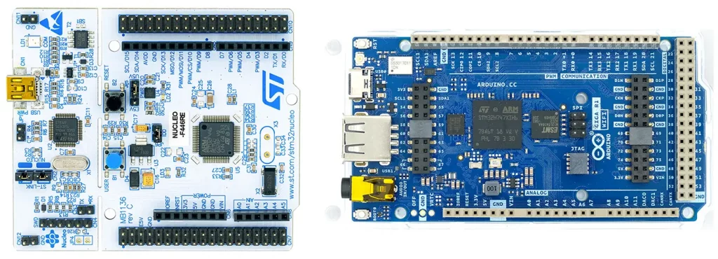
- The Nucleo-L432KC board, as a representative of a Nucleo-32 board
- The Nucleo-F446RE board, as a representative of a Nucleo-64 board
- The Arduino GIGA R1 WIFI, as an example of an STM32-based Arduino board
The main focus is on the first three boards.
And one more note in advance: When I refer to”the Blackpill” or”the BluePill” in this article, I am referring to the above-mentioned types. There are also different versions or fakes of these types. Therefore, your boards may behave differently in certain aspects than discussed here.
Pinout of the boards discussed here
“BluePill” (STM32F103C8)
I took the pinout diagram for the BluePill shown below from this nice article by Renzo Mischianti. If you want to dive deeper into the specific features of the BluePill boards, I can highly recommend Renzo Mischianti’s articles.
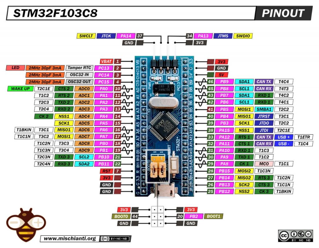
Peculiarities of this BluePill board:
- Some pins are 5-volt tolerant (green squares); others only tolerate 3.3 volts (red-brown squares).
- The following applies to PC13, PC14, and PC15:
- These pins must not supply any current in the HIGH state, i.e., you can use the “HIGH” state as a logic output, but not operate an LED with it, for example.
- In the LOW state, the pins may tolerate a maximum of 3 mA (the LED on PC13 is connected to 3.3 volts and lights up when PC13 is OUTPUT/LOW).
- They shall not work at a frequency higher than 2 MHz and shall not be loaded with more than 30 pF.
- The board can be operated via the 3.3-volt or 5-volt pins. VBAT only supplies power to the RTC and backup registers.
“BlackPill” STM32F411
As with the BluePill, I also used Renzo Mischianti’s pinout for the BlackPill. If you want to delve even deeper into the details of the BlackPill boards, I recommend Renzo’s series of articles. This article is a good starting point.
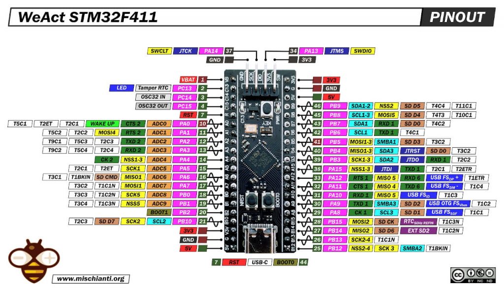
Peculiarities of this BlackPill board: The same restrictions and notes for the pins apply as for the BluePill board, but considerably more pins are 5-volt-tolerant.
Pinout Nucleo-L432KC
The Nucleo-L432LC board attempts to achieve a certain compatibility with the Arduino Nano boards. The pinout largely matches the pin designations and functionalities.
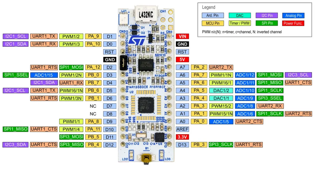
Peculiarities of the Nucleo-L432KC:
- The GPIOs are only compatible with 3.3 volts.
- Pins D7 and D8 are not connected to anything. I will come back to this in the solder bridges section below.
- You can use the “3.3V” and “5V” pins to supply other components with power. The maximum permissible current depends on the type of power supply of the board. See the UM1956 user manual.
- To supply the board via the 3.3V and 5V pins, you must change the configuration of the solder bridges SBxy (see below).
- You can supply the board with 7 to 12 volts via VIN.
Pinout Nucleo-F446RE and Arduino GIGA R1 WIFI
You can find a pinout diagram of the Nucleo-F446RE here. A total of 50 GPIOs are available with this board. You can find a pinout diagram of the Arduino GIGA R1 WIFI here on the Arduino pages. This board even has a whopping 76 GPIOs.
Solder bridges of the Nucleo boards
If you look at the Nucleo-L432KC board (or other Nucleo boards), you will see many solder bridges labeled “SBxy“. Some of them are open, the others are closed via 0 Ω resistors. A detailed description of the solder bridges of the Nucleo-32 boards can be found in UM1956 mentioned above. Here are some selected settings:
- To supply the board with power via the 3.3-volt pin, SB9 and SB14 must be open. As a restriction, the board-internal ST-LINK is then not available.
- To supply the board via the 5-volt pin, SB9 must be open. The board-internal ST-LINK is then not available. The supply via the 5-volt pin and debugging via ST-LINK can be combined, but then a certain procedure must be followed (see UM1956 again).
- If you want to use pins D7 and D8 as GPIOs (PC14/PC15), then SB4, SB5, SB7 and SB17 must be open; SB6 and SB8 must be closed. However, you will then no longer be able to use the external crystal for the RTC.
As you can see, it’s quite complex. And before you start soldering your board, be sure to read the UM1956 User Manual carefully!
The Nucleo-F446RE board also has even more solder bridges. Accordingly, there are also peculiarities here, such as the open solder bridges (SB48 / SB49) on PC14 and PC15. Explanations can be found in the UM2324 user manual.
Hardware timer interrupts
But now we finally start with the practical part. First, let’s take a look at how to program timer overflow interrupts using the HardwareTimer class. The definition of the class can be found in HardwareTimer.h. This file is located in the directory …\Arduino15\packages\STMicroelectronics\hardware\stm32\2.11.0\libraries\SrcWrapper\inc. The corresponding file HardwareTimer.cpp is located “nearby”, under …\SrcWrapper\src. If you want to delve deeper into the topic and get to know all the functions of the HardwareTimer class, it is worth taking a look at these files.
The STM32 MCUs have several timers (TIMx). You can easily find out what these are in the data sheet of the underlying microcontroller. It also states whether they are 16-bit or 32-bit timers.
I prefer to use the TIM2 timer for the examples, as it is available on all the boards under consideration. On the BluePill TIM2 is a 16-bit timer; on the BlackPill and the Nucleo-L432KC it is a 32-bit timer.
One interrupt
Control via the prescale factor and overflow value
Let’s take a look at the first example:
HardwareTimer myTim(TIM2);

void setup() {
    uint32_t prescaleFactor = 10000;    // fits well to the BlackPill
    //  uint32_t prescaleFactor = 7200; // fits well to the BluePill
    //  uint32_t prescaleFactor = 8000; // fits well to the L432KC
    //  uint32_t prescaleFactor = 8400; // fits well to the F446RE
    uint32_t timerOverflow = 10000;
    Serial.begin(115200);
    myTim.setPrescaleFactor(prescaleFactor);
    myTim.setOverflow(timerOverflow);
    myTim.attachInterrupt(onTimer);
    myTim.resume();
}

void loop() {}

void onTimer() {
    Serial.println("1 second");
}
You will receive the message “1 second” on the serial monitor every second.
Explanations to the sketch
Use HardwareTimer myTim(TIM2) to create the myTim object and assign TIM2 to it. Define the prescaler factor with setPrescaleFactor(). It can have a value between 1 and216. The count frequency of the timer is the system clock divided by the prescaler factor. You should select it so that you can calculate comfortably with it. The examples in the sketch regulate the counting frequency down to 10 kHz. You set the overflow with setOverflow(). For 16-bit timers, the maximum value is216, for 32-bit timers it is a maximum of232-1, as timerOverflow is passed as a 32-bit number.
In the example above, overflow is 10000, and therefore the overflow frequency is 1 Hz according to the following formula:
![\[ F_{\text{overflow}} = \frac{\text{systemClock}}{\text{prescaleFactor}\cdot \text{timerOverflow}} \]](https://wolles-elektronikkiste.de/wp-content/ql-cache/quicklatex.com-5ff83c5a4c1153c3b7803f077508e4d2_l3.png "Rendered by QuickLaTeX.com")
Accordingly, the minimum interrupt frequency when using a 16-timer on a BlackPill board is 100 [MHz] / (216 *216) = ~0.023 [Hz]. For a 32-bit timer, it would be ~3.55*10-7 [Hz], which corresponds to a period of approx. 32.5 days.
You pass the interrupt service routine (ISR) to be executed to the function attachInterrupt. Use resume() to start or continue the counter.
Control via the period
Alternatively, you can simply set the period. Then you don’t have to calculate and can port the sketch unchanged to other boards:
HardwareTimer myTim(TIM2);

void setup() {
    uint32_t timerOverflow = 1000000;
    Serial.begin(115200);
    myTim.setOverflow(timerOverflow, MICROSEC_FORMAT);
    myTim.attachInterrupt(onTimer);
    myTim.resume();
}

void loop() {}

void onTimer() {
    Serial.println("1 second");
}
I think the sketch is self-explanatory.
Control via the frequency
You can also set the overflow frequency as a further option. However, 1 Hz is the slowest setting you can make.
HardwareTimer myTim(TIM2);

void setup() {
    uint32_t timerOverflow = 1; // 1 Hz is the slowest frequency
    Serial.begin(115200);
    myTim.setOverflow(timerOverflow, HERTZ_FORMAT);
    myTim.attachInterrupt(onTimer);
    myTim.resume();
}

void loop() {}

void onTimer() {
    Serial.println("1 second");
}
Multiple interrupts
You can, of course, also set up several interrupts. Here is an example that uses arrays for the timer objects and ISRs. LEDs are “toggled” in the ISRs. If you want to try out the sketch, connect LEDs to the corresponding pins.
HardwareTimer myTim0(TIM1);
HardwareTimer myTim1(TIM2);
HardwareTimer myTim2(TIM3); // TIM15 for L432KC; TIM13 for F446RE
HardwareTimer myTim3(TIM4); // TIM16 for L432KC; TIM14 for F446RE
HardwareTimer* myTimers[4] = {&myTim0, &myTim1, &myTim2, &myTim3};

const int ledPin[4] = {PA0, PA1, PA2, PA3}; // A0, A1, A2, A3: for L432KC

uint32_t timerOverflow[4] = {500000, 1200000, 1700000, 2200000};

void onTimer0() {
    digitalWrite(ledPin[0], !digitalRead(ledPin[0]));
}

void onTimer1() {
    digitalWrite(ledPin[1], !digitalRead(ledPin[1]));
}

void onTimer2() {
    digitalWrite(ledPin[2], !digitalRead(ledPin[2]));
}

void onTimer3() {
    digitalWrite(ledPin[3], !digitalRead(ledPin[3]));
}


void (*onTimer[4])(void) = {onTimer0, onTimer1, onTimer2, onTimer3};

void setup () {
    for (int i=0; i<4; i++){
        pinMode(ledPin[i], OUTPUT);
        myTimers[i]->setOverflow(timerOverflow[i], MICROSEC_FORMAT);
        myTimers[i]->attachInterrupt(onTimer[i]);
        myTimers[i]->resume();
    }
}

void loop() {}
Timer interrupts for the Arduino GIGA R1 WIFI Board
Since the HardwareTimer class is firmly anchored in the STM32 Arduino Core package, it does not work with the Arduino GIGA R1 WIFI board if you use the standard Arduino board package.
Alternatively, you can use the Portenta_H7_TimerInterrupt library, which you can install via the Arduino library manager. It was written for the Portenta H7 board, but also works with the Arduino GIGA R1 WIFI, as both have the same microcontroller.
When compiling the example sketches you will get the error message: “This code is intended to run on the MBED ARDUINO_PORTENTA_H7 platform! Please check your Tools->Board setting” . The compiler also tells you which file produced this error. It is Portenta_H7_ISR_Timer.hpp on the one hand and Portenta_H7_TimerInterrupt.h on the other.
Go to the files and search for the line (probably 30):
#if ( ( defined(ARDUINO_PORTENTA_H7_M7) || defined(ARDUINO_PORTENTA_H7_M4) ) && defined(ARDUINO_ARCH_MBED) )
Change it to:
#if ( ( defined(ARDUINO_PORTENTA_H7_M7) || defined(ARDUINO_PORTENTA_H7_M4) || defined(ARDUINO_GIGA) ) && defined(ARDUINO_ARCH_MBED) )
You can proceed similarly in the example sketches or you can comment out the relevant lines. Then it should work.
Pulse Width Modulation (PWM)
Pulse width modulation (PWM) can also be easily implemented using the hardware timer class. Here is a simple example:
HardwareTimer Timer(TIM1);

void setup() {
    uint32_t channel = 3;
    int pwmPin = PA10; // D0 for L432KC; D2 for F446RE
    uint32_t frequency = 1;
    uint32_t dutyCycle = 20; // 20%
    Timer.setPWM(channel, pwmPin, frequency, dutyCycle);
}

void loop() {}
The outputs for the various timers and channels are assigned to specific pins. For the boards discussed here, you will find the assignment in the pinout diagrams. Otherwise, take a look at the corresponding data sheet. If you upload the above program and connect an LED to the PWM pin, you will see how it lights up every second for 200 ms.
You would expect to automatically receive an inverted output at the T1C3N output (e.g., PB1 on the BlackPill). But this is not the case.
You can call callback functions at the end of the period and/or the DutyCyle to initiate further actions. Here is a small example:
HardwareTimer Timer(TIM1);

void setup() {
    uint32_t channel = 3;
    int pwmPin = PA10; // PA10 = D0 on the L432KC and D2 on the F446RE
    uint32_t frequency = 1;
    uint32_t dutyCycle = 20; // 20 %

    Serial.begin(115200);
    Timer.setPWM(channel, pwmPin, frequency, dutyCycle, periodCompleted, compareMatch);
}

void loop() {}

void periodCompleted(){
    Serial.print("Hi");
}

void compareMatch(){
    Serial.println("Ho");
}
You have a little more options with this variant:
HardwareTimer Timer(TIM1);

void setup() {
    //  uint32_t compareValue = 2000;
    Timer.setPrescaleFactor(10000); // -> 10 KHz für BlackPill (STMF411); adjust to your board
    Timer.setOverflow(10000); // -> 1 Hz
    Timer.setMode(3, TIMER_OUTPUT_COMPARE_PWM1, PA10); // channel, mode, pwmPin
    Timer.setCaptureCompare(3, 20, PERCENT_COMPARE_FORMAT); // channel, duty cycle (%), format
    //  Timer.setCaptureCompare(3, compareValue); // channel, compareValue
    Timer.resume();
}

void loop() {}
TIMER_OUTPUT_COMPARE_PWM1 is one of the possible timer modes. These modes are defined as enum (TimerModes_t) in HardwareTimer.h. Look there if you want to try the other modes.
PERCENT_COMPARE_FORMAT is one of the possible compare formats. These are defined in the enum TimerCompareFormat_t in HardwareTimer.h. If you do not pass a format to setCaptureCompare(), then TICK_COMPARE_FORMAT is used as the default. In this case, you pass the compare value as an absolute counter value.
PWM with the Arduino GIGA R1 WIFI
For PWM on the Arduino GIGA R1 WIFI, you can use the Portenta_H7_PWM and Portenta_H7_Slow_PWM libraries. However, as described above for the Portenta_H7_TimerInterrupt library, you must also add the board definition for the Arduino GIGA R1 WIFI.
Analog-to-digital converter (ADC)
Next, let’s take a look at the ADC of the STM32 boards. Please note the following regarding the reference voltage:
- The maximum resolution is 12 bits. The BluePill and BlackPill boards do not have a VREF pin. VDD is the standard reference.
- Although there is a VREF pin on the Nucleo-L432KC, you can only tap the reference voltage there, but not apply it.
- An external reference can be used with the Nucleo-F446RE if the solder bridges are set accordingly.
For programming you can use the usual Arduino functions. For the Arduino GIGA R1 WIFI board there is the Arduino_AdvanceAnalog library, which supports the use of its three ADCs.
Testing the accuracy of the ADC
I applied voltages between 0 and 3.3 volts, converted them with analogRead() and checked the result with my multimeter. I know from my multimeter that it is very precise. I averaged 50 readings at a time, which reduced the noise to a few millivolts.
Here is the sketch:
const float vRef = 3.3;

void setup() {
    Serial.begin(115200);
    analogReadResolution(12);
}

void loop() {
    unsigned long int rawVal = 0;
    float voltage = 0.0;
    for (int i=0; i<50; i++) {
        rawVal += analogRead(PA1);
        delay(1);
    }
    voltage = (rawVal * vRef) / (4095 * 50);
    Serial.print("Raw: ");
    Serial.print(rawVal);
    Serial.print("\tVoltage [V]: ");
    Serial.println(voltage, 3);
    delay(1000);
}
And here is a typical output:
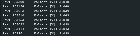
And here are the results over the entire voltage range of the BlackPill board:
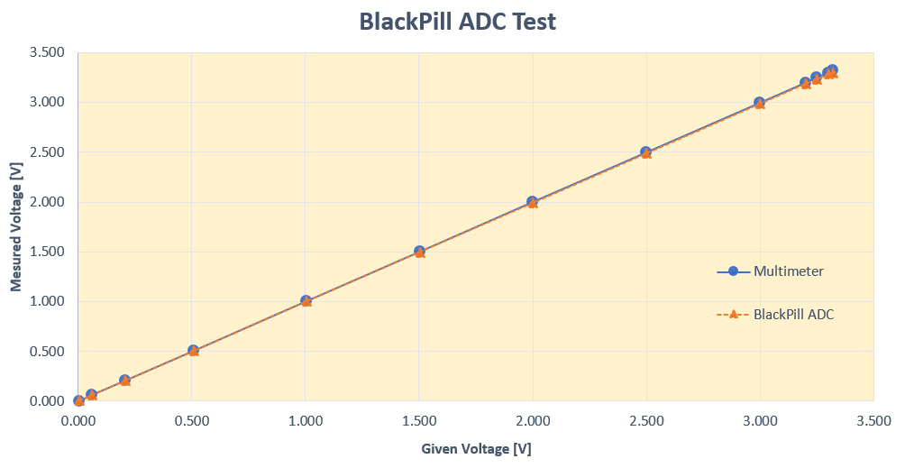
The result looks pretty good. The linearity is perfect. If you look closely, you can see that the slope of the ADC line is a little bit lower than that of the multimeter line. The reason was the operating voltage of the BlackPill board, which was not 3.3 volts but 3.311 volts. After adjusting vref in the sketch above, the lines were even better aligned.
Similarly good results were achieved with the BluePill board (STM32F103C8) and the Nucleo-L432KC.
Digital-to-analog converter DAC
Normally, when using analogWrite(), you generate a PWM signal. However, if you apply analogWrite() to a DAC pin, you will automatically receive a real analog signal. DAC outputs can be found on the Nucleo boards and the Arduino GIGA R1 WIFI, but not on BluePill and BlackPill.
Use the following sketch to enter raw DAC values and output the calculated voltages:
void setup() {
    Serial.begin(115200);
    analogWriteResolution(12); // 12 bit resolution
}

void loop() {
    float vref = 3.3;
    if(Serial.available()){
        int rawVoltage = Serial.parseInt();
        analogWrite(A3, rawVoltage);
        Serial.print(rawVoltage);
        Serial.print(" -> ");
        float voltage = (vref * rawVoltage / 4095.0);
        Serial.print(voltage, 3);
        Serial.println(" [V] (calc.)");
    }
}
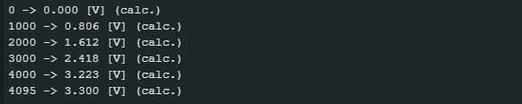
I used the sketch to compare the calculated voltage with the actual voltage. Here is the result:

Over a wide range, the actual values match the calculated values perfectly. Only at the ends does the curve bend away from the actual values. I was unable to generate voltages lower than 0.045 volts (analogWrite(0)) or higher than 3.28 volts (analogWrite(4095)). Apart from that, I was very satisfied with the result. If you want to be even more precise, measure the actual board voltage at (V)REF and correct vref in the sketch above accordingly.
I was able to generate voltages between 0.02 volts and 3.226 volts on the Arduino GIGA R1 WIFI. However, the board voltage here was only 3.262 volts.
External interrupts
You can set up external interrupts (EXTI) on almost all GPIOs. You should only avoid PB2 (on the BlackPill), PC13, PC14, and PC15.
However, there is one more restriction. You have 16 EXTI lines (0-15) at your disposal. However, the EXTI lines can only be assigned to pins whose number corresponds to the EXTI line. So EXTI0 → PA0, PB0; EXTI1 → PA1, PB1; etc. And you can only assign one interrupt per line. Consequence: You can set up interrupts on PA0 and PB1 in parallel, but not on PA0 and PB0.
I tried setting up four external interrupts with a BlackPill board. Each of the four pins is connected to GND via a pushbutton.
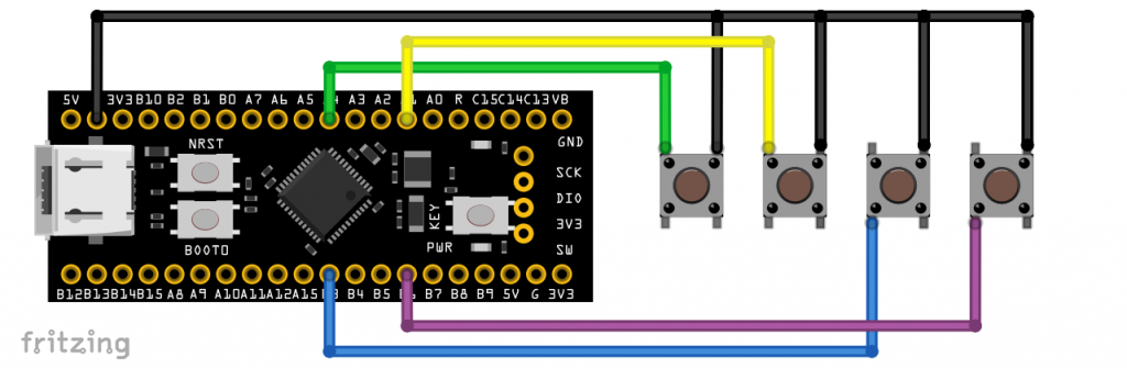
The pins are set to INPUT_PULLUP mode. The associated interrupts are triggered on the falling edge, i.e. when the buttons are pressed. The triggering pin is displayed on the serial monitor. Here is the sketch:
/* tested on a BlackPill (F411CE) */
int intPin[4] = {PA4, PA1, PB3, PB6};
volatile bool keyPressed = false;
volatile int intKey = 0;

void onKey0 () {
    keyPressed = true;
    intKey = 0;
}

void onKey1 () {
    keyPressed = true;
    intKey = 1;
}

void onKey2 () {
    keyPressed = true;
    intKey = 2;
}

void onKey3 () {
    keyPressed = true;
    intKey = 3;
}

void (*onKey[4])(void) = {onKey0, onKey1, onKey2, onKey3};

void setup() {
    Serial.begin(115200);
    for (int i=0; i<4; i++) {
        pinMode(intPin[i], INPUT_PULLUP);
        attachInterrupt (digitalPinToInterrupt(intPin[i]), onKey[i], FALLING);
        delay(10);
    }
}

void loop() {
    if (keyPressed) {
        Serial.print("Key ");
        Serial.print(intKey);
        Serial.println(" has been pressed");
        delay(500);
        intKey = 0;
        keyPressed = false;
    }
}
I2C
You can use two I²C interfaces on the BluePill (STM32F103C8). On the BlackPill (STM32F411), the Nucleo-L432KC, the Nucleo-F446RE and the Arduino GIGA R1 WIFI there are three interfaces. If you only use one interface and do not define anything else, then SDA and SCL are located on the following pins:
- BluePill / BlackPill: SDA – PB7 / SCL – PB6
- Nucleo-L432KC: SDA – PB_7 (D4) / SCL – PB_6 (D5)
- Nucleo-F446RE: SDA – PB_9 (D14) / SCL – PB_8 (D15)
- Arduino GIGA R1 WIFI: SDA – PB11 (D20) / SCL – PH4 (D21)
Illustrative example: MPU6000/MPU6050/MPU6500/MPU9250
I would like to explain the use of I2C on the STM32 boards using practical examples. I have selected the MPU6000, MPU6050, MPU6500 and MPU9250 acceleration sensors for this purpose. The sketches presented here work for all four sensors. I refer to them collectively as “MPUXXXX”.
This is not intended to be an article about these sensors, but a brief explanation is certainly necessary so that we can concentrate on the relevant I2C functions straight away.
- The MPUXXXX are woken up by an entry in their Power Management Register 1 (MPUXXXX_PWR_MGMT_1) and then continuously measure the acceleration of its x, y and z axes.
- The acceleration values are 16-bit numbers that are read “in one go” from 6 registers, starting with the MPUXXXX_ACCEL_XOUT_H register (MSB of the acceleration in the x direction).
- The 6 bytes are then converted into the three acceleration values accX, accY and accZ.
- In the examples, the resolution is +/- 2 g, i.e. 214 (= 16384) corresponds to one g.
Connection
Here you can see two MPU6500/MPU920 connected to I2C-1 (default) and I2C-2 of a BlackPillboard:
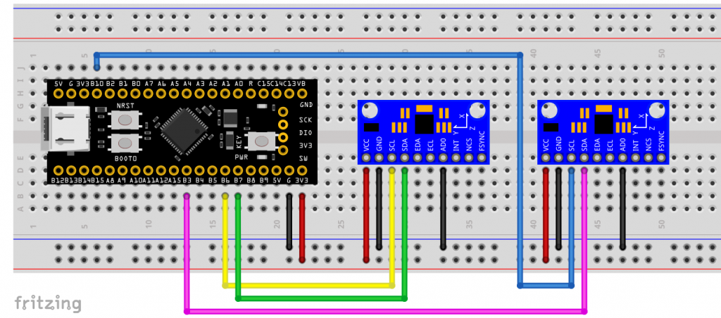
One I²C device attched to the standard pins
If you use the standard interface with the standard pins, there are no surprises regarding the I2C functions:
#include "Wire.h"
#define MPUXXXX_ADDR 0x68 // Alternatively set AD0 to HIGH  --> Address = 0x69
// MPUXXXX registers
#define MPUXXXX_PWR_MGMT_1 0x6B
#define MPUXXXX_ACCEL_XOUT_H 0x3B

char result[7]; // for formatted output

void setup() {
    Serial.begin(115200);
    Wire.begin();
    writeRegister(MPUXXXX_PWR_MGMT_1, 0x00); // wake up MPUXXXX
}

void loop() {
    uint8_t data[6];
    int16_t accX, accY, accZ;

    readRegister(MPUXXXX_ACCEL_XOUT_H, data, 6);

    accX = data[0] << 8 | data[1];
    accY = data[2] << 8 | data[3];
    accZ = data[4] << 8 | data[5];

    Serial.print("AcX = "); Serial.print(toStr(accX));
    Serial.print(" | AcY = "); Serial.print(toStr(accY));
    Serial.print(" | AcZ = "); Serial.println(toStr(accZ));

    delay(1000);
}

void writeRegister(uint8_t reg, uint8_t data) {
    Wire.beginTransmission(MPUXXXX_ADDR);
    Wire.write(reg);
    Wire.write(data);
    Wire.endTransmission(true);
}

void readRegister(uint8_t reg, uint8_t* buffer, uint8_t length) {
    Wire.beginTransmission(MPUXXXX_ADDR);
    Wire.write(reg);
    Wire.endTransmission(false);
    Wire.requestFrom((uint8_t)MPUXXXX_ADDR, length);
    for (int i=0; i<length; i++){
        buffer[i] = Wire.read();
    }
}

char* toStr(int16_t character) {
  sprintf(result, "%6d", character);
  return result;
}
For the sake of completeness, here is a sample output:

One I²C device attached to alternative pins
If you want to use alternative I²C pins, you must create a TwoWire object and pass the pins to it. It does not matter whether these are alternative pins of the I2C standardinterface or alternative interfaces.
#include "Wire.h"
#define MPUXXXX_ADDR 0x68 // Alternatively set AD0 to HIGH  --> Address = 0x69
// MPUXXXX registers
#define MPUXXXX_PWR_MGMT_1 0x6B
#define MPUXXXX_ACCEL_XOUT_H 0x3B

char result[7]; // for formatted output

/* create a TwoWire object */
TwoWire myWire(PB9, PB8); // SDA, SCL

void setup() {
    Serial.begin(115200);
    myWire.begin();
    writeRegister(MPUXXXX_PWR_MGMT_1, 0x00); // wake up MPUXXXX
}

void loop() {
    uint8_t data[6];
    int16_t accX, accY, accZ;

    readRegister(MPUXXXX_ACCEL_XOUT_H, data, 6);

    accX = data[0] << 8 | data[1];
    accY = data[2] << 8 | data[3];
    accZ = data[4] << 8 | data[5];

    Serial.print("AcX = "); Serial.print(toStr(accX));
    Serial.print(" | AcY = "); Serial.print(toStr(accY));
    Serial.print(" | AcZ = "); Serial.println(toStr(accZ));

    delay(1000);
}

void writeRegister(uint8_t reg, uint8_t data) {
    myWire.beginTransmission(MPUXXXX_ADDR);
    myWire.write(reg);
    myWire.write(data);
    myWire.endTransmission(true);
}

void readRegister(uint8_t reg, uint8_t* buffer, uint8_t length) {
    myWire.beginTransmission(MPUXXXX_ADDR);
    myWire.write(reg);
    myWire.endTransmission(false);
    myWire.requestFrom((uint8_t)MPUXXXX_ADDR, length);
    for (int i=0; i<length; i++){
        buffer[i] = myWire.read();
    }
}

char* toStr(int16_t character) {
  sprintf(result, "%6d", character);
  return result;
}
Using multiple I²C interfaces
If you want to use several I2C interfaces, you must create TwoWire objects for each one. If you define functions that use the TwoWire objects (such as writeRegister() and readRegister()), then you pass the TwoWire objects as a pointer or as a reference.
#include "Wire.h"
#define MPUXXXX_ADDR 0x68 // Alternatively set AD0 to HIGH  --> Address = 0x69
// MPUXXXX registers
#define MPUXXXX_PWR_MGMT_1 0x6B
#define MPUXXXX_ACCEL_XOUT_H 0x3B

char result[7]; // for formatted output

/* create two TwoWire instances */
TwoWire Wire_1(PB7, PB6); // you could also use the default Wire object instead
TwoWire Wire_2(PB3, PB10);

void setup() {
    Serial.begin(115200);
    Wire_1.begin();
    Wire_2.begin();
    writeRegister(&Wire_1, MPUXXXX_PWR_MGMT_1, 0x00); // wake up MPUXXXX-1
    writeRegister(&Wire_2, MPUXXXX_PWR_MGMT_1, 0x00); // wake up MPUXXXX-2
}

void loop() {
    uint8_t data[6];
    int16_t accX_1, accY_1, accZ_1, accX_2, accY_2, accZ_2;

    readRegister(&Wire_1, MPUXXXX_ACCEL_XOUT_H, data, 6);

    accX_1 = (data[0] << 8) | data[1];
    accY_1 = (data[2] << 8) | data[3];
    accZ_1 = (data[4] << 8) | data[5];

    Serial.print("AcX_1 = "); Serial.print(toStr(accX_1));
    Serial.print(" | AcY_1 = "); Serial.print(toStr(accY_1));
    Serial.print(" | AcZ_1 = "); Serial.println(toStr(accZ_1));
    Serial.flush();

    readRegister(&Wire_2, MPUXXXX_ACCEL_XOUT_H, data, 6);

    accX_2 = (data[0] << 8) | data[1];
    accY_2 = (data[2] << 8) | data[3];
    accZ_2 = (data[4] << 8) | data[5];

    Serial.print("AcX_2 = "); Serial.print(toStr(accX_2));
    Serial.print(" | AcY_2 = "); Serial.print(toStr(accY_2));
    Serial.print(" | AcZ_2 = "); Serial.println(toStr(accZ_2));
    Serial.println();

    delay(1000);
}

void writeRegister(TwoWire *_wire, uint8_t reg, uint8_t data) {
    _wire->beginTransmission(MPUXXXX_ADDR);
    _wire->write(reg);
    _wire->write(data);
    _wire->endTransmission(true);
}

void readRegister(TwoWire *_wire, uint8_t reg, uint8_t* buffer, uint8_t length) {
    _wire->beginTransmission(MPUXXXX_ADDR);
    _wire->write(reg);
    _wire->endTransmission(false);
    _wire->requestFrom((uint8_t)MPUXXXX_ADDR, length);
    for (int i=0; i<length; i++){
        buffer[i] = _wire->read();
    }
}

char* toStr(int16_t character) {
  sprintf(result, "%6d", character);
  return result;
}
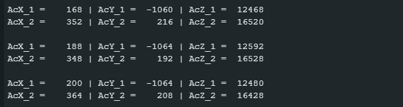
Here is the corresponding output:
Using libraries
Often, you will use ready-made libraries to control your I²C devices, such as my MPU9250_WE library. Most libraries for I2C devices allow you to pass TwoWire objects. This would then look something like this:
TwoWire Wire_1(PB7, PB6);
TwoWire Wire_2(PB3, PB10);
MPU9250_WE myMPU9250_1 = MPU9250_WE(&Wire_1);
MPU9250_WE myMPU9250_2 = MPU9250_WE(&Wire_2);
SPI
Everything is similar for SPI. Two SPI interfaces are available on the BluePill board (STM32F103C8), the Nucleo-L432KC and the Arduino GIGA R1 WIFI. There are four on the BlackPill (STM32F411) and the Nucleo-F446RE. The standard pins are:
- BluePill / BlackPill: SCLK – PA5 / MISO – PA6 / MOSI – PA7
- Nucleo-L432KC: SCLK – PB_3 (D13) / MISO – PB_4 (D12) / MOSI – PB_5 (D11)
- Nucleo-F446RE: SCLK – PA_5 (D13) / MISO – PA_6 (D12) / MOSI – PA_7 (D11)
- Arduino GIGA R1 WIFI: SCLK – PH6 (D13) / MISO – PJ11 (D12) / MOSI – PJ10 (D11)
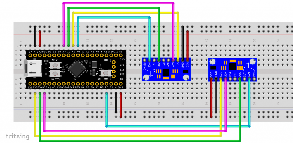
Here are two MPU6500/MPU9250 on SPI1 (default) and SPI2 of a BlackPill board:
One SPI device on the standard pins
The sketch for using the standard pins contains no surprises:
#include <SPI.h>
// MPUXXXX registers
#define MPUXXXX_PWR_MGMT_1 0x6B
#define MPUXXXX_ACCEL_XOUT_H 0x3B

char result[7]; // for formatted output
const int CS_PIN = PA4;  // Chip Select


void setup() {
    Serial.begin(115200);

    pinMode(CS_PIN, OUTPUT);
    digitalWrite(CS_PIN, HIGH);
    SPI.begin();

    writeRegister(MPUXXXX_PWR_MGMT_1, 0x00); // wake up MPUXXXX
}

void loop() {
    uint8_t data[6];
    int16_t accX, accY, accZ;
    readRegisters(MPUXXXX_ACCEL_XOUT_H, data, 6);

    accX = (data[0] << 8) | data[1];
    accY = (data[2] << 8) | data[3];
    accZ = (data[4] << 8) | data[5];

    Serial.print("AcX = "); Serial.print(toStr(accX));
    Serial.print(" | AcY = "); Serial.print(toStr(accY));
    Serial.print(" | AcZ = "); Serial.println(toStr(accZ));

    delay(1000);
}

void writeRegister(uint8_t reg, uint8_t data) {
    SPI.beginTransaction(SPISettings(1000000, MSBFIRST, SPI_MODE0));
    digitalWrite(CS_PIN, LOW);
    SPI.transfer(reg & 0x7F); // write access (MSB = 0)
    SPI.transfer(data);
    digitalWrite(CS_PIN, HIGH);
}

void readRegisters(uint8_t reg, uint8_t* buffer, uint8_t length) {
    SPI.beginTransaction(SPISettings(1000000, MSBFIRST, SPI_MODE0));
    digitalWrite(CS_PIN, LOW);
    SPI.transfer(reg | 0x80); // read access (MSB = 1)
    for (uint8_t i = 0; i < length; i++) {
        buffer[i] = SPI.transfer(0x00); // send dummy byte
    }
    digitalWrite(CS_PIN, HIGH);
}

char* toStr(int16_t value) {
    sprintf(result, "%6d", value);
    return result;
}
One SPI device on alternative pins
If you want to use alternative pins, you must set them with SPI.setMOSI(), SPI.setMISO() and SPI.setSCLK(). For example, for the BlackPill board:
.....
const int CS_PIN = PA15;  // Chip Select

void setup() {
    Serial.begin(115200);

    pinMode(CS_PIN, OUTPUT);
    digitalWrite(CS_PIN, HIGH);
    SPI.setMOSI(PB5); // MOSI1-1
    SPI.setMISO(PB4); // MISO1-3
    SPI.setSCLK(PB3); // SCK1-3
    SPI.begin();
.....
It works the same way if you want to use an alternative SPI interface. Here, for example, on the SPI2 pins of a BlackPill board:
.....
const int CS_PIN = PB9;  // Chip Select

void setup() {
    Serial.begin(115200);

    pinMode(CS_PIN, OUTPUT);
    digitalWrite(CS_PIN, HIGH);
    SPI.setMOSI(PB15); // MOSI2
    SPI.setMISO(PB14); // MISO2
    SPI.setSCLK(PB13); // SCK2-4
    SPI.begin();
.....
Using multiple SPI interfaces
If you want to use several SPI interfaces, you must create your own SPI objects to which you pass the SPI pins with the constructor. Strangely enough, you still have to define the SPI pins again using the functions setSCLK(), setMISO() and setMOSI().
Here is an example that works on both the BlackPill and BluePill boards:
#include <SPI.h>
// MPU6500 registers
#define MPU6500_PWR_MGMT_1 0x6B
#define MPU6500_ACCEL_XOUT_H 0x3B

char result[7]; // for formatted output
const int CS_PIN_1 = PA4;  // chip select MPU6500-1
const int CS_PIN_2 = PB9;  // chip select MPU6500-2

/* create two SPI instances */
SPIClass SPI_1(PA5, PA6, PA7); // SCLK, MISO, MOSI
SPIClass SPI_2(PB13, PB14, PB15); // SCLK, MISO, MOSI


void setup() {
    Serial.begin(115200);
    SPI_1.setMOSI(PA7);
    SPI_1.setMISO(PA6);
    SPI_1.setSCLK(PA5);
    SPI_2.setMOSI(PB15);
    SPI_2.setMISO(PB14);
    SPI_2.setSCLK(PB13);

    pinMode(CS_PIN_1, OUTPUT);
    digitalWrite(CS_PIN_1, HIGH);
    pinMode(CS_PIN_2, OUTPUT);
    digitalWrite(CS_PIN_2, HIGH);
    SPI_1.begin();
    SPI_2.begin();

    writeRegister(&SPI_1, CS_PIN_1, MPU6500_PWR_MGMT_1, 0x00); // wake up MPU6500-1
    writeRegister(&SPI_2, CS_PIN_2, MPU6500_PWR_MGMT_1, 0x00); // wake up MPU6500-2
}

void loop() {
    uint8_t data[6];
    int16_t accX_1, accY_1, accZ_1, accX_2, accY_2, accZ_2;
    readRegisters(&SPI_1, CS_PIN_1, MPU6500_ACCEL_XOUT_H, data, 6);

    accX_1 = (data[0] << 8) | data[1];
    accY_1 = (data[2] << 8) | data[3];
    accZ_1 = (data[4] << 8) | data[5];

    Serial.print("AcX_1 = "); Serial.print(toStr(accX_1));
    Serial.print(" | AcY_1 = "); Serial.print(toStr(accY_1));
    Serial.print(" | AcZ_1 = "); Serial.println(toStr(accZ_1));
    Serial.flush();

    readRegisters(&SPI_2, CS_PIN_2, MPU6500_ACCEL_XOUT_H, data, 6);

    accX_2 = (data[0] << 8) | data[1];
    accY_2 = (data[2] << 8) | data[3];
    accZ_2 = (data[4] << 8) | data[5];

    Serial.print("AcX_2 = "); Serial.print(toStr(accX_2));
    Serial.print(" | AcY_2 = "); Serial.print(toStr(accY_2));
    Serial.print(" | AcZ_2 = "); Serial.println(toStr(accZ_2));
    Serial.println();

    delay(1000);
}

void writeRegister(SPIClass *_spi, int _csPin, uint8_t reg, uint8_t data) {
    _spi->beginTransaction(SPISettings(1000000, MSBFIRST, SPI_MODE0));
    digitalWrite(_csPin, LOW);
    _spi->transfer(reg & 0x7F); // write access (MSB = 0)
    _spi->transfer(data);
    digitalWrite(_csPin, HIGH);
}

void readRegisters(SPIClass *_spi, int _csPin, uint8_t reg, uint8_t* buffer, uint8_t length) {
    _spi->beginTransaction(SPISettings(1000000, MSBFIRST, SPI_MODE0));
    digitalWrite(_csPin, LOW);
    _spi->transfer(reg | 0x80); // read access (MSB = 1)
    for (uint8_t i = 0; i < length; i++) {
        buffer[i] = _spi->transfer(0x00); // send dummy byte
    }
    digitalWrite(_csPin, HIGH);
}

char* toStr(int16_t value) {
    sprintf(result, "%6d", value);
    return result;
}
HardwareSerial
In the previous post, I showed you how to activate the “standard Serial” and ensure that you can access the serial monitor via USB. But the STM32 boards have several hardware serial interfaces that you can use.
- BluePill (STM32F103C8) / BlackPill (STM32F411): 3
- Nucleo-L432KC: 2 ( plus standard serial via USB)
- Nucleo-F446RE: 6 ( plus standard serial via USB)
- Arduino GIGA R1 WIFI: 4 ( plus standard serial via USB)
Using the additional HardwareSerial interfaces is simple. In a practical example, we let a BluePill and a BlackPill board communicate via HardwareSerial.
Here is the circuit:
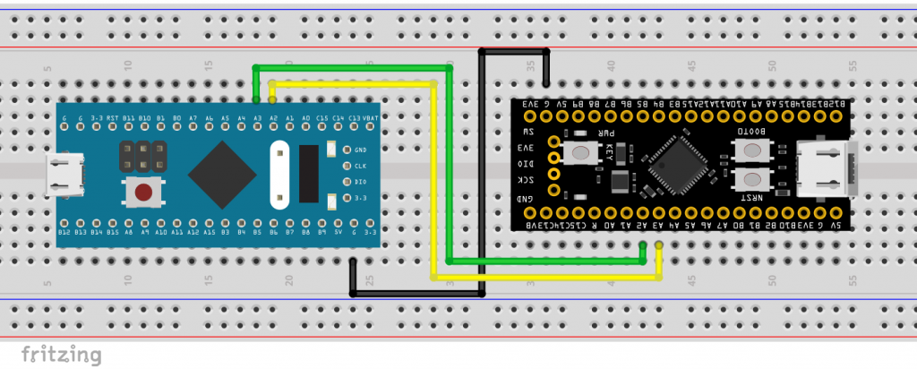
And here is the sketch that you upload to both boards:
HardwareSerial mySerial(PA3, PA2); // RX, TX

void setup() {
    Serial.begin(115200);
    mySerial.begin(115200);
}

void loop() {
    if (mySerial.available()) {
        Serial.write(mySerial.read());
    }
    if (Serial.available()) {
        mySerial.write(Serial.read());
    }
}
For each sketch you open a serial monitor and can then send messages from one monitor to the other.
Additional information: The standard serial interface of the Nucleo boards is provided by the virtual COM port of the on-board ST-LINK programmer.
Peculiarities of the Arduino GIGA R1 WIFI
If you use the Arduino GIGA R1 WIFI with the Arduino board package, the hardware serial objects and its pins are already predefined. Serial1 is assigned to RX0/TX0, Serial2 is assigned to RX1/TX1 and so on.
SoftwareSerial
The Arduino core package from stm32duino contains a SoftwareSerial library. But if possible, you should always work with the HardwareSerial interfaces. This is generally safer and saves resources.
In addition, in my experience, SoftwareSerial on the STM32 boards only runs without errors at low baud rates. On my BluePill and BlackPill boards, it only worked up to 57600, while the limit of the Nucleo-L432KC was 38400.
Nevertheless, here is an example sketch:
#include <SoftwareSerial.h>
SoftwareSerial mySerial(A5, A6); // RX, TX

void setup() {
    Serial.begin(9600);
    mySerial.begin(9600);
}

void loop() {
    if (mySerial.available()) {
        Serial.write(mySerial.read());
    }
    if (Serial.available()) {
        mySerial.write(Serial.read());
    }
}
Independent Watchdog (IWDG)
The STM32 microcontrollers have an independent watchdog (IWDG) and a window watchdog (WWDG). The IWDG is called independent because it runs completely independently of the rest of the microcontroller. It is so independent that, once started, it can no longer be stopped by software. The IWDG is controlled by a clock generator that is independent of the system clock. All this makes it extremely robust.
The window watchdog got its name from the fact that it can only be “fed” in a specific window. WWDG and IWDG trigger a reset when the timeout is reached. However, only the WWDG triggers a reset if it is fed too early.
A time period during which the watchdog may not be fed can also be defined for the IWDG. However, premature feeding (the reload) does not lead to a reset but is simply ignored. However, this forbidden window cannot be activated on all STM32 boards.
The IWDG has its own class in the STM32 board package, which is easy to use. To use the WWDG, you need to go one level deeper into the HAL functions, which is beyond the scope of this article.
IWDG example sketch
Take an STM32 board of your choice and connect a button to a suitable pin. Connect the other side of the button to GND, e.g. like this:
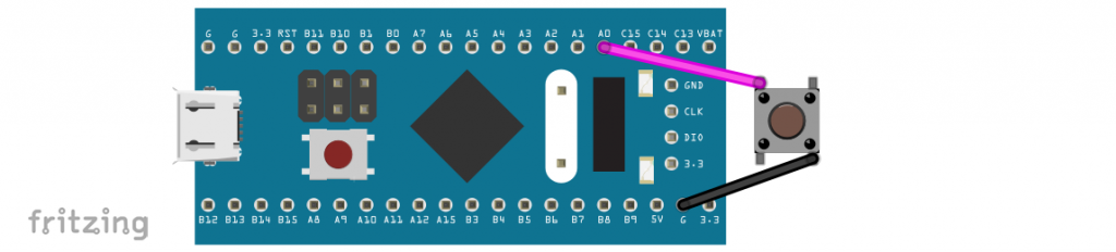
If you use a BlackPill board, you don’t need a button for the example sketch below. Instead, you can use the KEY button. It is connected between PA0 on one side and GND on the other.
The example sketch triggers a reset after 10 seconds if the IWDG has not been fed by pressing the button. After a reset caused by the IWDG, the board LED flashes briefly five times.
#include <IWatchdog.h>
const int buttonPin = PA0; // BlackPill KEY pin
const int ledPin = PC13; // Board LED

void setup() {
    pinMode(ledPin, OUTPUT);
    digitalWrite(ledPin, HIGH); // BluePill/BlackPill board LED off
    pinMode(buttonPin, INPUT_PULLUP);

    if (IWatchdog.isReset(true)) {
        // LED blinks to indicate watchdog reset
        for (uint8_t i = 0; i < 5; i++) {
            digitalWrite(ledPin, LOW);
            delay(100);
            digitalWrite(ledPin, HIGH);
            delay(100);
        }
    }

    // Init the watchdog timer with 10 seconds timeout
    IWatchdog.begin(10000000); // timeout is uint32_t
    // 10 s timeout, but ignore reload with the first 5 s
    // IWatchdog.begin(10000000, 5000000); // does not work with all STM32 MCUs

    if (!IWatchdog.isEnabled()) {
        // LED blinks indefinitely
        while (1) {
            digitalWrite(ledPin, LOW);
            delay(500);
            digitalWrite(ledPin, HIGH);
            delay(500);
        }
  }
}

void loop() {
    // Compare current button state of the pushbutton value:
    if (digitalRead(buttonPin) == LOW) {
        digitalWrite(ledPin, LOW);
        delay(1000);
        digitalWrite(ledPin, HIGH);
        // Uncomment to change timeout value to 6 seconds
        //IWatchdog.set(6000000);

        // Reload the watchdog only when the button is pressed
        IWatchdog.reload();
    }
}
Explanations for the example sketch:
The IWDG object is called IWatchdog and is predefined. Use isReset() to check whether the IWDG has triggered a reset. If you pass true to the function, the reset flag is deleted. If you pass nothing or false, the reset flag remains set.
You start the IWDG with begin(). As a parameter, you pass the timeout in microseconds. The optional second parameter defines the length of the “forbidden” window in which feeding is ignored. As already mentioned, this does not work with all STM32 boards.
Other functions used are:
isEnabled()checks whether the IWDG is active.set()allows you to redefine the timeout.- Use
reload()to feed the watchdog so that the timeout period starts again.
Real Time Clock (RTC)
The STM32 boards and the underlying microcontrollers have a real-time clock. The time is therefore not only measured (in principle, every microcontroller can do this), but also processed as year, month, day, hour, minute, and second.
The stm32duino board package does not have an integrated RTC library. I recommend using STM32duino RTC. You can install it via the library manager of the Arduino IDE.
The board package for the Arduino GIGA R1 WIFI already has the RTC functions already integrated. You can find very helpful example sketches in the user manual. In this article, I will only discuss the STM32duino_RTC library.
Every clock needs a clock source. You have three options for this:
- LSI_CLOCK (Low Speed Internal Clock): internal, rather imprecise oscillator with approx. 32 kHz. This clock is preset in the library.
- LSE_CLOCK (Low Speed External Clock): most STM32 boards have an external crystal that oscillates at 32768 Hz. These are usually very accurate. You should select this option.
- HSE_CLOCK (High-Speed External Clock): Uses the fast, external crystal on the board (usually 8 MHz).
- (HSI_CLOCK) (High-Speed Internal Clock): Fast, internal oscillator, rather inaccurate. Not supported by the library.
RTC example sketch
The library contains a number of nice example sketches. To get started, I recommend SimpleRTC.ino. I think the sketch is self-explanatory.
/*
SimpleRTC
This sketch shows how to configure the RTC and to display
the date and time periodically
Creation 12 Dec 2017
by Wi6Labs
Modified 03 Jul 2020
by Frederic Pillon for STMicroelectronics
This example code is in the public domain.
https://github.com/stm32duino/STM32RTC
*/
#include <STM32RTC.h>
/* Get the rtc object */
STM32RTC& rtc = STM32RTC::getInstance();
/* Change these values to set the current initial time */
const byte seconds = 0;
const byte minutes = 0;
const byte hours = 16;
/* Change these values to set the current initial date */
/* Monday 15th June 2015 */
const byte weekDay = 1;
const byte day = 15;
const byte month = 6;
const byte year = 15;
void setup()
{
Serial.begin(9600);
// Select RTC clock source: LSI_CLOCK, LSE_CLOCK or HSE_CLOCK.
// By default the LSI is selected as source.
//rtc.setClockSource(STM32RTC::LSE_CLOCK);
rtc.begin(); // initialize RTC 24H format
// Set the time
rtc.setHours(hours);
rtc.setMinutes(minutes);
rtc.setSeconds(seconds);
// Set the date
rtc.setWeekDay(weekDay);
rtc.setDay(day);
rtc.setMonth(month);
rtc.setYear(year);
// you can use also
//rtc.setTime(hours, minutes, seconds);
//rtc.setDate(weekDay, day, month, year);
}
void loop()
{
// Print date...
Serial.printf("%02d/%02d/%02d ", rtc.getDay(), rtc.getMonth(), rtc.getYear());
// ...and time
Serial.printf("%02d:%02d:%02d.%03d\n", rtc.getHours(), rtc.getMinutes(), rtc.getSeconds(), rtc.getSubSeconds());
delay(1000);
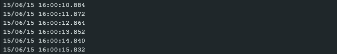
}
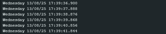
Here is the output:
It is also worth going through the other example sketches in the library. Among other things, you will learn how to program an alarm interrupt. I also recommend taking a look at the README.md of the library, as all the functions are explained there.
What I missed in the library was a routine for setting the RTC according to the compile time. The RTC is then a few seconds behind, but you are already close to the current time. I have extended SimpleRTC.ino accordingly. You can find the sketch in the appendix.
How accurate is the RTC?
The accuracy of the RTC depends on the accuracy of its clock source. With the internal oscillator (LSI), the result was miserable. The deviation in my measurements was up to one second per minute! Things were no better with the HSI clock.
The results were much better with the external quartz (LSE). The deviations were in the range of a few seconds per day – not too bad. A DCF77 module or – especially for the Arduino GIGA R1 WIFI – an NTP server would be suitable for regular adjustment.
For the BluePill and BlackPill boards, it is often recommended to remove pins PC14 and PC15 on the pin header so that the external on-board crystal can oscillate undisturbed and therefore more accurately. However, I have not investigated this further.
Low-power modes
If you want to save valuable power for battery-powered projects, there are various energy-saving modes available to you. In this regard, I recommend the STM32duino Low Power library, which you can install via the library manager of the Arduino IDE.
The available modes are:
- idle(): Low wake-up latency (µs range). Memory and power supply are retained. Minimal energy savings mainly in the core itself.
- sleep(): Low wake-up latency (µs range). Memory and power supply are retained. Minimal energy savings mainly in the core itself, but higher than in idle mode.
- deepSleep(): Average wake-up latency (ms range). Clock frequencies are reduced. Memory and power supply are retained. If supported, peripheral wake-up is possible (UART, I2C …).
- shutdown(): High wake-up latency (possibly hundreds of ms). The power supply is interrupted (except in the “always-on” area), the memory content is lost, and the system is reset.
The “wake-up methods” are:
- Defined time period,
- RTC alarm,
- external interrupt on the WakeUp pin,
- Peripheral event (UART, I2C etc.).
The low-power library is equipped with some example sketches that illustrate the various wake-up methods. Here is an example of how to wake up the board after a defined period of time:
#include "STM32LowPower.h"
const unsigned long sleepTime = 2000; // sleeping time in ms

void setup() {
    pinMode(LED_BUILTIN, OUTPUT);
    for(int i=0; i<5; i++){
        digitalWrite(LED_BUILTIN, LOW);
        delay(50);
        digitalWrite(LED_BUILTIN, HIGH);
        delay(50);
    }
    LowPower.begin();
}

void loop() {
    digitalWrite(LED_BUILTIN, LOW);
    LowPower.deepSleep(sleepTime);
    // LowPower.shutdown(sleepTime); // try this instead of deepSleep
    digitalWrite(LED_BUILTIN, HIGH);
    LowPower.deepSleep(sleepTime);
}
The sketch switches the board LED on and off every two seconds. In between, it goes into deepSleep mode. If you comment out line 17 and uncomment line 18, then it goes into shutdown mode instead, which ends with a reset. You can recognize the reset by the fact that setup()is executed and the LED flashes quickly.
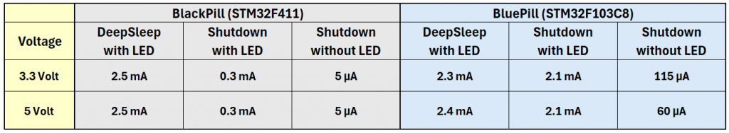
Power consumption in sleep mode
I carried out a few current measurements in deepSleep and Shutdown mode with BluePill and BlackPill boards.
As the power consumption of the power LED is particularly noticeable in shutdown mode, I first carried out the tests in this mode with the LED, then I removed the LED from the board and tested again.
On Nucleo boards, the ST-LINK programmer consumes a significant amount of power. You can disconnect it by setting certian solder bridges, but I simply didn’t feel like trying it out. I also didn’t take a close look at the Arduino GIGA R1 WIFI in this respect.
Appendix – Extended RTC sketch
I have extended the example sketch SimpleRTC.ino so that it sets the RTC according to the time of compilation. This time is stored in the character strings __DATE__ and __TIME__. Example: “Aug 11 2025” and “22:17:25”. It is relatively easy to extract the year, day, hours, minutes and seconds from this. For example, __TIME__[1] is the second digit of the hours, but as an ASCII code (e.g. 2 = ASCII code 50). Therefore, the ASCII code of 0 (= 48) is substracted → __TIME__[1] – ‘0’.
The month is determined by a simple string comparison. Calculating the day of the week is a little more difficult. Thank goodness clever people have already thought about this. You find more on this topic in this Wikipedia article. I use Tomohiko Sakamoto’s algorithm. However, it returns the days of the week as numbers from 0 (= Sun) to 6 (= Sat), whereas the STM32duino RTC-Lib defines numbers from 1 (= Mon) to 7 (= Sun). This is adjusted by line 41.
I then added a function to set the time more precisely. To do this, set “No end of line” in the serial monitor. Then enter the time in the format hh:mm:ss.
#include <STM32RTC.h>

#define MONTH_IS(str) (__DATE__[0] == str[0] && __DATE__[1] == str[1] && __DATE__[2] == str[2])

/* get month from __DATE__ */
#define BUILD_MONTH ( \
    MONTH_IS("Jan") ?  1 : \
    MONTH_IS("Feb") ?  2 : \
    MONTH_IS("Mar") ?  3 : \
    MONTH_IS("Apr") ?  4 : \
    MONTH_IS("May") ?  5 : \
    MONTH_IS("Jun") ?  6 : \
    MONTH_IS("Jul") ?  7 : \
    MONTH_IS("Aug") ?  8 : \
    MONTH_IS("Sep") ?  9 : \
    MONTH_IS("Oct") ? 10 : \
    MONTH_IS("Nov") ? 11 : \
    MONTH_IS("Dec") ? 12 : 0 )

/* get day and year from __DATE__ */
#define BUILD_DAY  (((__DATE__[4] == ' ') ? 0 : __DATE__[4] - '0') * 10 + (__DATE__[5] - '0'))
#define BUILD_YEAR  ((__DATE__[7]-'0') * 1000 + (__DATE__[8]-'0') * 100 + (__DATE__[9]-'0') * 10 + (__DATE__[10]-'0'))
/* get hour, minute and second from __TIME__ */
#define BUILD_HOUR  ((__TIME__[0]-'0')*10 + (__TIME__[1]-'0'))
#define BUILD_MIN   ((__TIME__[3]-'0')*10 + (__TIME__[4]-'0'))
#define BUILD_SEC   ((__TIME__[6]-'0')*10 + (__TIME__[7]-'0'))

#define SAKAMOTO_T(m) \
  ((m)==1?0:(m)==2?3:(m)==3?2:(m)==4?5:(m)==5?0:(m)==6?3:\
   (m)==7?5:(m)==8?1:(m)==9?4:(m)==10?6:(m)==11?2:(m)==12?4:0)

/* Sunday = 0, ..., Saturday = 6 (Original-Sakamoto) */
#define WD_SUN0(y,m,d) \
  (((((y) - ((m) < 3))                                         \
    + (((y) - ((m) < 3)) / 4)                                  \
    - (((y) - ((m) < 3)) / 100)                                \
    + (((y) - ((m) < 3)) / 400)                                \
    + SAKAMOTO_T(m) + (d)) % 7))

/* Needed for the STM32 RTC lib: Monday = 1, ..., Sunday = 7 */
#define WD_MON1(y,m,d)  ((((WD_SUN0((y),(m),(d)) + 6) % 7) + 1))
#define BUILD_WEEKDAY  WD_MON1(BUILD_YEAR, BUILD_MONTH, BUILD_DAY)

char daysOfTheWeek[7][12] = {"Monday", "Tuesday", "Wednesday", "Thursday", "Friday", "Saturday", "Sunday"};

/* Get the rtc object */
STM32RTC& rtc = STM32RTC::getInstance();

/* time and date variables */
byte seconds = BUILD_SEC;
byte minutes = BUILD_MIN;
byte hours = BUILD_HOUR;
byte weekDay = BUILD_WEEKDAY;
byte day = BUILD_DAY;
byte month = BUILD_MONTH;
byte year = BUILD_YEAR - 2000;

void setup() {
    Serial.begin(115200);

    // Select RTC clock source: LSI_CLOCK, LSE_CLOCK or HSE_CLOCK.
    // By default the LSI is selected as source.
    rtc.setClockSource(STM32RTC::LSE_CLOCK);

    rtc.begin(); // initialize RTC 24H format

    // Set the time
    rtc.setHours(hours);
    rtc.setMinutes(minutes);
    rtc.setSeconds(seconds);

    // Set the date
    rtc.setWeekDay(weekDay);
    rtc.setDay(day);
    rtc.setMonth(month);
    rtc.setYear(year);

    // you can use also
    //rtc.setTime(hours, minutes, seconds);
    //rtc.setDate(weekDay, day, month, year);
}

void loop() {
    static unsigned long lastPrint = 0;

    if (millis() - lastPrint >= 1000){
        // Print date...
        Serial.printf("%s %02d/%02d/%02d ", daysOfTheWeek[weekDay-1], rtc.getDay(), rtc.getMonth(), rtc.getYear());
        // ...and time
        Serial.printf("%02d:%02d:%02d.%03d\n", rtc.getHours(), rtc.getMinutes(), rtc.getSeconds(), rtc.getSubSeconds());
        lastPrint = millis();
    }

    if (Serial.available()){  // set serial monitor to "No Line Ending"
        hours = Serial.parseInt();
        minutes = Serial.parseInt();
        seconds = Serial.parseInt();
        rtc.setTime(hours, minutes, seconds);
    }
}
The output should then look like this: