About the post
In my last post, I dealt with infrared (IR) proximity sensors. In this post, I would like to stick to the topic of infrared, but this time it is about IR remote controls. At first, I will go into the transmission technique via IR in detail. Then I will explain how to build IR remote controls yourself. Finally, I would like to show you how you can remotely control your projects with an IR remote control using a suitable library. Of course, you can also go straight to the last chapter if you are less interested in the background or if you don’t have time.

IR data transmission
As most people surely know, infrared radiation is invisible light. The infrared spectrum joins the visible spectrum in the longer wavelength range. Infrared radiation is also known as heat radiation. You can find out more about infrared radiation in general, e.g., here on Wikipedia.
Since every warm body emits more or less infrared light depending on its temperature, IR radiation is omnipresent. This can affect targeted signal transmissions. IR remote controls use a trick by sending pulsed signals. As a result, the signals differ significantly from the ambient radiation, which can be filtered out accordingly. Most often, IR remote controls use a pulse rate of 38 kilohertz.
Infrared receivers
Infrared radiation can be detected using IR-sensitive photodiodes. I described this type of IR sensors in my last post. You may have seen them as “flame sensors” on corresponding modules.

With such photodiodes, however, one captures the entire IR radiation, whether pulsed or non-pulsed. If you only want to fish the pulsed radiation out of the “soup” of infrared light, you must use such three-pin ones:
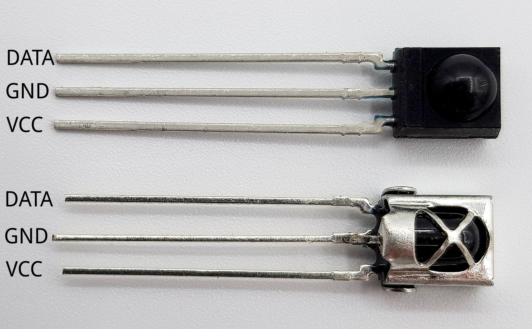
You can find these receivers under the designation VS1838B or TSOPxx38 with xx = z.B. 18, 22, 24, 48. If the designations do not end with 38, as e.g. TSOP2256, then the pulse frequency is not 38 kHz, but in this example 56 kHz. An overview of the nomenclature of IR receivers can be found here.
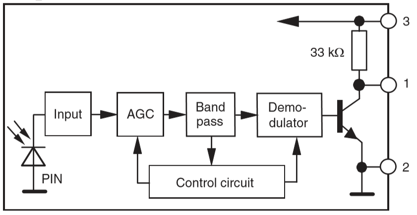
Also, a receiver for pulsed signals contains a normal IR photodiode (see diagram below). The AGC unit (automatic gain control) amplifies the signal. The bandpass filter cleans it and finally the demodulator converts it into a continuous signal (continuously relating to the 38 kHz). At the end there is a transistor, which switches to Ground in case of an incoming signal. This means that pin 1 of the receiver changes from HIGH to LOW. Note: not all IR receivers have the same pin assignment – look at the data sheet. Also in the Fritzing schematic below I have a different assignment (because I only found this one).
IR remote controls: analysis of signals
I would now like to show how you can analyze an IR signal. Further down, I use a more comfortable library. But I find it quite exciting to do it “manually”.
But first the wiring. First we will concentrate on the receiver part (at pin 2), the transmitter part (at pin 5) will be discussed later.
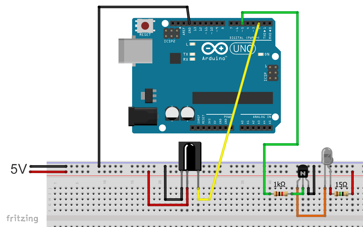
GND of the receiver is connected to GND, VCC to 5 volts and DATA to an I/O pin (I chose pin 2). The receiver can also be attached directly to the 5V supply of the Arduino because it draws less than 1 mA of electricity.
Structure of IR remote control signals
Signals from IR remote controls are double pulsed, so to speak. A signal consists of a sequence of pulses, each pulse having a width of several hundred microseconds to a few milliseconds. I call these pulses main pulses because I couldn’t think of anything better. So, that is not a technical term. Different lengths of pauses are between the main pulses. The main pulses in turn consist of many 38 kHz pulses.
Here is a typical example of an IR signal:
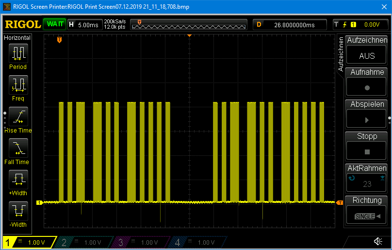
The main pulses are easily recognizable. You also see that the signal basically consists of two identical main pulse sequences separated by a longer pause. This is not uncommon with IR remote controls.
At higher resolution, the 38 kHz pulses within main pulses are then revealed. Here is an example of a magnified main pulse:

On the receiver side, the 38 kHz pulses are demodulated. In addition, the signal is reversed due to the set-up of the receivers described above. That is, LOW becomes HIGH and vice versa. Here you can see again the signal from the penultimate picture, but at the receiver:

The evaluation sketch for signals on the receiver
The evaluation is about measuring the pulse and pause widths. The best way to do this is to first define a suitable unit of time (“timeSegment”) that represents the resolution. In the following sketch, the Arduino checks whether the data pin on the IR receiver is HIGH or LOW after each time unit expires. The time units are added until a HIGH/LOW or LOW/HIGH change takes place. This is how you move through the signal piece by piece.
The counter for the pulse width (or pause width) is defined as pulseWidthCounter in the sketch. The pulse pause pairs are stored as an array (irSignal). The pairs are counted by the pulseCounter. The end of a signal is reached when there is no pulse for a long time (maxCount is reached).
There are two things to consider in this procedure:
- Checking the pin status using digitalRead is quite slow with about three microseconds (at least using the Arduino UNO). The direct query of the input register via (PIND & (1<<PD2)) is much faster.
- If timeSegment is too small, the pin status must be queried very often. The time required for reading the pin status, even with the fast method, then adds up to a significant error. If timeSegment is too large, beginning and end of the pulses become correspondingly blurred. Twenty microseconds have proven themselves.
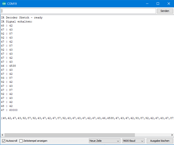
If a signal is fully transmitted, it is output once on the serial monitor in pairs and once as an array. You can copy the latter directly into the transmitter sketch that we are discussing in a moment. The last measured value is maxCount. We do not need this because it is no longer part of the signal. Accordingly, I omit it in the array output.
unsigned int pulseWidthCounter, pulseCounter;
unsigned int maxCount = 60000;
const int timeSegment = 20;
bool completed;
unsigned int irSignal[100][2];

void setup() {
  Serial.begin(9600);
  Serial.println("IR Decoder Sketch - ready");
}

void loop() {
  pulseCounter = 0;
  if(!(PIND & (1<<PD2))){
    completed = false;

    while(!completed){

      pulseWidthCounter = 0;
      while(!(PIND & (1<<PD2))){
        pulseWidthCounter++;
        delayMicroseconds(timeSegment);
      }
      irSignal[pulseCounter][0] = pulseWidthCounter;

      pulseWidthCounter = 0;
      while((PIND & (1<<PD2)) && (pulseWidthCounter < maxCount)){
        pulseWidthCounter++;
        delayMicroseconds(timeSegment);
      }
      irSignal[pulseCounter][1] = pulseWidthCounter;
      if(pulseWidthCounter >= maxCount){
        completed = true;
      }

      pulseCounter++;
      if(pulseWidthCounter >= maxCount){
        completed = true;
      }
    }

    Serial.println("IR Signal erhalten:");
    for(int i=0; i<pulseCounter; i++){
      Serial.print(irSignal[i][0]);
      Serial.print(" | ");
      Serial.println(irSignal[i][1]);
    }
    Serial.println();
    Serial.print("{");
    for(int i=0; i<(pulseCounter-1); i++){
      Serial.print(irSignal[i][0]);
      Serial.print(",");
      Serial.print(irSignal[i][1]);
      Serial.print(",");
      if(i==(pulseCounter-2)){
        Serial.print(irSignal[i+1][0]);
      }
    }
    Serial.println("}");
  }
}
The output on a concrete example
For testing, I have selected the remote control of my satellite receiver. In fact, the “Channel+” button. Incidentally, I also used this signal for the oscilloscope measurements above. To calculate the pulse widths in microseconds from the numbers, you must of course multiply them by twenty. But I found it easier to work with the smaller numbers.
Build your own IR remote controls
And now we can take the signal that has just been analyzed and send it with an IR LED. We build our own remote control or simulate the existing remote control. But first I have to explain how to generate a 38 kHz signal.
Generating a 38 kHz pulse signal
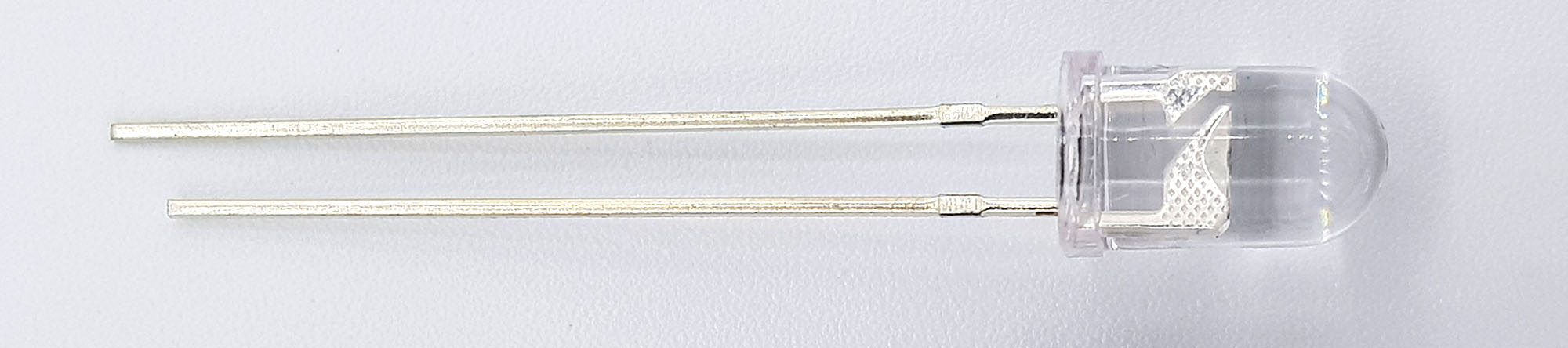
IR LEDs
As an infrared source, you best use an IR LED. It basically works like an LED for visible light. IR LEDs are also available in different “colors”, i.e. in different wavelengths. 850 or 940 nm are the common wavelengths. According to my research, 940 nm seems to fit better to most receivers. Otherwise, the IR LEDs differ mainly in their maximum current. The IR LEDs I use have a current of 100 mA at 1.2 to 1.5 volts. When selecting resistors, it should be noted that for pulsed signals effectively only half the current is needed. In addition, the IR signals are very short. Nevertheless, you should consider using an external power source and switching it on with a transistor like in my circuit above. As a series resistor I used 15 ohms.
Generating pulse signals with IR LEDs
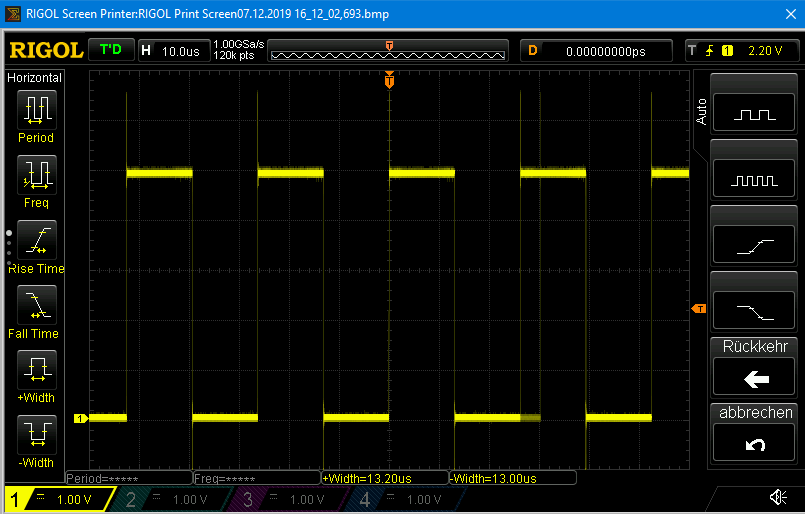
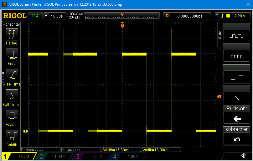
To let the IR LED pulse with 38 kHz, one can theoretically use the function tone(pin, frequency) or noTone(). More information about this feature can be found here. For tone() you have to choose a PWM-enabled pin. In fact, with tone(5, 38000) I could generate beautiful pulses of the correct width at pin 5:
I had already been able to use the tone() function successfully in my last article about self-built proximity sensors. So, I wanted to generate my signal with a construction like: tone – delay – noTone – delay. But for reasons that I am obscure, it did not work. Does anyone have an idea? Do the tone/ noTone commands take too much time? By the way, the variant tone(pin, frequency, length), i.e. without delay and noTone does not work either because length is given in milliseconds, which is too rough for this purpose.
However, there are still two alternatives that work. Either you create the signals via the digitalWrite function or via the faster variant of direct port access. Here’s the sketch:
const int irLEDPin = 5;

void setup() {
  pinMode(irLEDPin, OUTPUT);
}

void loop() {
  //PORTD |= (1<<PD5);                // much faster than digitalWrite
  digitalWrite(irLEDPin, HIGH);   // too slow: 3 microseconds (Arduino UNO / Atmega 328P)
  delayMicroseconds(13);            // does not work - switch to 10 or 9 µs
  //PORTD &= ~(1<<PD5);
  digitalWrite(irLEDPin, LOW);    // again 3 microseconds
  delayMicroseconds(13);            // does not work - switch to 10 or 9 µs
}
If you opt for digitalWrite, you’ll have to reduce the delays from 13 microseconds to 10 microseconds, as the digitalWrite function requires about 3 seconds (at least on the Arduino UNO). Otherwise, this happens:
If you choose the variant with direct access, you can stay at 13 µs. The results of the measurements would even suggest taking 14 µs (see next picture). Interestingly, a microsecond seems to be swallowed somewhere!? Can anyone explain this to me? No matter, I left it at 13 microseconds and it worked.

There are other methods to generate fast PWM signal (via the internal timers of the AVR MCUs), but this would lead too far here.
The transmitter sketch
The following sketch simulates the “Channel +” button of my remote control. The circuit still corresponds to the Fritzing scheme from above. The channel is incremented every ten seconds. An automatic zapper, so to speak. Pretty simple, but I would just like to showcase the principle. If you implement more signals and then assign them to buttons, you can recreate an entire remote control in this way.
The sketch should not be difficult to understand. The previously decoded signal is used. The length of the array is determined by its size in bytes. I borrowed and modified the pulseIR function from an Adafruit tutorial.
I’ve tried it all and it works.
const int timeSegment = 20;
const int irLEDPin = 5;
int irSignal[] = {48,42,47,43,92,87,92,43,47,42,47,87,92,43,47,43,47,42,47,43,46,4538,47,43,47,42,93,87,92,42,47,43,47,87,92,42,47,43,47,42,48,42,47};

int irSignalLength;
unsigned long phase;

void setup() {
  irSignalLength = sizeof(irSignal)/2; // One int = Two bytes
  pinMode(irLEDPin, OUTPUT);
}

void loop() {
  int i = 0;

  phase = 20*irSignal[i];
    pulseIR(phase);
    i++;
  do{
    phase = 20*irSignal[i];
    delayMicroseconds(phase);
    i++;
    phase = 20*irSignal[i];
    pulseIR(phase);
    i++;
  }while(i<irSignalLength);

  delay(10000);
}

void pulseIR(long microsecs) {
  cli();  // interrupts switched off

  while (microsecs > 0) {
  // 38 kHz is about 13 microseconds high and 13 microseconds low
  PORTD |= (1<<PD5);                // much faster than
  //digitalWrite(irLEDPin, HIGH);   // too slow: 3 microseconds (Arduino UNO / Atmega 328P)
  delayMicroseconds(13);            // 10 microseconds, if you chose digitalWrite
  //digitalWrite(irLEDPin, LOW);    // again 3 microseconds
  PORTD &= ~(1<<PD5);
  delayMicroseconds(13);            // 10 microseconds, if you chose digitalWrite
  microsecs -= 26;
  }

  sei();  // interrupts switched on
}
IR remote controls with the IRLib2 library
Most of you will want to use IR remote controls to remotely control projects. The procedure explained so far is a little complex. There is also the question of how to judge whether a signal matches a reference. Because if you record a signal several times, you will see that the measured length of the individual pulses varies somewhat.
Smart people have developed libraries for the detection and coding of signals from IR remote controls. These are based on the fact that the signals of IR remote controls can be assigned to specific protocols, such as NEC, Sony, Panasonic, etc. These have certain patterns and allow the signal sequences to be represented in a compact value instead of an unwieldy array.
There are a number of good libraries. The classic is IRRemote by Ken Shirriff. Personally, however, I recommend the LIBRARY IRLib2, as it is compatible with a variety of boards. When installing, it should be noted that the library is actually a collection of libraries. Therefore, if you download the zip file, you must not unzip it directly in the library folder. Instead, you unzip the zip file somewhere and then copy the main folders to the Arduino library directory. The library cannot be installed via the convenient Arduino library manager.
A good tutorial about the library can be found here on the Adafruit learning web pages. I would just like to give a brief introduction in this post.
IR remote controls: decode signals with IRLib2
After installing the library, take the example sketch dump.ino without further adjustment. The circuit needed for the sketch is still the same as at the beginning of this article.
/* dump.ino Example sketch for IRLib2
   Illustrates how to receive an IR signal, decode it and print
   information about it to the serial monitor.
*/
//This includes everything. Not generally recommended.
//It's better to include only the parts of library you really need.
//But for this example it's quick and easy. See "comboDump" example
//for a more efficient way.
#include "IRLibAll.h"

IRrecvPCI myReceiver(2); //create receiver and pass pin number
IRdecode myDecoder;   //create decoder

void setup() {
  Serial.begin(9600);
  delay(2000); while (!Serial); //delay for Leonardo
  myReceiver.enableIRIn(); // Start the receiver
  Serial.println(F("Ready to receive IR signals"));
}

void loop() {
  //Continue looping until you get a complete signal received
  if (myReceiver.getResults()) {
    myDecoder.decode();           //Decode it
    myDecoder.dumpResults(true);  //Now print results. Use false for less detail
    myReceiver.enableIRIn();      //Restart receiver
  }
}
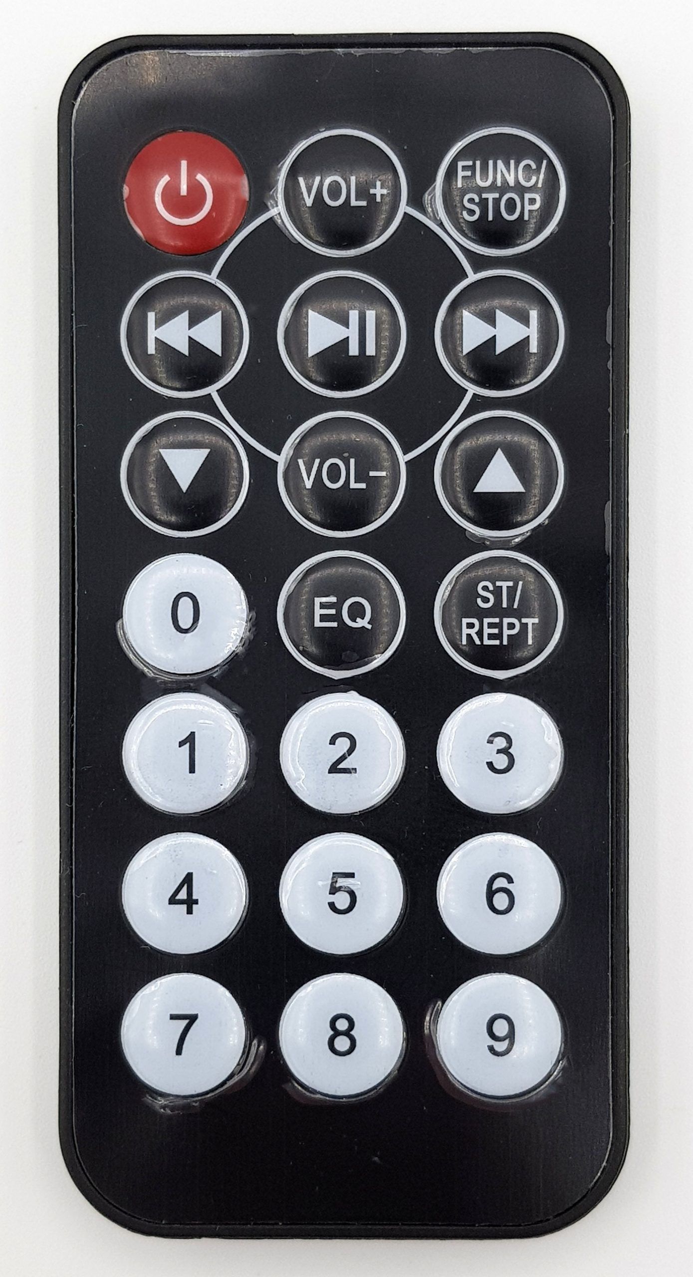
As a remote control I have chosen a very handy and cheap model. Such remote controls are available in a wide selection on Amazon or eBay:
Then I decoded the signals of keys 1, 2 and 3. Here is the output of the dump.ino sketch for the key 1:
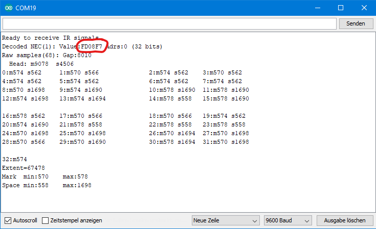
The relevant output is the “Value” (marked in red), in this case FD08F7. That’s a bit more affable than the long series of numbers before, isn’t it?
A simple application example
With the appropriate codes you can then remotely control everything controllable, be it lamps, cars, music or whatever. Here is a minimal example where one of three LEDs is switched on with my remote control, an LED zapper, so to speak.
#include "IRLibAll.h"

IRrecvPCI myReceiver(2);
IRdecode myDecoder;
const int led1 = 10;
const int led2 = 11;
const int led3 = 12;

void setup() {
  pinMode(led1,OUTPUT);
  pinMode(led2,OUTPUT);
  pinMode(led3,OUTPUT);
  myReceiver.enableIRIn(); // Start the receiver
}

void loop() {
  if (myReceiver.getResults()) {
    myDecoder.decode();           //Decode it
    switch(myDecoder.value){
      case 0xFD08F7:
        switchOnLed(led1);
        break;
      case 0xFD8877:
         switchOnLed(led2);
        break;
      case 0xFD48B7:
         switchOnLed(led3);
        break;
    }
  }
  myReceiver.enableIRIn();      //Restart receiver
}

void switchOnLed(int pin){
  digitalWrite(led1, LOW);
  digitalWrite(led2, LOW);
  digitalWrite(led3, LOW);
  digitalWrite(pin, HIGH);
}
And here is the corresponding circuit:

Another suggestion
Some time ago I wrote a post entitled “Own radio protocols“. This involved communication with 433 MHz modules using specially developed protocols. The methodologies presented there can be transferred to infrared technology. So, you can then send e.g. text, measurement results or the like. Have a look if you are interested.
Acknowledgement
The remote control in the post image is from hojun Kang on Pixabay. The Arduino in the background of the post image is from Seven_au, also Pixabay. However, I still blurred the picture. I owe the remote control collection to Mirko Maibach on Pixabay.
I thank Chris Young (cyborg5) for his library and tutorial.
at the begining of the article ‘analysis of signals’
can i ask how you are ‘manually’ viewing the remote control signals on the osciliscope
are you simply tapping the signal via the IR reciver output leg/uno pin2 node
thanks
It is quite a while since I wrote this article. I have just tried it again for the receiver signal. I connected the IR receiver to 5V. Then I connected the GND pin of the receiver to GND of my oscilloscope and the data pin of the receiver to the voltage pin of my oscilloscope. No Arduino needed for this. I am not sure anymore how I managed measuring the transmitter signal. I assume I connected the oscilloscope to GND and the transistor base.
> I had already been able to use the tone() function successfully in my last article about self-built proximity sensors. So, I wanted to generate my signal with a construction like: tone – delay – noTone – delay. But for reasons that I am obscure, it did not work. Does anyone have an idea?
Yes, I do. Arduino’s tone() function has significant overheads. There are some cycles wasted on abstractions as they are common in the Arduino library – such as reading register addresses from program memory (cf. e.g. toneBegin() which does a linear search on a lookup table) and register operations that are turned into function calls. Also, some setup operations are redundant, when the pin argument doesn’t change.
What introduces the most overheads are all the divisions in the tone() function, though. Since the ATmega328p (and AVRs in general) doesn’t have a divide instruction, division has to be done in software. In the worst case, when the compiler doesn’t see a constant divisor (as with tone()), this translates into calls to a generic divide functions such as `__divmodsi4`.
In a quick test, I’m observing that a single tone() call adds 10 ms or so over directly configuring the registers for enabling PWM mode on a pin. (using a 8 MHz Arduino Mini Pro)
For comparison, see also a simple example of mine, where the invariant PWM setup (for the carrier frequency) is done once and enabling/disabling the PWM pin during the transmission of a raw IR remote control code just takes 3 cycles or so: https://gist.github.com/gsauthof/144e8fc4df89cf1d8cdaad8be3accda1
> Do the tone/ noTone commands take too much time?
It’s only the tone() function that has these high setup costs.
Great thanks for the explanation – this makes sense. 10 ms – that’s ages! Not particularly efficient. Thanks for the clarification.