About the post
In many articles, including my last one on IR remote controls, I have used logical operations and port manipulation. By this I mean expressions such as PORTD |= (1<<PD2) instead of digitalWrite(2, HIGH). In this article, I would like to address this issue separately.
Granted, this is a little “dry”. It doesn’t really get interesting until you apply it. So far, however, due to the size of this topic there has been no room for it in my posts so far. So consider this post as a kind of reference that I will refer to when I use binary logic and port manipulation again.
I will start with logical operations (bitwise operations) and then turn to the ports of the ATmega328P and port manipulation. Then I’ll have a little practical exercise for you. Finally, there is a speed comparison and I answer the question of why port manipulation is so much faster.
Why are logical operations and port manipulation relevant?
Port manipulation, i.e. direct access to Arduino pins (or other boards or microcontrollers) via its ports, is much faster than the usual Arduino functions. Most of the time it doesn’t matter, but sometimes it does. And the logical operations with their bitwise operators are the tool for this. The grammar, so to speak.
Actually, I don’t really like the term “port manipulation”. It sounds like it would be forbidden. Basically, however, it is the more natural way to program microcontrollers. digitalWrite, pinMode and Co, on the other hand, actually obscure the view of what is actually happening at the hardware level.
Logical Operations come into play even when you are generally involved in programming registers, such as in sensors. One often has to deal with tasks such as “write 101 into the bits 3-5 of the register XY”. This can only be reasonably done with logical (bitwise) operations.
Logic operations: the bit operators
Bit operators and shift operators
The main bit operators are:
- & logical AND UND
- | logical OR
- ^ exclusive OR (XOR)
- ~ negation (NOT)
A major difference from the usual operators such as plus or minus is that the bit operators are applied bit by bit. The shift operators are:
- >> right shift
- << left shift
Bit operator AND (&)
The bit operator AND checks whether the two operands are 1 (true). If this is the case, then the result is 1, otherwise 0 (false).
0 & 0 = 0
1 & 0 = 0
0 & 1 = 0
1 & 1 = 1
Applied to bytes:
0b10011100 & 0b01010111 = 0b00010100
Bit operator OR (|)
The bit operator OR checks whether at least one of the two operands is 1 (true). If so, then the result is 1, otherwise 0.
0 | 0 = 0
1 | 0 = 1
0 | 1 = 1
1 | 1 = 1
Applied to bytes:
0b10011100 | 0b01010111 = 0b11011111
Bit operator XOR (^)
The bit operator XOR checks whether exactly one of the two operands is 1. If this is the case the result is 1, otherwise it is 0. In contrast to OR this operator delivers 0 even if both operands are 1.
0 ^ 0 = 0
1 ^ 0 = 1
0 ^ 1 = 1
1 ^ 1 = 0
Applied to bytes:
0b10011100 ^ 0b01010111 = 0b11001011
Bit operator NOT (~)
The bit operator NOT has only one operand. NOT reverses the value, so 1 (true) becomes 0 (false) and vice versa.
~0 = 1
~1 = 0
Applied to bytes:
~0b10011100 = 0b01100011
Shift operators
Shift operators shift a number bitwise to the right or left. A shift of x digits to the left corresponds to a multiplication of 2x. A shift of x digits to the right corresponds to a division by 2x.
Shifting to the right eliminates all digits that are moved behind the first digit (LSB = least significant bit). Moving to the left eliminates all digits that are outside the value range of the variable (beyond the MSB = most significant bit).
(0b1 << 1) = 10
(0b101 << 1) = 1010
(0b111 >> 1) = 11
(0b11110000 << 1) = 0b11100000 // if 0b11110000 has been defined as byte
There are a few pitfalls. What will be the output of the following sketch shiftoperator_test.ino?
byte a,b,c;
unsigned int d;
int e;

void setup() {
  Serial.begin(9600);
  a = 0b1111;
  b = a<<5;
  c = a>>1;
  d = a<<5;
  e = a<<12;
  Serial.print("a = "); Serial.println(a, BIN);
  Serial.print("b = "); Serial.println(b, BIN);
  Serial.print("c = "); Serial.println(c, BIN);
  Serial.print("d = "); Serial.println(d, BIN);
  Serial.print("e = "); Serial.println(e, BIN);
  Serial.print("e(dezimal) = "); Serial.println(e);
}

void loop() {}
Here’s the (expected?) result, if you are using an AVR based board. In case you use a SAMD or ESP32 based board try and replace e = a<<12 by e = a<<28 and see what happens.

The ports of the Arduino UNO
The Arduino UNO has fourteen digital I/O pins (0 – 13) and the six “quasi-analog” I/O pins A0 to A5. If you look at the data sheet of the ATmega328P, the core of the Arduino, you will find the pins in a different organizational structure.

The I/O pins are organized in ports B, C and D. The pin designations are correspondingly PBx, PCx and PDx with x = 0 to a maximum of 7. For these groups there are three 8 bit registers, which I will discuss in a moment, namely DDRx, PORTx and PINx with x = B, C or D.
The pins PB6 and PB7 are not accessible when using the Arduino UNO because the 16 MHz clock is hard-wired to them. PC6 is set as reset on the Arduino board and is therefore not accessible as an I/O pin. PC7 simply does not exist.
The data direction registers DDRx
If you want to use an I/O pin as input or output, you do this setting in the “Arduino language” via the pinMode function. In the ATmega328P, the corresponding bits are set in the relevant direction register (DDR = Data Direction Register). Here is the structure of the direction register for port B as an example:
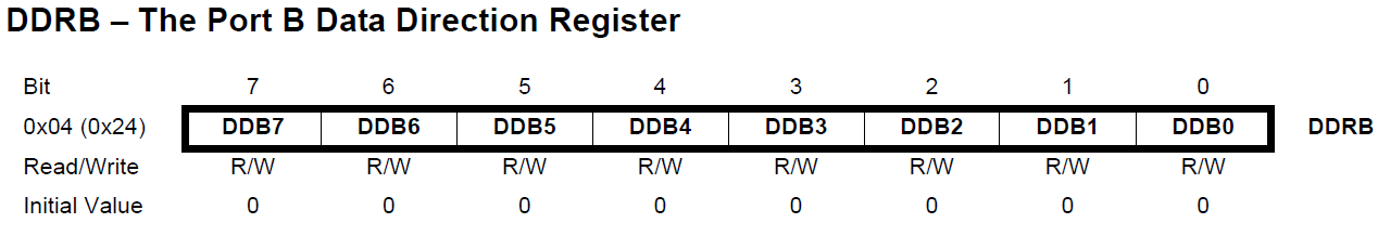
As an example, I would like to set the digital pin 13 of the Arduino to OUTPUT. This corresponds to pin PB5 according to the pinout scheme from above. This means that bit No. 5 must be set in the DDRB register. Access to the register is easy. The following assignment is sufficient:
DDRB = 0b100000 or DDRB = 0x20 or DDRB = 32
It’s that easy because “DDRB” contains the necessary instructions via a #define statement in the AVR libraries (avr/io.h –> avr/iom328p.h):
#define DDRB _SFR_IO8(0x04)
If you want to set several pins of port B to OUTPUT, e.g. pin 5 and pin 3, then the statement looks like this:
DDRB = 0b101000, or hexadecimal: DDRB = 0x28, or decimal: DDRB = 40
The port data register PORTx
If you want to set an I/O pin that you had previously set to OUTPUT into the HIGH state, you will access the responsible port data register (PORTx) as part of port manipulation. Here PORTB as an example:

A pin is HIGH if you have set the corresponding bit. To stick to the example above of Arduino pin 13:
PORTB = 0b100000 equals digitalWrite(13, HIGH)
Stop! Of course, the equivalence only applies to the effect on pin 13 (PB5) because the first assignment switches all other PORTB pins to LOW. On the other hand, digitalWrite is selective.
The Port Input Pin Register PINx
You can query the state, i.e. LOW or HIGH, of an input pin via the corresponding PINx (x = B, C, D) register. For Arduino Pin 13 for example:
PINB == 0b100000 instead of digitalRead(13)
Here, too, the restriction applies that digitalRead is selective while the PINB query in this form checks whether only PB5 is HIGH.
Use of logical operations in port manipulation
Selective setting of bits
To selectively set a single or multiple bits, one uses the logical OR. For example, you can set PB5 to HIGH without affecting the remaining pins of the PORTB
PORTB = PORTB | 0b100000 or PORTB |= 0b100000 or, preferrably:
PORTB |= (1<<PB5)
PB5 is simply defined as 5 by a #define assignment. So, you might as well write PORTB |= (1<<5). You could even replace PB5 with PC5 or PD5. Of course, this would not be easy to read.
Several bits, such as PB5 and PB3, are set as follows:
PORTB |= (1<<PB5) | (1<<PB3) because:
(1<<PB5) | (1<<PB3) = 0b100000 | 0b1000 = 0b101000
Occasionally, you will also find _BV(x) instead of (1<<x). “BV” stands for bit value. Both are identical as a look into the library file sfr_defs.h shows:
#define _BV(bit) (1 << (bit))
Selective deletion of bits
The selective deletion of bits is also simple, but it is not necessarily obvious at first sight. Again, I take PB5 as an example:
PORTB &= ~(1<<PB5), synonymous with:
PORTB &= ~(0b100000) or PORTB &= 0b11011111
Of course, you can also delete several bits simultaneously, here for example PB3 and PB5:
PORTB &= ~((1<<PB5)|(1<<PB3))
Selective inverting of bits
The logical XOR is suitable for inverting individual bits. One takes advantage of the fact that ^1 turns 1 to 0 and vice versa. ^0, on the other hand, is neutral. This way you invert PB5 selectively:
PORTB ^= (1<<PB5)
Or, if multiple bits shall be inverted:
PORTB ^= (1<<PB5)|(1<<PB3)
If you want to invert an entire port, two variants are possible:
PORTB = ~PORTB or PORTB ^= 0b11111111
Selectively querying pin states
This is no surprise. The expression
PINB & (1<<PB5)
returns 0, i.e. false if PB5 is LOW. If PB5 is HIGH, then the expression is unequal to zero, i.e. true. The exact value, here 0b100000, i.e. 32, is not relevant.
A little exercise sketch
Now you can try it out if you want. For this purpose, build the following circuit:
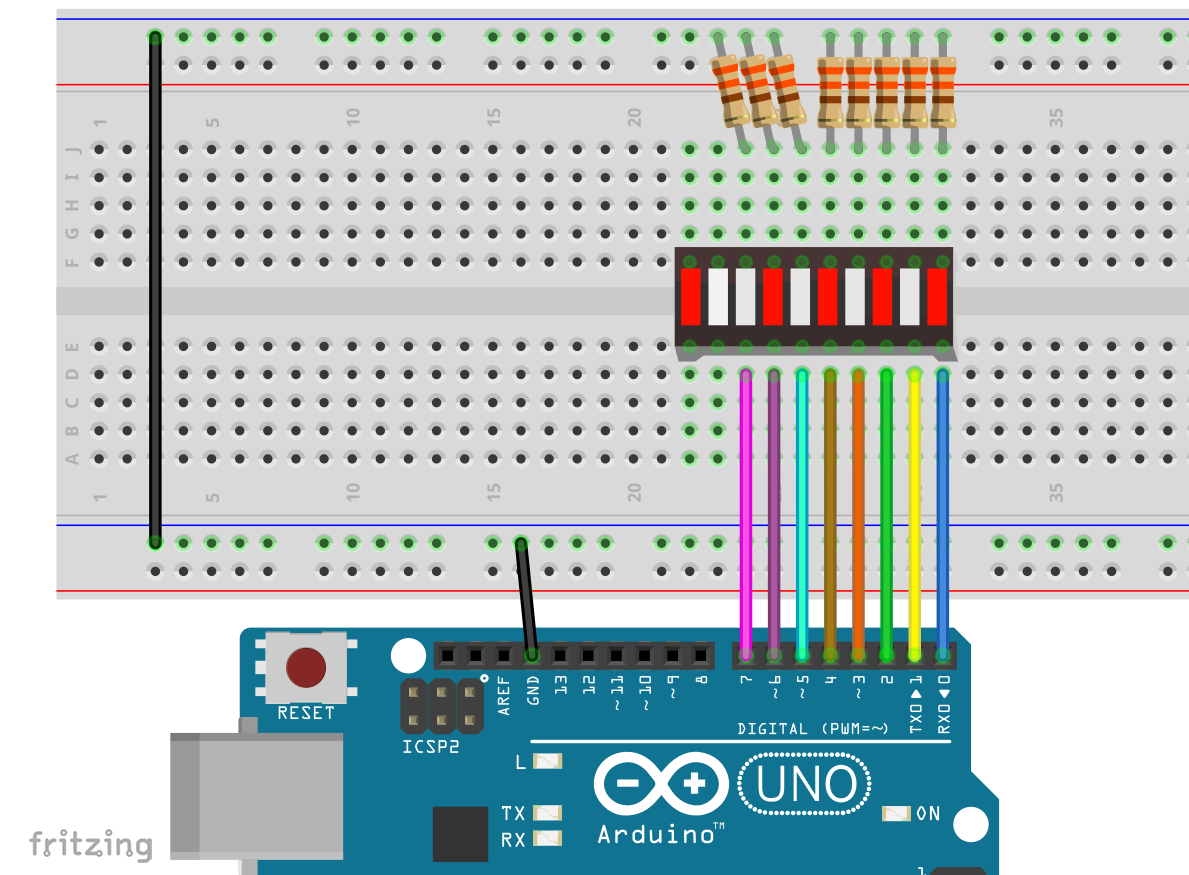
Then try the following sketch and play around with it a bit. Does it do what you have expected?
int dTime = 2000; //delay time

void setup(){
  DDRD = 0xFF;
}

void loop() {
  PORTD = 0b10101010;
  delay(dTime);
  PORTD |= (1<<PD6);
  delay(dTime);
  PORTD ^= (1<<PD6)|(1<<PD7);
  delay(dTime);
  PORTD |= (1<<PD0)|(1<<PD2)|(1<<PD4);
  delay(dTime);
  PORTD = (PORTD >> 3);
  delay(dTime);
  PORTD &= ~((1<<PD0)|(1<<PD2));
  delay(dTime);
  PORTD = ~PORTD;
  delay(dTime);
 }
Port manipulation on other microcontrollers
Transferring what you have just learned about port manipulation to other microcontrollers is easy, at least as far as AVR representatives like ATmegas and ATtinys are concerned. A look at the pinout scheme, which you will find in the data sheet, is usually sufficient. For example, the ATtinys 25 / 45 / 85 have only PORTB with pins PB0 to PB5:

85For non-AVR microcontrollers, direct port access can vary widely. For example, for the ESP8266 ESP01, there is one register for setting the bits and another for deleting them:
GPOS |= (1<<Pin) for HIGH, or GPOC |= (1<<Pin) for LOW
A small speed test
Port manipulation vs. digitalWrite
How much differs port manipulation from digitalWrite in terms of speed? To clarify this question, I used the following mini sketch and looked at the result of both methods on the oscilloscope.
void setup() {
  DDRD = 0xFF;
}

void loop() {
  //PORTD |= (1<<PD3);
  //PORTD &= ~(1<<PD3);
  digitalWrite(3, HIGH);
  digitalWrite(3, LOW);
}
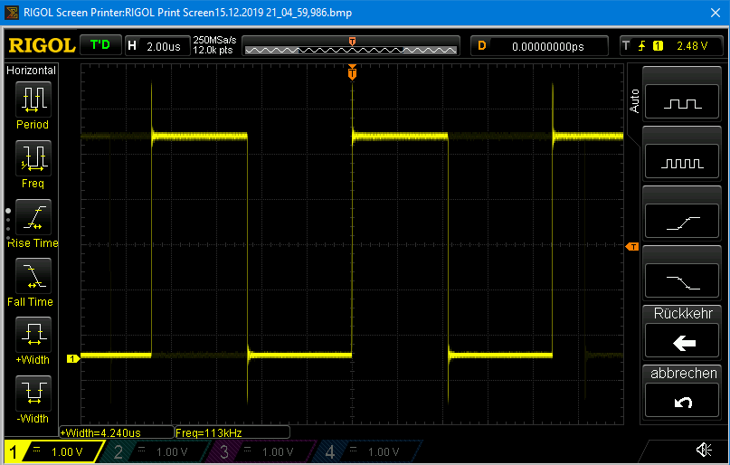
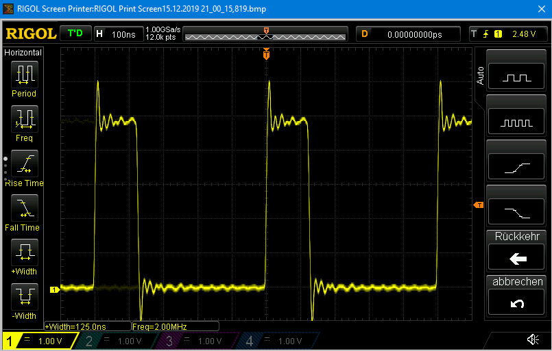
HIGH/LOW cycles, when using digitalWrite, have a maximum frequency of 113 kHz, with port manipulation it is 2 MHz, so a good 17 times faster. 2 MHz means that only 8 processor clocks per cycle are required.
Port manipulation vs. digitalRead
To determine the speed of digitalRead vs. PINx &= (1<<Pin) I used both 100,000 times and determined the time required to do so.
unsigned long numberOfReads = 100000;
unsigned long startTime = 0;
unsigned long readTimeLength = 0;
bool pinStatus;

void setup() {
  Serial.begin(9600);
  pinMode(5,INPUT);
}

void loop() {
  startTime = millis();
  for(unsigned long i=0; i<numberOfReads; i++){
    pinStatus = digitalRead(5);
  }
  readTimeLength = millis() - startTime;
  Serial.print("digitalRead: ");
  Serial.print(readTimeLength);
  Serial.print(" ms ");
  Serial.print(" / ");
  delay(1000);

  startTime = millis();
  for(unsigned long i=0; i<numberOfReads; i++){
    pinStatus = (PIND & (1<<PD5));
  }
  readTimeLength = millis() - startTime;
  Serial.print("PIND Abfrage: ");
  Serial.print(readTimeLength);
  Serial.println(" ms");
  delay(5000);
}
The result:
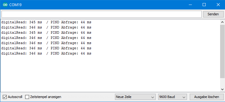
The direct PIND query is therefore a good eight times faster than digitalRead. Division by 100000 shows that the digitalRead function requires about 3.5 µs, while direct querying only takes about 0.44 µs. Of course, this is not exactly the case, as the loop processing itself takes some time. But it shows at least that the difference is significant.
Where does the difference come from?
The reason for difference in speed is that digitalRead and digitalWrite do much more than the simple port manipulation functions. The additional measures that digitalRead and digitalWrite take, make the functions more robust against errors. If you don’t need the speed gain due to port manipulation, then you can still use digitalRead and digitalWrite. As an example here is the definition of the digitalWrite function that you can find in the file Arduino\hardware\arduino\avr\cores\arduino\wiring_digital.c
void digitalWrite(uint8_t pin, uint8_t val)
{
  uint8_t timer = digitalPinToTimer(pin);
  uint8_t bit = digitalPinToBitMask(pin);
  uint8_t port = digitalPinToPort(pin);
  volatile uint8_t *out;

  if (port == NOT_A_PIN) return;

  // If the pin that support PWM output, we need to turn it off
  // before doing a digital write.
  if (timer != NOT_ON_TIMER) turnOffPWM(timer);

  out = portOutputRegister(port);

  uint8_t oldSREG = SREG;
  cli();

  if (val == LOW) {
    *out &= ~bit;
  } else {
    *out |= bit;
  }

  SREG = oldSREG;
}
Acknowledgement
I have taken the Arduino in the post image from Daan Lenaerts on Pixabay. The zeros and ones (which I cut out, colored and inserted as a layer) I owe to Gerd Altmann, also on Pixabay.
Thanks for an excellent article. Just what I was looking for and well paced, good concice examples.
Thank you!
I was lucky enough to find your very illuminating post a long time ago, and implemented some port manipulation successfully in a few sketches. I am mostly using Sparkfun’s Arduino Pro Mini 328. Recently, I added an I2C library to my sketch, and all of a sudden I started to see the compiler error “error: lvalue required as left operand of assignment PORTB |= ((value >> 6) & 0b00000011);”. I assumed I would find some other incompatible library had been #include ‘ed inside that library. All I could see was #include Arduino.h, which I assume is all standard Arduino stuff. Whether that reference is there or commented out, I still get the same compiler error. So, I wondered if I just needed to separate the = and | operators as “PORTB = PORTB | ((value >> 6) & 0b00000011);” but that gave the same result.
Curious to know if there are certain Arduino IDE environment conditions that must be true for port manipulation to work as you have described.
Hi, can you send me the complete sketch to Wolfgang.Ewald@wolles-elektronikkiste.de ? Then I can see if I get the same compiler error and can “play” a little. The Sparkfun Pro Mini 328 is based on an ATmega328, so I have I have no idea why you get this error. Can you also tell me which settings you have selected in the Arduino IDE (Board and Processor)?
Thanks for your interest, I will send it your way. I have the IDE set to board = Arduino Pro or Pro Mini and processor = ATmega328P (5V, 16 MHz). What I find very strange is that I was happily using port manipulation for months, and I had never before seen that compiler error until today. I am using port manipulation on D2-9 and B0-1 on the Arduino. The project has a lot of I2C chips and several MUXs that I am controlling with the IO lines of the MCP2301x. I was using an MCP23017 with the Adafruit library, but I am trying to reorient to the MCP23018 due to supply chain issues. So, I added the MCP23018 library by NorthernWidget Skunkworks (https://github.com/NorthernWidget-Skunkworks/MCP23018) and this problem arose soon after. The new MCP23018 library is working for me to some degree, but not 100%, so I guess I would not rule out the possibility that I have blown something on the Arduino board, but I would not expect that to result in a compiler error.
Replying to my own post to say thanks to Wolfgang for his kind and helpful responses. You are a gem, Wolfgang! To make a long story short, in a library I had added to my sketch, the developer used reserved names like PORTD for variables. That explains why the port manipulation methods Wolfgang describes above started to go haywire after I added that library. Wolfgang could see it more readily than I because he used the verbose compiler setting (facepalm) and there was the answer, plain as day. This demonstrates the value of the verbose compiler setting in a way that I won’t soon forget.
Fantastic tutorial, and exactly what I’ve been looking for. Clear and concise and examples really help to comprehend. Thank you!
Thanks for your kind comment – very motivating!
great tutorial, thanks 🙂
Thanks for the feedback!