About the post
In my last post I have explained the 8 bit timers of the Arduino UNO (or ATmega328P), namely Timer0 and Timer2. In this second part I would like to go into the details of the 16 bit Timer1. Theoretically, it is very similar to the two 8-bit timers, but has greater flexibility and additional functions.
You don’t necessarily have to read part 1, but I’m going to explain fewer details in this part. The following is covered in this post:
- Structure and components of the Timer1
- Normal Mode
- CTC Mode
- PWM Modes
- Fast PWM
- Phase Correct PWM
- Phase and Frequency Correct PWM
- Using the Input Capture Pin
- External clock
Structure and components of the Timer1
The registers of Timer1
Timer/Counter1 Register TCNT1
The Timer/Counter1 Register TCNT1 is 16 bits. The register counts corresponding to the system clock or it can be slowed down with a prescaler. The lower limit is Bottom (zero), the upper limit is Top. Top is fixed or can be defined variably, depending on the mode.
Output Compare Register OCR1x
In the two Output Compare Registers OCR1A and OCR1B you can define values that are permanently compared with the TCNT1 register. Depending on the setting and mode, a match (Compare Match) triggers certain actions. In certain WGM1 modes, OCR1A is Top. The registers are of course 16 bits like TCNT1.
Timer/Counter1 Control Register TCCR1x
The main settings are made in the Timer/Counter1 Control Registers TCCR1A, TCCR1B and TCCR1C. These include:
- Choice of Wave Form Generation Mode via the WGM1 Bits
- Determination of what happens in case of a Compare Match (COM1xy Bits)
- Prescaler or external clock via the Chip Select Bits CS1x


ICES1, the Input Capture Edge Select Bit in TCCR1B, will be discussed together with the Input Capture function. For all other bits please look at the data sheet of the ATmega 48 / 88 / 168 / 328 family.
Input Capture Register ICR1
This Timer1 register has two functions.
- If there is an event on ICP1, the counter reading of TCNT1 is written to ICR1. The ICES1 bit mentioned above determines whether this should happen with the rising (ICES1 = 1) or falling edge (ICES1 = 0).
- Like OCR1A, ICR1 is the Top value in some WGM1 modes. In these cases, the Input Capture Register function is disabled. Unlike OCR1A, ICR1 is not buffered, but is immediately overwritten. We discuss the consequences of this when we get to the PWM modes.
Timer/Counter1 Interrupt Mask Register TIMSK1
In TIMSK1, you enable the interrupts for the Input Capture function (ICIE1), the Output Compare Matches (OCIE1B, OCIE1A), and the Timer Overflow (TOIE1). The “IE” stands for “Interrupt Enable”.

If the respective interrupts are enabled, you can use them in Interrupt Service Routines (ISRs). For this, you pass the corresponding interrupt vectors to the ISR:
- TIMER1_CAPT_vect for Input Capture
- TIMER1_COMPA_vect / TIMER1_COMPB_vect for Compare Match
- TIMER1_OVF_vect for Timer Overflow
Timer/Counter1 Interrupt Flag Register TIFR1
If the interrupts are enabled, the corresponding bits are set in TIFR1 if an interrupt is triggered. Executing an interrupt vector deletes the bit. Alternatively, you delete the bits by overwriting them with 0.

Output Compare Pins OC1x
The Timer1 has two Output Compare pins assigned to it, OC1A (PB1, Arduino UNO Pin 9) and OC1B (PB2, Arduino UNO Pin 10). When I speak of Arduino Pins below, I am referring to the Arduino UNO. Besides, I always refer to digital pins when I’m not writing anything else.

The behavior of the Output Compare pins depends on the setting of the WGM1 bits and the Compare Output bits in TCCR1A and TCCR1B.
Input Capture Pin ICP1
The Input Capture pin corresponds to PB0 (Arduino Pin 8). Thanks to the Input Capture function, the time sequence of fast events can be measured elegantly. I will come back to this towards the end of this article.
External Clock Pin T1
As an alternative to the internal clock, you can attach an external clock to T1 (PD4, Arduino Pin 4).
Settings in TCCR1x
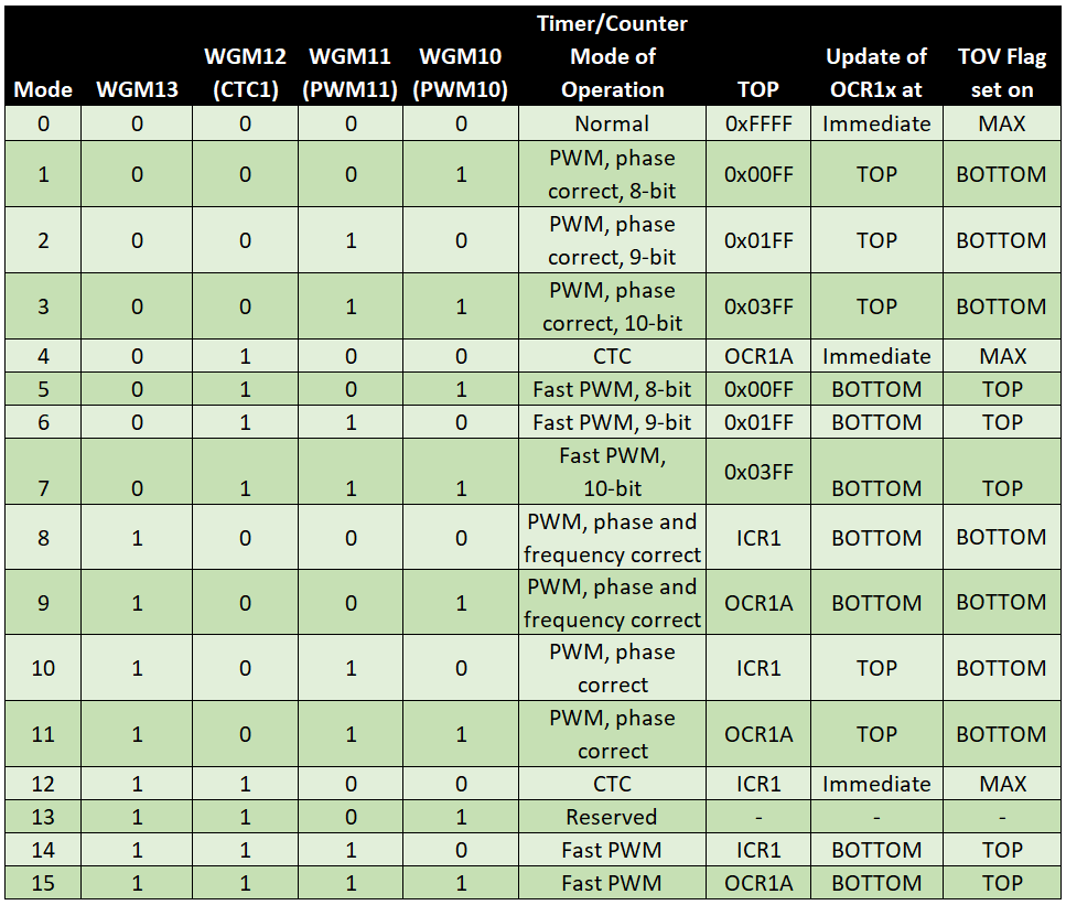
Wave Form Generation Modes
In contrast to the Timer0 and Timer2, four WGM bits are available for the Timer1, i.e. there are 16 different settings. The choice of the WGM is always the basis for all further settings.
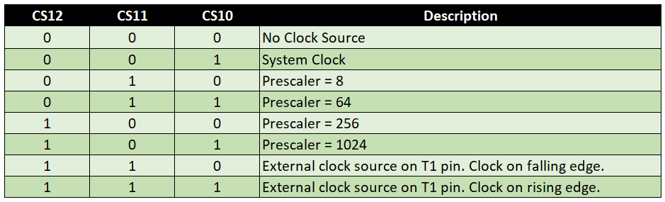
Clock Select Bits / Prescaler
The counting frequency of TCNT1 is determined by the system clock and the prescaler:
![\[ f_{desired}=\frac{system_clock}{prescaler} \]](https://wolles-elektronikkiste.de/wp-content/ql-cache/quicklatex.com-02895c01cb196e405d067622f0303ced_l3.png "Rendered by QuickLaTeX.com")
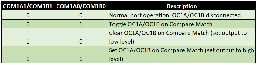
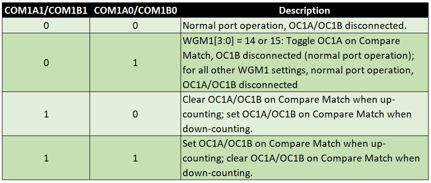
Compare Output Mode Bits
The effect of the COM1xy bits depends on which mode is chosen:

The Normal Mode
In Normal Mode, Top is always 0xFFFF (65535). A complete pass consists of 65536 steps, since the 0 is counted as well. After reaching Top, TNCT1 is set to 0 again. The frequency for the timer overflow is determined by the system clock and the prescaler. In addition, you can provide TCNT1 with a starting value and thus – within the scope of the resolution and the limits – generate arbitrary frequencies for the overflow. However, you must write the starting value again in TCNT1 after each overflow. The frequency fdesired is calculated according to the formula:
![\[ f_{desired}=\frac{system\_clock}{prescaler\cdot (65536-start\_value)} \]](https://wolles-elektronikkiste.de/wp-content/ql-cache/quicklatex.com-b0fa3dcfbd04cb65d9700b0f8ded0452_l3.png "Rendered by QuickLaTeX.com")
![\[ start\_value=65536-\frac{system\_clock}{prescaler\cdot f_{desired}} \]](https://wolles-elektronikkiste.de/wp-content/ql-cache/quicklatex.com-0858f1f541df60086a421430950e80b8_l3.png "Rendered by QuickLaTeX.com")
System clock and frequency are known variables. But still, it’s an equation with two unknowns. I have already discussed this in more detail in Part 1 of the article. That is why I do not want to repeat this here. However, I would like to point out once again the helpful AVR Timer calculators in the net, e.g. here or here.
Normal Mode example sketch
An LED shall turn on and off every second (1s on, 1s off, 0.5 Hz). We do this by overflowing TCNT1 in exactly this frequency and using the Overflow Interrupt to invert the pin to which the LED is connected. With Timer0 and Timer2 we had to introduce an additional scale factor for this application (see last article). Because TCNT1 is 16 bit, this is not necessary here. The Arduino UNO has a clock speed of 16 MHz. This results in two possible combinations: 1) prescaler 256 / start value 3036 or 2) prescaler 1024 / start value 49911. The bits to be set in TCCR1A and TCCR1B are derived from the tables above. TOIE1 must be set to get an overflow interrupt. The LED is attached to PD7 (Arduino Pin 7). In the ISR, the LED pin is inverted and the timer is set back to the starting value.unsigned int counterStart = 3036; // alternative: 49911
void setup(){
TCCR1A = 0x00; // OC2A and OC2B disconnected; Wave Form Generator: Normal Mode
TCCR1B = (1<<CS12); // prescaler = 256; alternative: 1024 (set CS12 and CS10)
TIMSK1 = (1<<TOIE1); // interrupt when TCNT1 is overflowed
TCNT1 = counterStart;
DDRD |= (1<<PD7);
}
void loop() {
// do something else
}
ISR(TIMER1_OVF_vect){
TCNT1 = counterStart;
PORTD ^= (1<<PD7);
}
One advantage of working with timers is that the processes run in the background. The main loop of the sketch is still empty. Normally you would probably have created the flashing LED with a delay construction. It can always be a challenge to build additional code around it, especially if it contains additional time-critical functions. In the last post I had two LEDs flash asynchronously as an example.
CTC Mode
CTC stands for “Clear Timer on Compare Match” and that’s what you do in this mode. Instead of 0xFFFF, Top is either OCR1A (WGM 4) or ICR1 (WGM 12). Top determines the frequency.
Also in CTC mode, counting is only upwards. After peaking, TCNT1 is reset to zero.
CTC Mode Sample Sketch
We do the same as in Normal Mode: an LED shall switch on and off every second (1s on, 1s off, 0.5 Hz). For the calculation of the prescaler and Top: ![\[ f_{desired}=\frac{system\_clock}{prescaler\cdot (1+Top)} \]](https://wolles-elektronikkiste.de/wp-content/ql-cache/quicklatex.com-c754d140633cd866c47aa20eacf624ee_l3.png "Rendered by QuickLaTeX.com")
![\[ Top = \frac{system\_clock}{prescaler\cdot f_{desired}}-1\;\;\;\;mit\;\;\;\;Top < 65536 \]](https://wolles-elektronikkiste.de/wp-content/ql-cache/quicklatex.com-8436d0c0cb18bde1436e7702fe82efbb_l3.png "Rendered by QuickLaTeX.com")
Again, there are two possible combinations for the prescaler and Top. We take the 1024 as prescaler 1024 and 15624 as Top. The alternative would be prescaler 256 and Top 62499. Whether we use Mode 4 or 12 makes no difference, except in the definition of Top. We choose Mode 4, so OCR1A is Top. In the TCCR1A register we set COM1A0. This allows us to define “Toggle OC1A on Compare Match” according to the table. So we do not use the interrupt by means of an ISR, but directly control an Output Compare Pin. And in this case, it is OC1A = PB1 = Arduino Pin 9. OC1A must be set to output because this does not happen automatically. This step should always be done after all other settings.
void setup(){
  TCCR1A = (1<<COM1A0); // Toggle OC1A on Compare Match; Wave Form Generator: CTC Mode 4, Top = OCR1A
  TCCR1B = (1<<WGM12) + (1<<CS12) + (1<<CS10); // prescaler = 1024;
  OCR1A = 15624;
  DDRB |= (1<<PB1);
}

void loop() {
 // do something else
}
Graphically, this looks like this:

Fast PWM
In Fast PWM mode, as well as in all other PWM modes, Top determines the frequency. TCNT1 counts from Bottom to Top and is then reset to zero (one edge per period). In contrast to Timer0 and Timer2 there is an extended selection for Top for Timer1. Depending on the WGM1 bit combination, this is:
- 0x00FF, 0x01FF, 0x03FF – Mode 5 to 7
- ICR1 (Input Capture Register 1) – Mode 14
- OCR1A – Mode 15
Normally, in the PWM modes, you control the Output Compare pins OC1A (PB1, Arduino Pin 9) and OC1B (PB2, Arduino Pin 10) associated with the respective timer. Alternatively, you can also use the Compare Match interrupts.
In the Compare Output Mode table for Fast PWM, you choose the desired behavior of the Output Compare Pins. In the next graphic, OCR1A is chosen as Top. For OCR1B, the option “Clear OC1B at Compare Match, set OC1B at Bottom” was selected. OCR1B therefore determines the duty cycle, OCR1A determines the frequency. In Mode 5 to 7, the frequency is set only by a fixed Top and the prescaler. Accordingly, you cannot choose any desired frequencies in mode 5 to 7.

If you change OCR1A while the program is executed, Top will not be updated until the previous Top has been reached. This delayed update happens because the OCR1x registers are buffered, i.e. there is, so to speak, a clipboard for the values to be updated.
ICR1 does not have a buffer and this has an important consequence. Imagine using ICR1 as your Top and assigning it a new value that is smaller than the current TCNT1 counter reading. In this case, TCNT1 can no longer match Top in the current cycle and counts up to 0xFFFF. And this can take quite a long time depending on the prescaler and counter reading. Therefore, if you want to change the frequency during the program, use OCR1A as the top (Mode 15). Or even better: choose the Phase and Frequency Correct Mode 9.
Fast PWM Sample Sketch
As an example, we generate a 1 kHz signal with 25% DutyCycle at OC1A. ICR1 is intended to serve as Top. First, we have to calculate:
![\[ f_{desired}=\frac{system\_clock}{prescaler\cdot(1+Top)} \]](https://wolles-elektronikkiste.de/wp-content/ql-cache/quicklatex.com-01a9450589a2d54bf0bd426652063342_l3.png "Rendered by QuickLaTeX.com")
![\[ Top=\frac{system\_clock}{prescaler\cdot f_{desired}}-1 \]](https://wolles-elektronikkiste.de/wp-content/ql-cache/quicklatex.com-3be929127dd03946196ade3fc7d68f36_l3.png "Rendered by QuickLaTeX.com")
![\[ Top=\frac{1600000}{1\cdot 1000}-1=15999\;\;\;\;with\;\;\;\;prescaler=1 \]](https://wolles-elektronikkiste.de/wp-content/ql-cache/quicklatex.com-9f5812223463620e4655589fddf06768_l3.png "Rendered by QuickLaTeX.com")
Top is 15999 and that’s 16000 steps. 25% is 4000 steps, which are completed with 3999. We choose the WGM1 bits for Mode 14 because it defines ICR1 as a top. By setting CS10, we select the prescaler 1, i.e. no prescaler. OC1A is PB1 (Arduino Pin 9) and must be set to output.
void setup(){
  // Clear OC1A on Compare Match / Set OC1A at Bottom; Wave Form Generator: Fast PWM 14, Top = ICR1
  TCCR1A = (1<<COM1A1) + (1<<WGM11);
  TCCR1B = (1<<WGM13) + (1<<WGM12) + (1<<CS10); // prescaler = none;
  ICR1 = 15999;
  OCR1A = 3999;
  DDRB |= (1<<PB1);
}

void loop() {
 // do something else
}
The beauty of the fact that the Timer1 allows ICR1 to be TOP is that we have both OCR1A and OCR1B available as a Compare Match for controlling the output pins. We extend the sketch with a signal to OC1B with 75% Duty Cycle:
void setup(){
  // Clear OC1A and OC1B on Compare Match / Set OC1A and OC1B at Bottom;
  // Wave Form Generator: Fast PWM 14, Top = ICR1
  TCCR1A = (1<<COM1A1) + (1<<COM1B1) + (1<<WGM11);
  TCCR1B = (1<<WGM13) + (1<<WGM12) + (1<<CS10); // prescaler = 1 (none)
  ICR1 = 15999;
  OCR1A = 3999;
  OCR1B = 11999;
  DDRB |= (1<<PB1)|(1<<PB2);
}

void loop() {
 // do something else
}
This is what it looks like on the oscilloscope:

As an exercise, you can slow down the settings so that you can make the PWM signal visible on two LEDs. If you don’t have an oscilloscope, it’s more satisfying. As in the last article, however, I would like to refer once again to the DSO 138, an oscilloscope for less than 30 euros. As a start, I highly recommend this. At Amazon, ebay and Co it’s available in many shops.
Using Fast PWM
The name already suggests that Fast PWM is fast. Therefore, this mode is mainly used where this property is important. You will learn soon why it is twice as fast as the other PWM modes. The limitations of Fast PWM compared to the other PWM modes are more understandable, if you look at them in comparison.
Phase-Correct PWM
In the Phase-Correct PWM, TCNT1 counts up from Bottom to Top and then down again (two flanks per period). Top values are again
- 0x00FF, 0x01FF, 0x03FF – Mode 1 to 3
- ICR1 – Mode 10
- or OCR1A – Mode 11
to choose from. In the following I would like to explain the special features of this mode using a concrete example. OCR1A is defined as Top and OCR1B as Compare Match:

The period doubles compared to Fast PWM, or the frequency halves. A Compare Match with OCR1B takes place both when counting up and down.
Since you should be able to make the settings yourself, and because the article should not be longer, I have omitted further example sketches.
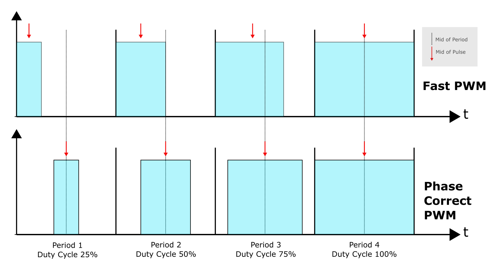
Phase-Correct PWM at constant frequency
OCR1A and OCR1B are updated when TCNT1 reaches Top. This ensures that the center of the pulse is always in the middle of the period, as long as only OCR1B is varied. In Fast PWM, the center of the pulse wanders through the period as the pulse width changes. Sounds complex, but it is not:
A nice animation can be found here.
A typical application for Phase-Correct PWM is the control of servo motors, as they like a symmetrical signal. I will perhaps write something about servo motors separately.
Phase-Correct PWM at varying frequency
If the Top changes, i.e. a frequency change, we still have the update problem when using ICR1 as the top. If ICR1 is updated as a Top while you’re counting and it is less than the current TCNT1 value, there will be no “Top Match” in the current cycle.
With OCR1A as Top, there is another problem if you change this value in the running program. Imagine you’re updating Top while TCNT1 is counting down. The length of the falling edge is then still determined by the old TOP. The length of the rising edge, on the other hand, is determined by the new Top. Again, this makes the signal asymmetrical. You can prevent this by switching to Phase and Frequency Correct PWM mode.
Phase and Frequency Correct PWM
Also in the phase and frequency correct PWM, TCNT1 counts from Bottom to Top and then down to Bottom. The same scheme applies as for the phase-correct PWM (Graph 3). The difference is that OCR1A and OCR1B are updated at Bottom. This ensures that there are always two symmetrical edges. You find more graphics related to this In the data sheet of the ATmega 48 / 88 / 168 / 328 family.
Summary: which PWM mode is appropriate?
- Fast PWM: with constant frequency and pulse width or applications that are not allergic to the migration of the pulse center associated with the pulse width change
- Phase Correct PWM: with variation of pulse width and constant frequency
- Phase and Frequency Correct PWM: with variation of frequency
Help for the Timer and PWM programming
Timer and PWM programming can be quite annoying and confusing. A great help is the tool “Arduino Web Timers” from David Buezas, that you find here. I really highly recommend it.
Using the Input Capture Pin
As promised above, I would like to return to the Input Capture function. It would be a pity to reduce it simply to having another TOP available with ICR1.
The Input Capture Pin allows you to measure events conveniently in the background in terms of their chronological sequence. The following example illustrates the principle. It’s not very nicely programmed with its many global variables, but that’s not what matters here.
I have a push button attached to ICP1 (PB0, Arduino Pin8). Pressed it is HIGH, otherwise LOW. After pressing ten times, the time at which the button was pressed is output.
Using the Timer1 in Normal Mode, the sketch registers the seconds. For this, I have chosen the prescaler 256 and the starting value 3036. The frequency is 1 Hz and 1 second corresponds to 62500 steps. For each timer overflow, the seconds are incremented. By setting ICES1, the rising edge of the signal on ICP1 is selected. ICIE1 and TOIE1 enable the required interrupts.
When pressing a button, the TCNT1 counter reading is stored in ICR1. Subtracting the start value and dividing by 62.5 provides the milliseconds. The push-button presses are stored in an array.
unsigned int counterStart = 3036;
unsigned int eventTime[10][2];
volatile unsigned int seconds = 0;
unsigned int ms = 0;
unsigned int eventCounter = 0;
volatile bool event = false;
const float ms_const = 62.5;

void setup(){
  Serial.begin(9600);
  TCCR1A = 0; // Normal Mode
  TCCR1B = (1<<ICES1) + (1<<CS12);
  TIMSK1 = (1<<ICIE1) + (1<<TOIE1);
  TCNT1 = counterStart;
}

void loop() {
  if(event){
    eventTime[eventCounter][1] = seconds;
    eventTime[eventCounter][2] = round((ICR1 - 3036) / ms_const);
    eventCounter++;
    if(eventCounter==10){
      ausgabeZeiten();
      eventCounter=0;
    }
    event=false;
  }
}

void ausgabeZeiten(){
  Serial.println("Tastendruck nach: ");
  for(int i=0; i<10; i++){
    Serial.print(i);
    Serial.print(": ");
    Serial.print(eventTime[i][1]);
    Serial.print(" Sekunden, ");
    Serial.print(eventTime[i][2]);
    Serial.println(" Millisekunden");
  }
}

ISR(TIMER1_OVF_vect){
  TCNT1 = counterStart;
  seconds++;
}

ISR(TIMER1_CAPT_vect){
  event = true;
}
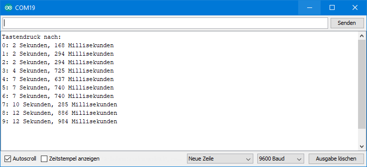
Output of the Input Capture example sketch
I pressed the button every 2-3 seconds. In the output you can see the push-button bounce. Of course, this example could have been easily programmed with a digitalRead / millis combination. The beauty of the Input Capture method, however, is that you don’t have to query the time of the event immediately. It is stored safely in ICR1. In addition, the time of the event can be determined in very high resolution, namely precisely to the system clock.
External clocks on T1
As can be seen from the Clock Select Bit table, you can attach an external clock to T1 (PD5, Arduino Pin 5). You have the choice whether the rising or falling edge serves as the clock signal. In part 1 of this article I had attached a push button to T0 as a clock and I switched an LED with it. I was all the more astonished that it didn’t work with T1 on the Arduino. The following sketch was used:
// geht nicht!!!!
void setup(){
  TCCR1A |= (1<<COM1A0) + (1<<WGM11) + (1<<WGM10);
  TCCR1B |= (1<<WGM13) + (1<<WGM12) + (1<<CS12) + (1<<CS11) + (1<<CS10);
  OCR1A = 10;
  DDRB |= (1<<PB1);
}

void loop() {
 // do something else
}
Actually, the LED and OC1A (PB1, Arduino Pin9) should turn on or off with every tenth press of the push button. I do not know why this is not happening. Does anyone have an idea? But it seems to be due to the setup of the Arduino, because the same sketch, translated into C, worked with Atmel Studio on the “naked” ATmega328P without any problems:
#include <avr/io.h>
#include <util/delay.h>

int main(void)
{
    TCCR1A |= (1<<COM1A0) + (1<<WGM11) + (1<<WGM10);
    TCCR1B |= (1<<WGM13) + (1<<WGM12) + (1<<CS12) + (1<<CS11) + (1<<CS10);
    OCR1A = 10;
    DDRB |= (1<<PB1);

    while (1)
    {
    }
}
Acknowledgement
I owe the hourglass in the post image “derGestalterCottbus” on Pixabay.
Hi,
Thanks for article. I’ve got problem with my Arduino code too. I was trying to get PWM signal on pin OC1A. It worked but after some code modifications it stopped working. You wrote that same code work in Atmel Studio but not in Arduino. It was quite uplifting for me, I thought that there is something wrong with my code :).
Ok, the problem in my case was that PWM worked until I used ‘digitalRead’ function to read OC1A pin in ‘loop’ function. After using ‘digitalRead’, OC1A pin stays in LOW state. In source code of digitalRead function I found:
// If the pin that support PWM output, we need to turn it off
// before getting a digital reading.
if (timer != NOT_ON_TIMER) turnOffPWM(timer);
It looks like reading pin disables PWM.
So I read pin just by
pwmout= PINB & _BV(PWM_OUT)
and It’s OK now.
Best Regards.
Hi Rafal,
yes, digitalRead and digitalWrite do much more than one would expect. The aim of the Arduino API is to make microcontrollers easy to use and to avoid unwanted side effects when using the Arduino functions. But when mix Arduino functions with code that directly addresses registers, then things can be messed up. I should highlight this in the article. So, thanks for your comment!
Best regards, Wolfgang
Hi,
Thanks for a great article, it helped me a lot to understand arduino timers. Sadly I am still a bit lost in higher frequencies (I am looking into ideally 10kHz frequency (can be ~8kHz) PWM with a duty cycle controllable from external input)
In sketch T1_FastPWM_Mode14_DutyCycle25.ino
I found out that I can control duty cycle by controlling ICR1, OCR1A and OCR1B from external interrupts.
The only thing I can’t find out is how to increase frequency to 10kHz ideally, or at least to ~8kHz.
Prescaler is already set to 1, so I can’t go lower.
If you could help me with that I’d appreciate a lot.
Thanks in advance.
Hi Joe, you need to change f_desired in the equations from 1000 Hz to 8000 Hz as an example. Then ICR1 is 1999 and for a Duty Cycle of 25% OCR1A should be 499. Can you try?
Thank you very much. Yes, it works perfectly. Understood it finally :):
————————————————————–
// Fast PWM 8kHz at Arduino digital pin 9 sample
void setup(){
// Clear OC1A on Compare Match / Set OC1A at Bottom; Wave Form Generator: Fast PWM 14, Top = ICR1
TCCR1A = (1<<COM1A1) + (1<<WGM11);
TCCR1B = (1<<WGM13) + (1<<WGM12) + (1<<CS10); // prescaler = none;
ICR1 = 1999;
//OCR1A = 8; // duty cycle ~1%
OCR1A = 499; // duty cycle 25%
//OCR1A = 1499; // duty cycle 75%
//OCR1A = 1990; // duty cycle ~99%
DDRB |= (1<<PB1);
}
void loop() {
// do something else
}
————————————————————–
P.S. is it safe to say that
OCR1A = 0;
means output on the selected pin is off?
10kHz fast PWM
————————————————————–
// Fast PWM, 10kHz at Arduino digital pin 9 sample
void setup(){
// Clear OC1A on Compare Match / Set OC1A at Bottom; Wave Form Generator: Fast PWM 14, Top = ICR1
TCCR1A = (1<<COM1A1) + (1<<WGM11);
TCCR1B = (1<<WGM13) + (1<<WGM12) + (1<<CS10); // prescaler = none;
ICR1 = 1599;
//OCR1A = 8; // duty cycle ~1%
OCR1A = 399; // duty cycle 25%
//OCR1A = 1199; // duty cycle 75%
OCR1A = 1590; // duty cycle ~99%
DDRB |= (1<<PB1);
}
void loop() {
// do something else
}
————————————————————–
Hello again Sir,
I finished writing my code long time ago and i was working with a baud rate of 9600 back then. Right now i am trying to add this piece of code to another project which is supposed to work at a baud rate of 115200. When the frequency generator code is working at 9600 BR there is no problem but when i increase the baudrate anything higher than 9600 (115200 as an example), it starts to behave abnormal (It skips the wait for frequency input ). Maybe this is not a question i should be asking you but i wanted try my chance and i would be happy if you could take a look. Is it something to do with the registers.
Here is my code:
void setup()
{
Serial.begin(9600);
Serial.println();
//TCCR1A = (1<<COM1A1) + (1<<WGM11) + (1<<WGM10);
TCCR1A = (1<<COM1A1) + (1<<WGM11);
//TCCR1B = (1<<WGM13) + (1<<WGM12) + (1<1010 1.98khz -> 1.98khz / ICRA 10000->10010 201hz -> 200 hz Not good for lower than 100 i guess
TCCR1B = (1<<WGM13) + (1<<WGM12) + (1<<CS11) + (1<<CS10); // Fast PWM with ICRA Top & prescaler value = 64
//TCCR1B = (1<<WGM13) + (1<<WGM12) + (1<<CS12); // Fast PWM with ICRA Top & prescaler value = 256
//TCCR1B = (1<<WGM13) + (1<<WGM12) + (1<<CS12) + (1<<CS10); // Fast PWM with ICRA Top & prescaler value = 1024
ICR1 = 5000; // Frequency
DDRB |= (1<<PB1); //Output Pin (PB1/OCR1A/PIN9 & PB2/OCR1B/PIN10)
delay(100);
Serial.println("Please Enter the desired frequency of the chopper");
while(Serial.available()==0){};
long frequency = Serial.parseInt();
Set_frequency(frequency);
Serial.print("Chopper Frequency Set to: ");
Serial.print(frequency );
Serial.println("Hz");
}
void loop()
{ }
//FREQUENCY GENERATOR SET FUNCTION
long Set_frequency(long frequency_to_set)
{
long prescaler = 64;
long denom = prescaler * frequency_to_set;
long systemClock = 16000000;
ICR1 = ((systemClock/denom)-1);
OCR1A = ICR1 / 2; // fixed %50 duty cycle
frequency_to_set = (systemClock/(prescaler*(1+ ICR1)));
return frequency_to_set;
}
Interesting! Maybe a short delay after:
Serial.println(“Please Enter the desired frequency of the chopper”);
could help?
Dear Wolfgang Ewald,
This answeer helped me a lot. A short delay was not enough unfortunately but it was the first step of the solution ! I added a large delay and one additional if statement and this solved the problem. Here is the part i changed.
delay(10000);
while (Serial.available() == 0) {
if (Serial.read() > 0)
break;
};
Thank you very much for your time again, you are the best !
Regards
Dear Wolfgang Ewald,
This is such a great article, I have learned so much ! Thank you very much for your time and efforts. I am currently working on a frequency generator and this article helped me a lot, I was able to implement a dynamic frequency generating code with mode 14 however I am having problems with mode 15. What should be the setup look like for us to work with mode 15 ?
Here is my set-up code:
TCCR1A = (1<<COM1B1) + (1<<WGM11) + (1<<WGM10); //Clear OC1B at Compare Match, set OC1B at Bottom
TCCR1B = (1<<WGM13) + (1<<WGM12) + (1<<CS12); //Prescaler 256
OCR1A = 4000; // Frequency
OCR1B = 2000; // Duty Cycle 50p
DDRB |= (1<<PB1); //Output Pin (PB1/OCR1A/PIN9 & PB2/OCR1B/PIN10)
I am not able to obtain any kind of PWM signal by using this code. Could you please help me?
Thank you very much in advance
Best Regads
Dear Wizard of Oz,
you have chosen a signal at OC1B = PB2 = PIN10. But you put PB1 to OUTPUT which is OC1A=PIN9. Just change
DDRB |= (1<<PB1);
to
DDRB |= (1<<PB2);
and you will get a PWM signal with a frequency of ~15.6 Hz at OC1B = PB2 = PIN10 !
So, you were almost there, already.
Best wishes, Wolfgang
Dear Wolfgang Ewald,
Thank you very much for your extremely quick response. With the help of your answer, I was able to detect other errors in other codes of mine, and now they all work just fine.
Thank you very much for your efforts and time
Best Regards
Dear Wolfgang Ewald,
Here I am with one more question. Would it be possible for me to use pin 10 for the SPI connection while I am generating a PWM signal using mode 14 (receiving a signal from pin 9)?
Best Regards
Hi, I don’t know why that shouldn’t work. The example sketch T1_FastPWM_Mode14_DutyCycle25.ino provides the PWM signal at pin 9 and uses mode 14.
Regards, Wolfgang
This is great lecture, Thanks a lot. I am new to arduino and not much knowledge about timers. This was very helpful.
I am planning to make a project which needs variable frequency PWM output. As I understand here I must use Phase and Frequency Correct PWM mode. I need 8 to 24 Khz frequency and %8-%12 cycle. How can I do it? Your hint will be appreciated.
Have a good day.
Hi, I had to read my own article again to get back into the topic! So, yes if you want to vary the frequency you should choose one of the Phase and frequency correct modes, e.g. mode 8. The frequencies you want to set are quite fast, so you don’t need a prescaler. I assume your system clock is 16 MHz. To get your PWM at OC1A (=PB1 = digital pin 9) you set:
TCCR1A = (1<<COM1A1);
TCCR1B = (1<<WGM13) + (1<<CS10);
DDRB |= (1<<PB1);
In mode 8, Top is ICR1. If your ICR1 is 999 your frequency is 8 kHz. You can calculate this with the equations in the article, but keep in mind that the frequency in phase correct modes are 50% compared to the other modes. If you want to achieve a frequency of 24 kHz ICR1 would be ~333. The duty cyle (dc) is determined by the ratio of OCR1A and ICR1:
ICR1 = dc * OCR1A / 100
E.g. at frequency of 8 KHz, OCR1A would be 99 to achieve a duty cycle of 10%.
Hope this helps – good luck with your project!
Best wishes.
You are so kind and I aprreciate,Thank you very very much.
You replied me very fast, and thank you again one more time.
Best wishes
Thanks for this
It was helpful.
Thanks for the feedback!
Hi
How about quadrature output ?
Hi, you mean something like this?
https://deltamotion.com/support/webhelp/rmctools/Controller_Features/Transducer_Basics/Quadrature_Fundamentals.htm#:~:text=Quadrature%20encoders%20use%20two%20output,rotating%20in%20a%20clockwise%20direction.
Honestly speaking I have to learn a bit about this topic myself before I can give a competent answer.
External clocks on T1 – “Toggle on OCA1 on compare match” at Fast PWM Modes does not work. The others does.
Do you use an Arduino? In chapter “External clocks on T1” I have described that it doesn’t work on an Arduino.
Yes, I use Arduino. I mean that External clocks work in other Fast PWM Modes – 1, 3 and 4, except of second where COM1A1/COM1B1 = 0, COM1A0/COM1B0 = 1.
Thank you for this article and part 1 of course. They are very helpfil.
OK, I see. Thanks for the clarification and for this hint.