About this post
In this article about timer and pulse width modulation (PWM) I will dive into the depths of the Arduino UNO and the ATmega328P respectively. The Arduino is a great invention that makes it easy to enter the world of microcontrollers. However, the price of simplification is that not all capabilities of the underlying microcontroller have been transferred to the Arduino world. Timer and PWM are definitely part of this. These features are still accessible (with few limitations), but only through the somewhat cryptic logic (bit) operations.
I will try to explain the subject in a comprehensible way with many small examples. As a result, the post has become extremely long – more of a book chapter than a blog post. But I also want that more inexperienced “Arduinoists” understand it. However, to understand this article, you will need some knowledge of logic operations and port manipulation. If you still have some catching up to do, look at my last post.
Because of the size, I limit myself to the 8 bit timers in this article. I deal with the 16 bit timer in part 2.
Content
So, that’s what I will talk about:
- What are timers and PWM
- Which timer does the Arduino UNO (or ATmega 328 P) have?
- The four timer modes:
- Normal
- CTC (clear timer on compare match)
- Fast PWM
- Phase-correct PWM
- C – sketches in Atmel Studio
What is a timer, what is PWM?
I start quite simply: first, a counter belongs to a timer. And it does what you would expect – namely it counts. It counts repeatedly up or down to a limit or up to adjustable limits. The counter becomes a timer when it counts time-dependently. Finally, the timer does not make sense until reaching the limit or an intermediate value can trigger an event.
PWM is simply the technique of periodically switching the digital outputs of your microcontroller HIGH and LOW, i.e. generating square wave signals with certain patterns. And since this is supposed to happen rapidly and in the background, you use timers for it. You have certainly already generated PWM signals, e.g. via analogWrite, servo motor control or the tone function. This is ready-made food, so to speak. Here you will learn how to “cook” PWM signals yourself.
The timers of the Arduino UNO
In this post (and part 2), I’ll cover the following timers:
- Timer0: 8 bit
- Timer1: 16 bit (part 2)
- Timer2: 8 bits
The corresponding counters, control registers and I/O pins
The Timer/Counter Register TCNTx
Now it’s getting dry and theoretical. But don’t worry, the examples will make things clearer. Learn now – and understand later.
Depending on their size, there are one or two counter registers for each timer, namely TCNT0 (Timer/Counter 0), TCNT1L, TCNT1H and TCNT2. Since the Timer1 is 16 bit, it needs two registers. In the following, however, I limit myself to the two 8 bit timers.
The Timer/Counter Control Registers TCCRxy
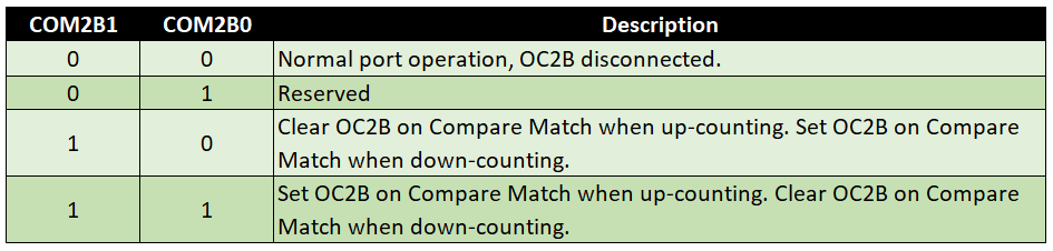
The main settings for the timers are made in the Timer/Counter Control Registers. TCCR0A and TCCR0B belong to Timer0, TCCR2A and TCCR2B belong to Timer2. Here is an example of the Timer2 Control Registers:


You can also find the registers and their description in the rather elongated data sheet for the ATmega 48 / 88 / 168 / 328 family.
The designations for the registers and bits are defined in the AVR libraries by #define instructions. And since these libraries are an integral part of the Arduino IDE, this makes access easy.
Basically, the bits of the register are like switches: set bit = 1 = switch on, bit not set = 0 = switch off. How to combine the switches in a meaningful way is the subject of this article.
The Timer/Counter Interrupt Mask Registers TIMSKx
If you want a timer/counter overflow or the match with a comparison value (Compare Match) to trigger an interrupt, you can set this in the corresponding registers TIMSK0 or TIMSK2. Here TIMSK2 as an example:

Setting TOIE2 (Timer/Counter2 Overflow Interrupt Enable) causes a register overflow of TCNT2 (at 8 bits that’s after 255) to trigger an interrupt. Setting OCIE2A and OCIE2B bits (= Timer/Counter2 Output Compare Match Interrupt Enable A or B) cause an interrupt to be triggered if TCNT2 matches the comparison values in the Output Compare Registers.
TIMSK0 is organized accordingly. Simply replace 2 with 0 each.The Output Compare Register OCRxy
For Timer0 and the Timer2 there are the Output Compare Registers OCR0A and OCR0B respectively OCR2A and OCR2B. When you use them, the content in TCNT0 or TCNT2 is constantly compared with the OCR0A/OCR0B or OCR2A/OCR2B register values. What happens in case of a match is specified in the Timer/Counter Control Registers (TCCRxy).
The Output Compare Pins OCxy
The timers/counters each have two pins assigned, OCxA and OCxB. In the Timer/Counter Control Registers (TCCRxy) you specify the status of the pins for a compare match or timer overflow.
The following diagram shows where these pins are located on the ATmega328P and which are the corresponding Arduino pins.

Overview of the settings
Hold out – I have to torment you a little with more information until we get to the examples.
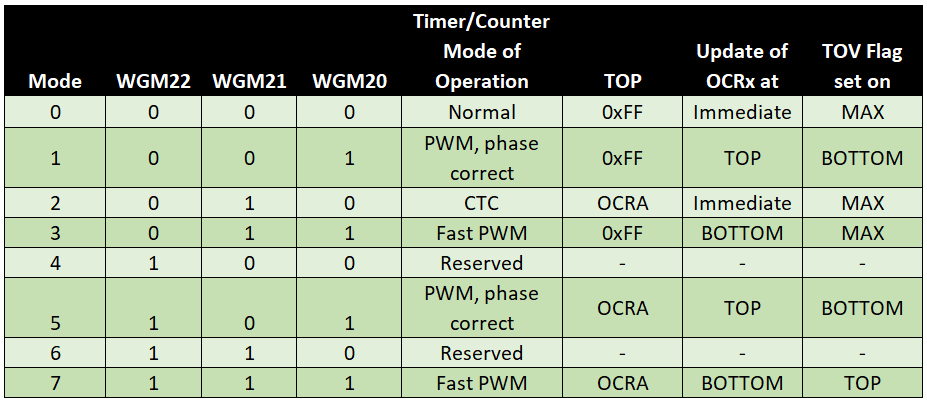
First, you set the Wave Form Generation Mode in the Timer/Counter Control Registers (TCCRxy). The three bits WGMx0, WGMx1 and WGMx2 are responsible for this. Why they had to spread these bits into two registers is a mystery to me. Here is an overview for the Timer2:
The Output Compare Modes
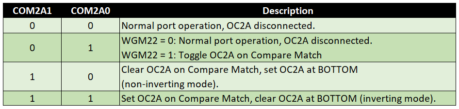
The Compare Output Mode, i.e. the effect of the bits COMxyz (with x = 0 or 2, y = A or B, z = 0 or 1) depends on the selected WGM mode.


These were the settings for Timer2. The good news: all previous tables of the Timer2 correspond to those of the Timer0. You only have to replace 2 with a 0 where 2 represents the timer.
Prescaler settings
The speed at which the Timer/Counter register TCNTx counts is based on the system clock. At the Arduino UNO, that’s 16 MHz. For many applications, this is far too fast. Therefore, there is the prescaler, which causes the counter to be incremented only every nth clock. You can make the settings for this in the Timer/Counter Control Register B (TCCRxB) with the Clock Select Bits (CSx0, CSx1,CSx2). For the Timer2:

For the Timer0 the table is different, more about this later. There is a reason why I start with the Timer2. More about that later, too.
The timer in normal mode
Done, now it’s time to put it in practice. So complex the settings, so simple the sketches. The confusion will disappear.
We start with normal mode. This is suitable for rather slow applications.
The first sketch in Normal Mode
For the following sketch, you connect an LED to the Arduino Pin 7 (PD7). You set the control register A of the Timer2, i.e. TCCR2A, to 0. This deactivates the OC2A pin. All CS2x bits are set in Timer/Counter Control Register B (TCCR2B). The prescaler is therefore 1024. No WGM2x bit is set, so Normal Mode is active. In the Timer/Counter2 Interrupt Mask Register, the bit for the Timer Overflow Interrupt is set. This means that every time the TCNT2 overflows ( > 255), an interrupt is triggered. What you do with the interrupt is defined in the ISR (Interrupt Service Routine). The ISR handles TIMER2_OVF_vect, i.e. the Timer2 Overflow Interrupt. A table of available interrupts can be found in the data sheet.
In this case, the interrupt causes the pin 7 to be inverted. Note: with DDRD |= (1<<PD7) pin 7 was defined as output. This setting should always be made after the other register settings.
void setup(){
  TCCR2A = 0x00; // Wave Form Generation Mode 0: Normal Mode; OC2A disconnected
  TCCR2B = (1<<CS22) + (1<<CS21) + (1<<CS20); // prescaler = 1024
  TIMSK2 = (1<<TOIE2); // interrupt when TCNT2 is overflowed
  DDRD |= (1<<PD7);  // Portmanipulation: replaces pinMode(7, OUTPUT);
}

void loop() {
 // do something else
}

ISR(TIMER2_OVF_vect){
    PORTD ^= (1<<PD7); // toggle PD7
}
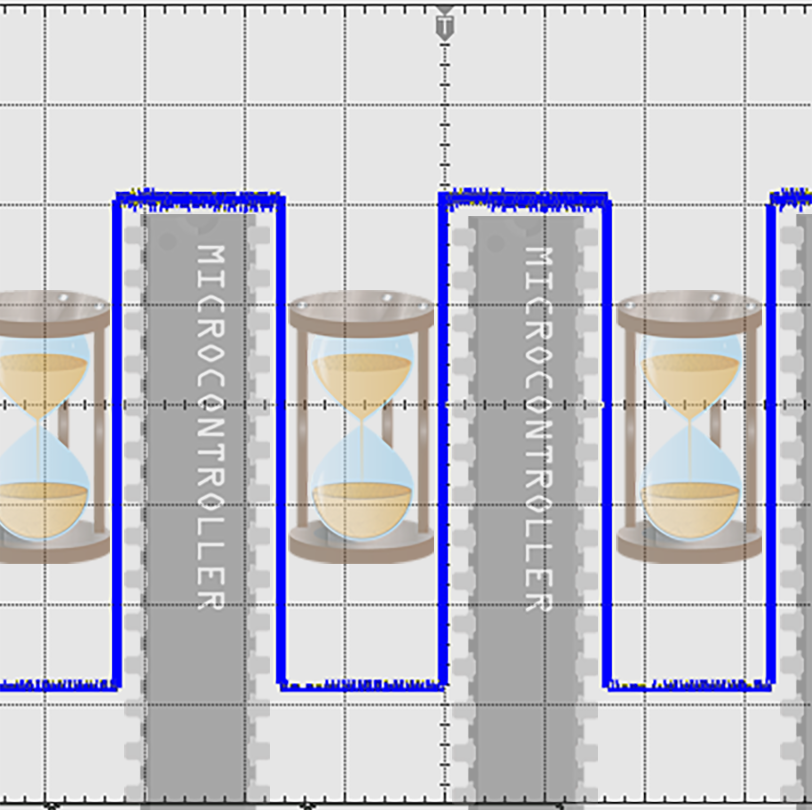
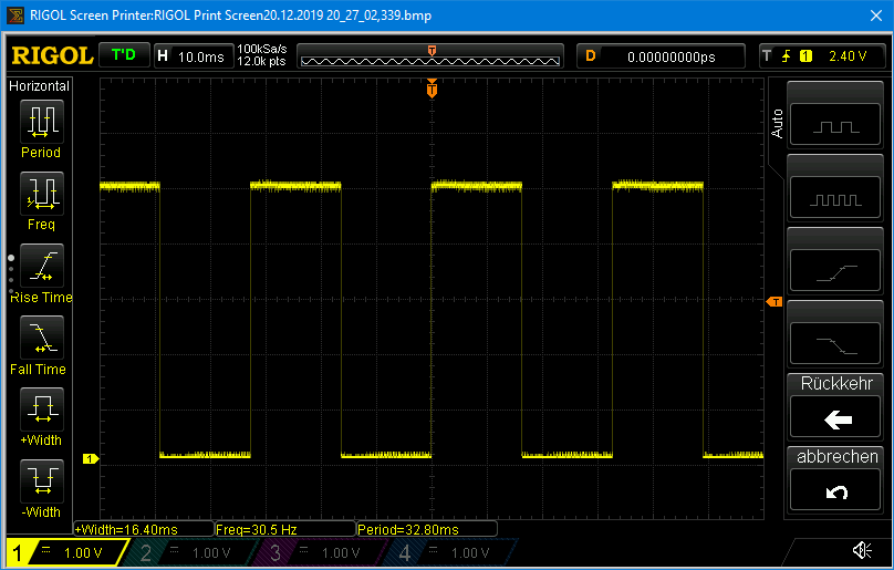
Upload the sketch and see what happens. This is the result on the oscilloscope:
If you transfer the sketch to the Timer0, you will receive an error message:

The problem is that in the Arduino environment the Timer0_OVF_vect is used for other things. That’s why I started with the Timer2. In other environments, such as Atmel Studio, the problem does not exist. At the end of the article, I will come back to that.
Calculation of the frequency
You can see that the LED flashes very fast when using the last sketch. The Arduino clocks 16 million times per second. Due to the prescaler setting, TCNT2 is increased every 1024th clock. TCNT2 starts at 0 and overflows after 255. That’s 256 steps (like a for(i = 0; i<256; i++)). Therefore, the general formula for frequency f is:
![\[ f=\frac{system\_clock}{prescaler\cdot256}=\frac{16000000}{1024\cdot 256}=61.035...[\text{s}^{-1}] \]](https://wolles-elektronikkiste.de/wp-content/ql-cache/quicklatex.com-78ecf46970cc958a429332cc0b56e9ef_l3.png "Rendered by QuickLaTeX.com")
TCNT starts at Bottom (here: 0) and counts to Top. In the WGM table you find for Normal Mode: Top = 0xFF and TOV flag set on MAX (=TOP). PD7 inverts with each overflow.
Further downgrade of the frequency
So even with the maximum prescaler, the frequency for a blinksketch is still very high. To further slow down the process, we introduce a scale factor into the ISR (counter = 60). This results in a frequency of about 1. Strictly speaking, 61,035… / 60 [s-1].
void setup(){
  TCCR2A = 0x00; // Wave Form Generation Mode 0: Normal Mode, OC2A disconnected
  TCCR2B = (1<<CS22) + (1<<CS21) + (1<<CS20); // prescaler = 1024
  TIMSK2 = (1<<TOIE2); // interrupt when TCNT2 is overflowed
  DDRD |= (1<<PD7);
}

void loop() {
 // do something else
}

ISR(TIMER2_OVF_vect){  // Interrupt Service Routine
  static int counter = 0;
  counter++;
  if(counter==60){
    PORTD ^= (1<<PD7);
    counter = 0;
  }
}
Setting an exact frequency
In the next step, we want to set a frequency of exactly 1 Hz. For this, we use the option to define a starting value for the TCNTx register. Then it’s only 256 - starting_value steps to the overflow. The general formula is:
![\[ f_{desired}\cdot scalefactor = \frac{system\_clock}{prescaler\cdot(256-start\_value)} \]](https://wolles-elektronikkiste.de/wp-content/ql-cache/quicklatex.com-cc7614e4ed3755f20a39d8411bb619bc_l3.png "Rendered by QuickLaTeX.com")
With fdesired = 1 results:
![\[ start\_value=256-\frac{system\_clock}{prescaler\cdot scalefactor} \]](https://wolles-elektronikkiste.de/wp-content/ql-cache/quicklatex.com-e5825d49e477c2c289edc45269045bf6_l3.png "Rendered by QuickLaTeX.com")
The system clock is 16 MHz. But it’s still an equation with three unknowns. However, we know that the prescaler can take only certain values, that the starting value must be less than 256 and it must be an integral number. So let’s try a bit:
![\[ start\_value = 256-\frac{15625}{scalefactor}\;\;\;\;\;with\;prescaler=1024 \]](https://wolles-elektronikkiste.de/wp-content/ql-cache/quicklatex.com-746f0ca8c7ef65202b106c43c0d46d5e_l3.png "Rendered by QuickLaTeX.com")
![\[ start\_value = 256-\frac{62500}{scalefactor}\;\;\;\;\;with\;prescaler=256 \]](https://wolles-elektronikkiste.de/wp-content/ql-cache/quicklatex.com-bbb3d62caee875979df9c5df6b15bbd8_l3.png "Rendered by QuickLaTeX.com")
![\[ start\_value = 256-\frac{250000}{scalefactor}\;\;\;\;\;with\;prescaler=64 \]](https://wolles-elektronikkiste.de/wp-content/ql-cache/quicklatex.com-aa154f422e651997f95383018c1a096c_l3.png "Rendered by QuickLaTeX.com")
The prescaler 1024 delivers “crooked” values. With a prescaler of 256, it looks better. If we take a scale factor of 500, we get a starting value of 131. With a prescaler of 64 and a scale factor of 1000, a starting value of 6 results. Both are good.
If you don’t want to calculate, then you can use calculators, which you find e.g. here or here. Although these calculators do not consider scale factors, they are still a help.
The previous sketch is slightly changed. TCNT2 must be set back to the start value at the beginning and after each overflow.
byte counterStart = 131;  // alternative: 6
unsigned int scaleFactor = 500; // alternative: 1000

void setup(){
  TCCR2A = 0x00; // OC2A and OC2B disconnected; Wave Form Generation Mode 0: Normal Mode
  TCCR2B = (1<<CS22) + (1<<CS21); // prescaler = 256
  // TCCR2B = (1<<CS22); // prescaler = 64;
  TIMSK2 = (1<<TOIE2); // interrupt when TCNT2 is overflowed
  TCNT2 = counterStart;
  DDRD |= (1<<PD7);
}

void loop() {
 // do something else
}

ISR(TIMER2_OVF_vect){
  static int counter = 0;
  TCNT2 = counterStart;
  counter++;
  if(counter==scaleFactor){
    PORTD ^= (1<<PD7);
    counter = 0;
  }
}
An application in normal mode: asynchronous LEDs
You may have noticed that the main loop was empty in the previous sketches. The control of the flashing LED happens in the background. If the blink code was part of the main loop, then all additional code has to be programmed “around” that. This can become quite challenging, if other time-dependent tasks shall take place in parallel.
As a simple example, we let two LEDs flash asynchronously in the next sketch. Try programming this without a timer.
byte counterStart = 131;  // alternative: 6
unsigned int scaleFactor = 500; // alternative: 1000

void setup(){
  TCCR2A = 0x00; // OC2A and OC2B disconnected; Wave Form Generator: Normal Mode
  TCCR2B = (1<<CS22) + (1<<CS21); // prescaler = 256
  // TCCR2B = (1<<CS22); // prescaler = 64;
  TIMSK2 = (1<<TOIE2); // interrupt when TCNT2 is overflowed
  TCNT2 = counterStart;
  DDRD |= (1<<PD7) + (1<<PD6); // Pin 6 und Pin 7 als Ausgang
}

void loop() {
 PORTD ^= (1<<PD6);
 delay(723);
}

ISR(TIMER2_OVF_vect){
  static int counter = 0;
  TCNT2 = counterStart;
  counter++;
  if(counter==scaleFactor){
    PORTD ^= (1<<PD7);
    counter = 0;
  }
}
The timer in CTC mode
In “Clear Timer on Compare Match” mode, or CTC for short, TCNTx is reset to zero not after 256 steps, but after reaching the value stored in OCRxA. Again we want to have an LED flashing every second. The formula for frequency calculation is:
![\[ f_{desired}\cdot scalefactor=\frac{system\_clock}{prescaler\cdot(1+Top)} \]](https://wolles-elektronikkiste.de/wp-content/ql-cache/quicklatex.com-c4e30b0646d10f167c2551bdaeebde30_l3.png "Rendered by QuickLaTeX.com")
And why (1 + Top) and not just Top? Quite simply: because the 0 counts! Top is therefore with fdesired = 1:
![\[ Top=\frac{system\_clock}{prescaler\cdot scalefactor}-1 \]](https://wolles-elektronikkiste.de/wp-content/ql-cache/quicklatex.com-002639dc644848990af8b8f0138a1921_l3.png "Rendered by QuickLaTeX.com")
A system clock of 16 MHz, a prescaler of 256 and a scale factor of 500 results in a top value of 124. We write this value into OCRxA register, here: OCR2A = 124.
According to the WGM table, we have to set the bit WGM21 for the CTC mode. For the prescaler 256 we set CS22 and CS21. In the Timer/Counter Interrupt Mask Register we set OCIE2A (Output Compare Interrupt Enable A, Timer2) because this time there is no timer overflow, but a compare match. Accordingly, we also have to change the ISR routine and pass TIMER2_COMPA_vect as parameter.
unsigned int scaleFactor = 500;

void setup(){
  TCCR2A = (1<<WGM21); // Wave Form Generation Mode 2: CTC, OC2A disconnected
  TCCR2B = (1<<CS22) + (1<<CS21) ; // prescaler = 256
  TIMSK2 = (1<<OCIE2A); // interrupt when Compare Match with OCR2A
  OCR2A = 124;
  DDRD |= (1<<PD7);

}

void loop() {
 // do something else
}

ISR (TIMER2_COMPA_vect){  // Interrupt Service Routine
  static int counter = 0;
  counter++;
  if(counter==scaleFactor){
    PORTD ^= (1<<PD7); //
    counter = 0;
  }
}
If we compare normal mode with CTC mode, we have counted in one case from a certain TCNT value to 255, and in the other case from 0 to the value stored in OCRA.
The timer in Fast PWM mode
In Fast PWM mode, you usually work with the pins associated with the timer. This is important for the
- Timer0: OC0A (=PD6, Arduino Pin 6) / OC0B (=PD5, Arduino Pin 5)
- Timer2: OC2A (=PB3, Arduino Pin 11) / OC2B (=PD3, Arduino Pin 3)
The PWM mode works in Mode 3 with a timer overflow after 255 (0xFF). In Mode 7, PWM mode works with a Compare Match. Top is the value stored in OCRxA.
Fast PWM on OC2B
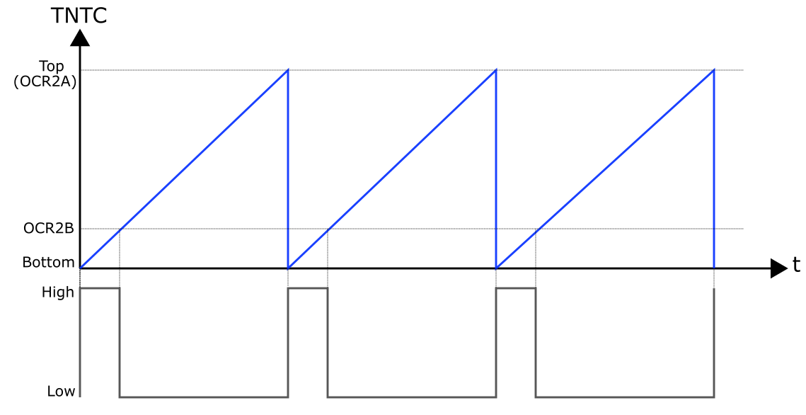
As an example, let’s take Mode 7. The target is a square wave signal with a frequency of 1 kHz at OC2B. Per period, the signal should be HIGH 20% of the time and 80% LOW. Another expression for this is: the duty cycle is 20%.
We set the COM2B1 bit for this purpose. According to the table, this means: “clear OC2B at Compare Match, set OC2B at BOTTOM”. The Compare Match refers to the value stored in OCR2B. Graphically, it looks like this:
First, we have to do some calculations again. We need the top value for the frequency and the value for OCR2B for the duty cycle. Because of the high frequency, we don’t need a scale factor. The following applies:
![\[ f_{desired}=\frac{system\_clock}{prescaler\cdot(1+Top)} \]](https://wolles-elektronikkiste.de/wp-content/ql-cache/quicklatex.com-01a9450589a2d54bf0bd426652063342_l3.png "Rendered by QuickLaTeX.com")
![\[ Top=\frac{16000}{prescaler}-1\;\;\;\;with\;\;\;\;clock=16000000\;\;\;\; und \;\;\;\;f=1000 \]](https://wolles-elektronikkiste.de/wp-content/ql-cache/quicklatex.com-eefa47457d62271fa19c6666dfc34749_l3.png "Rendered by QuickLaTeX.com")
A prescaler of 64 results in 249 for top. That’s 250 steps. One-fifth of it is 50. Since the counter starts at 0, OCR2B is 49, at least theoretically. In practice, you have to try it out. I have hit the desired signal better with the pairing 249 / 50. Of course, it also depends on how exactly the microcontroller clocks.
Here’s what the sketch looks like:
// Period = 1 ms => Frequenz = 1kHz
void setup(){
  // WGM22/WGM21/WGM20 all set -> Mode 7, fast PWM
  TCCR2A = (1<<COM2B1) + (1<<WGM21) + (1<<WGM20); // Set OC2B at bottom, clear OC2B at compare match
  TCCR2B = (1<<CS22) + (1<<WGM22); // prescaler = 64;
  OCR2A = 249;
  OCR2B = 49;
  DDRD |= (1<<PD3);
}

void loop() {}
… and this is what it looks like on the oscilloscope:
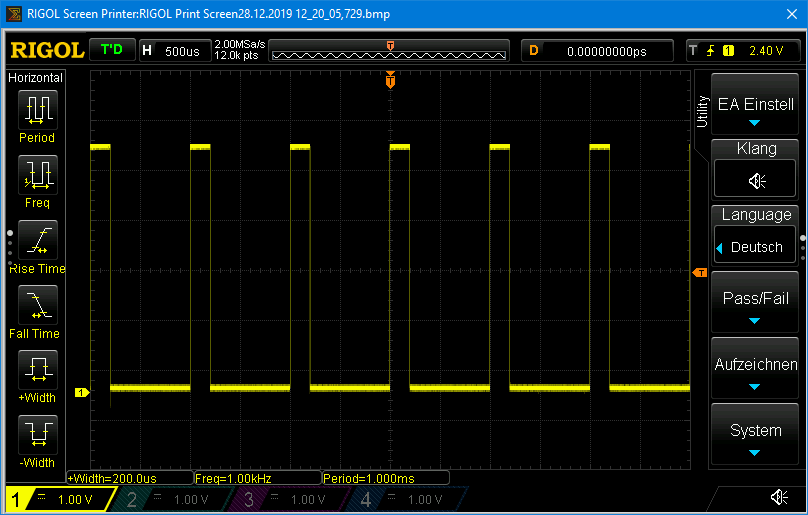
Fast PWM on OC2A
For a PWM signal on OC2A, Mode 7 is of limited suitability, as the Compare Match is equal to Top. There is no possibility to divide the signal into a HIGH and a LOW part. For better understanding you might look into the corresponding tables. In Mode 3, the timer counts up to 255, so any duty cycles can be realized there. The disadvantage, however, is that not any frequency can be set because Top is fixed.
PWM signals with 50% duty cycle, on the other hand, are easy to set on OC2A. This is what you do with the combination: Mode 7 / set COM2A0. According to the table, this means: Toggle O2CA on Compare Match. The period is doubled (frequency is halved).
// Period = 2 ms / Frequenz = 500 Hz.
void setup(){
  // WGM22/WGM21/WGM20 all set -> Mode 7, fast PWM, TOP = OCR2A
  TCCR2A = (1<<COM2A0) + (1<<WGM21) + (1<<WGM20); // Toggle OC2A at compare match
  TCCR2B = (1<<CS22) + (1<<WGM22); // prescaler = 64;
  OCR2A = 249;
  DDRB |= (1<<PB3); // PB3 = OC2A = Arduino Pin 11
}

void loop() {
}
AnalogWrite – a PWM application
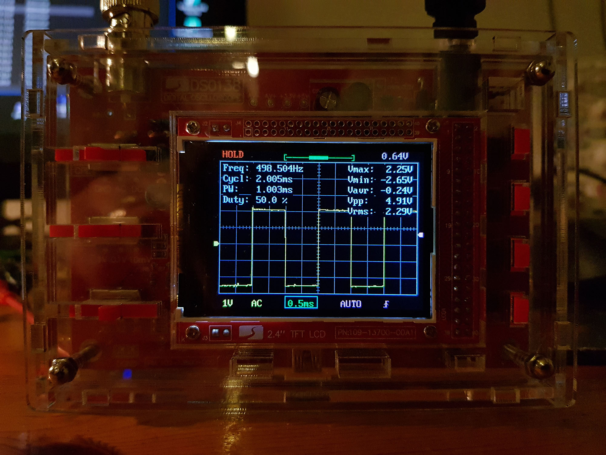
You can see on the oscilloscope that analogWrite is not an analog but a PWM signal:

You don’t have an oscilloscope?
Some may be frustrated that they cannot check the result of the Fast PWM sketches because they do not have an oscilloscope. Three suggestions:
- also in Fast PWM mode you can work with Compare Match Interrupts, insert a counter in the ISR and observe the PWM signal in slow motion. You can even set OCIE2A and OCIE2B and use two ISR routines (TIMER2_COMPA_vect / TIMER2_COMPB_vect).
- uses the technology explained in my post about IR remote controls to analyze fast signals
- buy a DSO 138 oscilloscope for less than 30 euros. Search for it on Amazon or eBay. This device works amazingly well:
The timer in Phase Correct PWM Mode
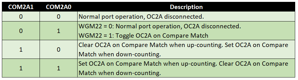
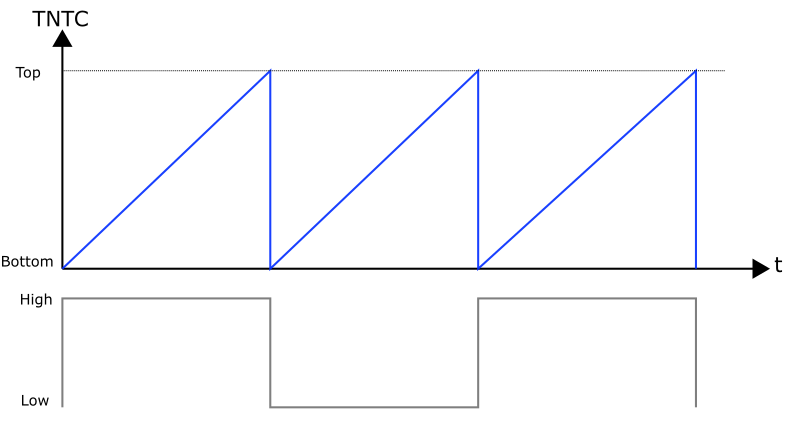
In phase-correct PWM mode (Phase Correct PWM Mode), the counter counts up from BOTTOM to TOP and then down again to BOTTOM. As an example, let’s take the combination of Mode 5 and COM2B1 set, i.e.: “Clear OC2B when up-counting, set OC2B when down-counting”.
Graphically, this looks like this:

This halves the frequency compared to the Fast PWM method.
Phase correct means that the reversal points from HIGH to LOW (or vice versa) are at the same distance before and after the bottom or top of the timer. This results in a symmetric signal, even if the OCR2B Compare value is changed dynamically. A very helpful animation, which shows the difference to the Fast PWM, can be found here. The phase-correct PWM is mainly used for motor controllers. If you want to know more about the PWM modes, see e.g. here. There is another PWM mode, namely the “phase- and frequency-correct PWM” mode. This subject will be treated part 2 (16 bit timer). There I will also go into a little more detail about the differences of the PWM modes.
And here’s a sketch example:
// Period = 2 ms
void setup(){
  // WGM22/WGM20 all set -> Mode 5, phase correct PWM
  TCCR2A = (1<<COM2B1) + (1<<WGM20); // Set OC2A at bottom, clear OC2B at compare match
  TCCR2B = (1<<CS22) + (1<<WGM22); // prescaler = 64;
  OCR2A = 249;
  OCR2B = 49;
  DDRD |= (1<<PD3);
}

void loop() { }
Timer 0 vs. Timer 2
As mentioned above, the structure of Timer0 and Timer2 is very similar. You can see the main difference in the Clock Select Bit table for the timer0:

There are fewer prescalers to choose from, instead you can use an external clock here. You connect it to T0 (PD4, Arduino pin 4). In addition, you can choose whether to count at the rising or falling edge.
Simple example of external clocks
As a clock, we use a simple push button. The OC0A output pin (PD6, Arduino Pin 6) is connected to an LED.
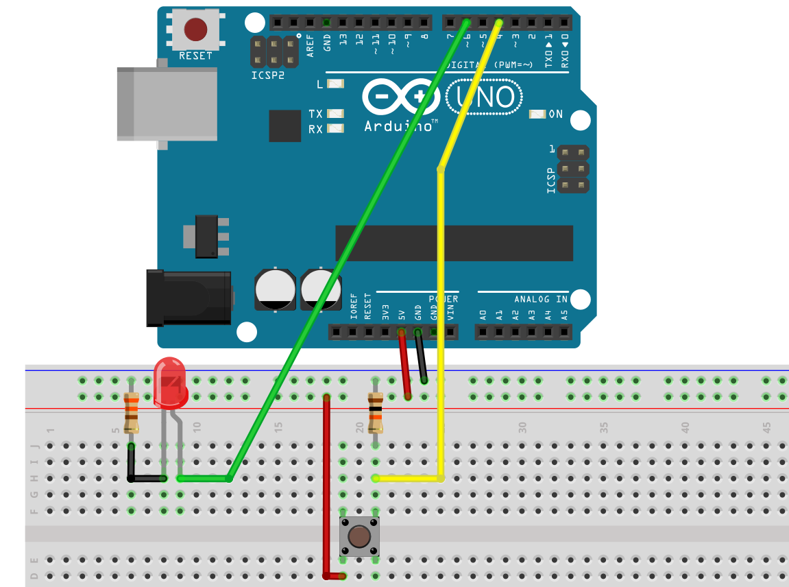
Now let’s choose Mode 7 and set all CS0x bits (Clock on rising edge). OCR0A we set to 10.
void setup(){
  TCCR0A = (1<<COM0A0) + (1<<WGM01) + (1<<WGM00); // WGM 7: fast PWM; since WGM02 = 1 --> Toggle OC0A on Compare Match;
  TCCR0B = (1<<CS02) + (1<<CS01) + (1<<CS00) + (1<<WGM02);  // External clock source on T0 (rising edge)
  OCR0A = 10;
  TCNT0 = 0;
  DDRD |= (1<<PD6);
}

void loop() {
}
Theoretically, the LED should switch on or off every eleventh press of the push button. The LED switches accordingly earlier by pushing the button.
Counting external events in the background can be very useful for certain applications. By the way, there are also special counter ICs, which I have described here.
If you use a clock quartz as a clock set, you can build a quartz watch. This is described in detail here. Pretty cool.
Help for the Timer and PWM programming
Timer and PWM programming can be quite annoying and confusing. A great help is the tool “Arduino Web Timers” by David Buezas, that is available here. I really highly recommend it.
Using Microchip (Atmel) Studio
At the very beginning I mentioned that the Timer0 Overflow Interrupt is not accessible in the Arduino environment. If you use the free software Microchip Studio (formerly known as Atmel Studio), you do not have this limitation. An introduction to Microchip Studio can be found here. You have to invest some time to get used to it, but it’s worth it from my point of view.
The sketch for the two asynchronously flashing LEDs, transferred to the Timer0, looks like this in Atmel Studio:
#include <avr/io.h>
#include <util/delay.h>
#include <avr/interrupt.h>
uint8_t counterStart = 131;
uint16_t scaleFactor = 500;

int main(void)
{
  TCCR0A = 0x00; // OC0A and OC0B disconnected; Wave Form Generation Mode 0: Normal Mode
  TCCR0B = (1<<CS02); // prescaler = 256
  TIMSK0 = (1<<TOIE0); // interrupt when TCNT0 is overflowed
  TCNT0 = counterStart;
  DDRB |= (1<<PB1) + (1<<PB0);
  sei();  // activate interrupts

  while (1)
  {
    PORTB ^= (1<<PB0);
    _delay_ms(723);
  }
}


ISR(TIMER0_OVF_vect)
{
  static int counter = 0;
  TCNT0 = counterStart;
  counter++;
  if(counter==scaleFactor)
  {
    PORTB ^= (1<<PB1);
    counter = 0;
  }
}
Final words
So, I hope one or the other has persevered up to here. Personally, I found it very exciting when I had my first experiences with the timers and got a deeper insight into the inner structure of the ATmega328P.
What follows is, as announced above, part 2, which deals with the 16 bit Timer1.
Acknowledgement
I owe the hourglass in the post image “derGestalterCottbus” on Pixabay.
Excellent article!
🙂 Thank you
Thanks for the explanation, but I have a question:
The processor clock speed of the ATmega328p is 16MHz.
a) The following Timer2 registers of the ATmega328p are configured as follows:
TCCR2A = 0x23;
TCCR2B = 0xD;
OCR2A = 124;
OCR2B = 49;
To which clock speed is the Timer2 clocked down using the prescaler?
which formula ist correct:
Takt= Prozessortakt /Prescaler
or
Takt= Prozessortakt /Prescaler * 256(8-bit timer)
Hi,
if I calculate hexadecimal into binary correctly, then you have set fast PWM mode 7 and prescaler 128. The system clock is 16 mhz. With a prescaler of 128 the timer counts at a frequency of 16 mhz / 128 = 125 kHz. Your top is OCR2A + 1 = 125. That means top is reached at a frequency of 1 kHz (125 kHz / 125). This your PWM frequency. I hope this helps.
Excellent writeup, Wolfgang. Things are much better understood now. I have question, thought. Is that possible to change width of the signal in example timer2_normal_mode_genau_1Hz.ino ?
Thanks.
You could do something like:
  if( (PIND & (1<<PD7)) && (counter==scaleFactor1)) {
    PORTD &= (1<<PD7);
    counter = 0;
  }
  else if( !(PIND & (1<<PD7)) && (counter==scaleFactor2) {
    PORTD |= (1<<PD7);
    counter = 0;
}
And thanks for the feedback!
is it possible to get 0.5 Hz and a sawtooth waveform by using timer0?
A simple question, a complex answer: Of course, you will never get a real sawtooth waveform, since you still work with PWM. You can stepwise increase and decrease the duty cycle. I.e. the rising and falling flanks consist of 256 steps. And each step is a certain number PWM cycles. No problem with Timer2, but an issue with Timer0 when you are working in the Arduino environment. So, let me start with Timer2 and then come back to Timer0. If your clock is 16 MHz and prescaler is 1, the PWM frequency is 16 MHz/256 = 62.5 kHz. If you want to use 256 steps, and you would use one PWM period per step, the maximum frequency per flank is 62.5 kHz / 256 = ~244.14 Hz. You say you would like to achieve a frequency of 0.5 seconds for your sawtooth waveform. Then I assume you mean two flanks (one rising, one falling) per 0.5 seconds. That would mean ~ 244.14 / 4 = ~ 61 PWM cycles per step. With Timer2, you could use the overflow interrupt to count the cycles.
This works:
volatile int counter = 0;
volatile bool makeStep = false;

ISR(TIMER2_OVF_vect){
  if(counter < 61){
    counter++;
  }
  else{
    counter=0;
    makeStep = true;
  }
}

void setup(){
  TCCR2A = (1<<COM2B1) + (1<<WGM21) + (1<<WGM20);
  TCCR2B = (1<<CS20) + (1<<WGM22);
  OCR2A = 255;
  OCR2B = 0;
  TIMSK2 = (1<<TOIE2);
  DDRD |= (1<<PD3);
}

void loop() {
  static bool upward = true;
  static byte step = 0;
  if(makeStep){
    if(upward && (step<255)){
      step++;
    }
    if(!upward && (step>0)){
      step--;
    }
    OCR2B = step;
    if(upward && (step == 255)){
      upward = false;
    }
    if(!upward && (step == 0)){
      upward = true;
    }
    makeStep = false;
  }
}
Now we come to Timer0: the issue is that you can’t use the overflow interrupt because it is needed for millis() and delay(). And if you change the prescaler of Timer0, millis() and delay() won’t work correctly anymore. I you don’t work in the Arduino environment, you don’t have this problem.
Thanks Wolfgang, very thanks. I thought there was a formula to find the ‘scale factor’. The trick is to play with the number: that is valid. Now I can continue with the rest of this exelent tutorial.
I am on “Further downgrade of the frequency” section. From where did you get the “scale factor” of 1000 or 500? I found the equations are difficult. Could you explain them a little more?
The theory and the basic Timer/Counter of AVR MCUs, is excellent. I wanted to take some notes about the important explanation points, and end copying the whole writing until the first example. I really liked it.
Thanks a lot, you really helped me to understand almost the most difficult topics an AVR microcontrolers.
Hi Pedro,
let me try. The counter counts at the frequency of your microcontroller. If you use an Arduino based on an ATmega328P (e. g. UNO, Nano, Pro Mini) it’s 16 MHz. The Timer0/Timer2 register is 1 byte. Every time it exceeds 255 the overflow interrupt is triggered. This happens at a frequency of
f = 16 MHz / 256 = 62.5 kHz
which is by far too fast for something like a blinking LED. To slow it down, you can use the prescaler. If you use the maximum prescaler which is 1024 the frequency of overflow interrupts is
f = 16 MHz / (256 * 1024) = ~ 61.035… Hz.
Not convenient to “play” with and still quite a high frequency. But no chance to further slow down the frequency of overflow interrupts. The trick is to count the interrupts and switch your your LED on or off let’s say every 10th overflow. That means the frequency goes down to
f = 16 MHz / (256 * 1024 * 10) = 6.1035… Hz.
In general terms:
f = system_clock / (timer_counter_size * prescaler * scalefactor).
But still, you have the issue that the frequency is a decimal number. With integers it’s easier to play with. For this finetuning you apply another trick. You let the counter not start at 0, but at a certain starting value. The counts to the overflow is then not 256 anymore, but 256 – starting value. For the equation, that means:
f = system_clock/ ( (timer_counter_size – starting_value) * prescaler * scalefactor).
If you then solve the equation by the starting value, you get (I omit all the steps):
starting_value = timer_counter_size – system_clock / (f * prescaler * scalefactor)
Let’s say the desired frequency is 1 Hz and the system clock is 16 MHz. The timer counter size is fixed (256). That means:
starting_value = 256 – 16000000 / (1 * prescaler * scale_factor).
The problem is now that you can vary two parameters: the prescaler and the scale factor. In other words: there is potentially more than one solution. The prescaler can only be 1024, 256, 128, 64, 32 or 8. You can put in these numbers and play a bit. If you take a prescaler of 1024, the equation is:
starting_value = 256 – 15625/scale_factor
The scale_factor needs to deliver a starting value which is > 1 and < 256 and it should be an integer, not a decimal number. I have just discovered that 125 would work. So, a prescaler of 1024 is not as bad as I wrote in the post.
So, you have to play a bit with the numbers. The fact that the starting number needs to be an integer is the difficulty. To make it systematically, you can do a prime factorization.
15625 = 5 * 5 * 5 * 5 * 5 * 5
Try scale_factor 5 -> starting_value = -2869 -> does not fit
Try scale_factor 5*5 = 25 -> starting_value = -369 -> does not fit
Try scale_factor 5*5*5 = 125 -> starting value = 125 -> fits!
Prescaler = 256 => starting_value = 256 – 62500/scale_factor
62500 = 4 * 5 * 5 * 5 * 5 * 5 * 5
Try scale_factor 4 -> starting_value = -15369 -> does not fit
I omit the next tries and go to 4 * 5 * 5 * 5 = 500 -> starting_value = 131
I hope this makes it clearer.
Thanks Wolfgang, very thanks. I thought there was a formula to find the ‘scale factor’. The trick is to play with the number: that is valid. Now I can continue with the rest of this exelent tutorial.
Well this article really gave me an understand of the Arduino timers, I was so confused before it. I have just one question in the Wave Form Generation Mode 0 and The timer in CTC mode from above shouldn’t the frequency be half of what your showing. Both mode use a saw tooth to form the wave and it takes two cycles to form the one period. If the saw tooth has a frequency of 16MHz using two per cycle would reduce it to 8MHz in the calculations?
Hi David, do you refer to the examples “timer2_normal_mode_minimum_frequenz.ino” and “timer2_ctc_mode_genau_1Hz.ino”? Maybe the term frequency is ambiguous for these examples. The calculations will tell you the frequency of the timer overflow. The frequency of the saw tooth signal is half because you need two timer overflows to get through one low and one high states. Is this what you mean?
Thanks for your excellent explanation about timers and interrupts. I used it to build an Arduino Nano circuit which generates 50Hz AC for a “Faller 180629 Synchronous hobby motor” on my model railroad layout. I’m using a 10ms timer2 interrupt and a digital output pin to generate a 16V 50Hz square wave for the motor.
In Europe, these motors are easily powered by the 14-16VAC from a model railroad power supply. But I live in the US which has 60Hz household power. The motors have trouble starting on 60Hz and run too fast.
____
Gerd
Hi Gerd, thanks for your feeback. It’s always great to hear that my articles helped someone. And in particular when it’s someone far away from Germany. Nice website that you have, I like the waterskiing photos. Best wishes!
Nice and educative article. But, am having a challenge making timer 2 examples in normal mode to work. it compiles but does not work. I will try other modes later.
If you don’t get it right, you can send me your code and tell me what you want to achieve. To: wolfgang.ewald@wolles-elektronikkiste.de
it is a very useful article. helped me a lot. thanks
Thanks for you kind feedback!
A really comprehensive write-up for atmega328p timer and pwm, far better than reading from the datasheet which I found it hard to get a good big picture.
Thank you!