
About this Post
Data transfer via serial, i.e. via the serial port, is one of the first things you come into contact with in the Arduino world, e.g. via Serial.println(). In this article, I will discuss Serial in great detail. Serial is not an overly complex topic, but as with so many things, the devil is in the detail.
I’ll start with a general section in which I explain how the Serial data transfer works and what settings you can make. You will then learn how to make different microcontroller boards communicate with each other via (Hardware-)Serial or SoftwareSerial. In the last part of the article, I go into the Serial functions. A more compact overview of functions for quick reference is already available here on the Arduino pages, but I have more examples and tips on various pitfalls.
Here is an overview of the content of the article:
- What is Serial?
- How does Serial communication work?
- Settings: Data bits, baud rate, parity and stop bits
- Advantages and disadvantages of Serial data transmission
- Serial data buffer
- HardwareSerial communication between MCU boards
- SoftwareSerial
- Serial functions – an overview
What is Serial?
The serial port (Serial) of the Arduino boards is used for communication with the PC, with certain external components or with other microcontrollers. The term “serial” is actually a little vague, as I2C or SPI are also serial forms of communication. To be more precise, the serial port is the USART (= Universal Synchronous/Asynchronous Receiver/Transmitter).
As its name suggests, the USART is capable of synchronous and asynchronous communication. In the Arduino world, however, communication via USART is basically asynchronous. Asynchronous means that there is no line that controls the clock of the communication partners, as is the case with I2C or SPI, for example.
From a programming point of view, Serial is a ready-made instance of the HardwareSerial class, which is part of the standard Arduino package. You therefore do not need to create a Srial object yourself. Many convenient functions are available for Serial. I assume basic knowledge of the common Serial functions. If you have any questions regarding the Serial functions, please refer to the last part of this article, where I discuss them in detail.
How does Serial communication work?
The components participating in serial communication have an RX input (receiver) and a TX output (transmitter). This means that you basically connect RX to TX and TX to RX. If you only want to communicate in one direction, a single TX → RX data line is sufficient. In addition, however, both communication partners must have a common GND, otherwise the HIGH and LOW levels cannot be clearly recognized.
Otherwise, Serial communication is surprisingly simple. In the default state, the RX/TX data line is at HIGH level. If the transmitter wants to transmit something, it pulls the TX line LOW for a certain time. This represents the start bit. One byte is then transmitted, starting with the LSB (Least Significant Bit), i.e. bit 0. A “1” is transmitted as a HIGH signal and a “0” as a LOW signal. After bit 7, the transmitter sends a stop bit (HIGH). The game starts again until all bytes have been transferred. This is how it works when using the default settings.
Using a logic analyzer, I recorded the transmission of a “Hello World!” message from the Serial monitor to an Arduino on the RX pin of the Arduino:
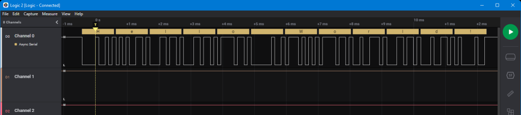
The message is easy to decode because the characters are transmitted in ASCII code. I have broken it down here for the “e” (ASCII code 101) as an example:
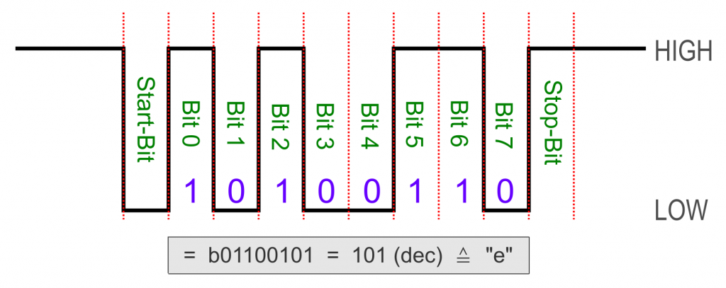
Please note that b01100101 begins with bit 7. The bit sequence must therefore be reversed.
Settings: Data bits, baud rate, parity and stop bits
Serial options
Data bits
Normally, you transmit the data byte by byte, i.e. you send 8 data bits between the start and stop bit. Alternatively, you can also transfer only 5, 6 or 7 bits, but this is rather exotic.
Baud rate
Since there is no separate line for the clock, the transmitter and receiver must have set the same signal length. If, for example, bit 0 is a zero, i.e. LOW, how should the receiver know where the start bit (also LOW) ends and bit 0 begins?
To ensure that the two communication partners understand each other, the same transmission speed is set on both sides as the so-called baud rate (named after Jean-Maurice-Émile Baudot). The baud rate specifies how many HIGH and LOW signals are transmitted per second. At a baud rate of 9600, 960 bytes per second are transmitted, considering the start and stop bits.
Parity bit
To increase the security of the data transfer, you can also send a parity bit. It indicates whether the number of ones in the transmitted byte is even or odd. There are three options:
- None: no parity bit
- Even: Parity bit is 0 if the number of ones is even; otherwise it is 1.
- Odd: Parity bit is 0 if the number of ones is odd; otherwise it is 1.
Stop bits
Instead of one stop bit, you can also transfer two.
How to apply the Serial settings
You are probably familiar with setting the baud rate using Serial.begin(baudrate). The baud rate cannot be selected arbitrarily, but certain values are available for selection. Common settings are between 2400 and 115200 (maximum for the serial monitor).
For the other settings, pass a second parameter: Serial.begin(baudrate, config). The parameter config is “SERIAL_DPS” with:
- D (data bits): 5, 6, 7, 8
- P (parity bit): N (none), O (odd), E (even)
- S (stop bit): 1, 2
If you do not pass a second parameter, the default SERIAL_8N1 will apply.
Receiver and transmitter must have the same setting.
Advantages and disadvantages of Serial data transmission
Advantages:
- Data transmission via a single line possible.
- Simple protocol.
- Widespread distribution.
- Buffered transmission (we’ll come to this in a moment).
Disadvantages:
- No indication whether the receiver is ready to receive the data, as is the case with I2C (acknowledge bit).
- No individual addressing of the receivers, as you can do with I2C via the I2C address or with SPI via the CS line.
- Problems may occur with the program upload in the Arduino environment.
Notes on the last point: A special feature of the Arduino world is that the bootloader redirects the program upload to the serial port. If you only communicate with the serial monitor, you will have no problem with the program upload. The situation is different if you are connected to another device via RX. If this device pulls the RX line up or down, the program upload will no longer work. You will then have to cut the connection during the upload.
One possible solution to the problem is SoftwareSerial. I’ll come back to that later.
Serial data buffer
RX buffer
To understand the RX buffer, let’s go through a practical example. Take an ATmega328P based Arduino board like the UNO R3 or the classic Nano and upload the following program:
void setup() {
  Serial.begin(9600);
 }

void loop() {
  if(Serial.available()){
    String inputString = Serial.readString();
    Serial.print("I received: ");
    Serial.println(inputString);
  }
  // Serial.println("Delay begins...");
  // delay(10000);
}
Open the serial monitor and send a message of 100 characters, e.g:
“123456789 123456789 123456789 123456789 123456789 123456789 123456789 123456789 123456789 123456789”.
As expected, you should see the following on the serial monitor:

Serial.available() checks whether data has been received via the serial port. Serial.readString() retrieves the data and returns it as a string data type.
Now uncomment lines 11 and 12, upload the program and send the same message again after “Delay begins …” has appeared on the serial monitor. Now you will see the following after the delay has expired:

The data ends after 63 characters, although there is still the invisible character no. 64, namely the zero terminator (‘\0’). What is actually remarkable here is not only that fewer data is received as sent, but that data is accepted at all.
The reason for this behavior is the RX buffer, which is set to 64 characters on ATmega328P based Arduino boards (63 of which are usable). The buffer accepts data even if the Arduino is busy with something else, such as the delay in this case. If the data is continuously retrieved from the buffer, there is always enough space in the buffer to receive all the data sent. If this is not the case, the buffer overflows and all additional data is lost. If you repeat the experiment with an ESP32, for example, you will receive the complete data with and without delay because the ESP32’s buffer is 256 bytes.
TX buffer
The fact that the data output is also buffered can be shown with the following sketch:
#include <avr/sleep.h>
#define INT_PIN 2

void setup() {
  Serial.begin(9600);
  set_sleep_mode(SLEEP_MODE_PWR_DOWN);
  pinMode(INT_PIN, INPUT_PULLUP);
  attachInterrupt(digitalPinToInterrupt(INT_PIN), wakeISR, RISING);
 }

void loop() {
  delay(3000);
  Serial.println("Hi, I am going to sleep for a while...");
  //Serial.flush();
  delay(10);
  sleep_mode();
  Serial.println("Woke up!");
}

void wakeISR(){}
The sketch sends the Arduino to sleep after 3 seconds. Before that, however, it should output a message on the serial monitor. A LOW signal on interrupt pin 2 wakes up the Arduino again. The first output of the sketch looks like this:

Part of the message is therefore initially ‘swallowed’, but continues to be output after the wake-up (for this, simply connect pin 2 briefly to GND):

If you extend the delay(10), more is displayed; if you shorten it, less is displayed before sleep.
The Serial.println() instruction initially only pushes the data to be output into the TX buffer. While the program continues to run, the actual output takes place in the background via the TX pin. The output process therefore does not take place sequentially as part of the program, but in parallel. In most cases, this is desirable as it is not blocking, but not in this particular case.
If you do not want to continue with the next steps of the program until the TX buffer has been entirely emptied, use Serial.flush(). Uncomment line 14 and you will see that the message appears in full on the serial monitor before the Arduino goes to sleep.
Enlarging the RX / TX buffer
You can enlarge the RX and TX buffers if necessary, but you must be aware that you will have less SRAM available as a result.
For boards covered by the Arduino board package, set the buffer size in HardwareSerial.h. For me, it is in the following directory:
C:\Users\Ewald\AppData\Local\Arduino15\packages\arduino\hardware\avr\1.8.6\cores\arduino
For boards with an SRAM larger than 1024 bytes, SERIAL_TX_BUFFER_SIZE or SERIAL_RX_BUFFER_SIZE is set by default to 64 bytes, otherwise to 16:
#if !defined(SERIAL_TX_BUFFER_SIZE)
#if ((RAMEND - RAMSTART) < 1023)
#define SERIAL_TX_BUFFER_SIZE 16
#else
#define SERIAL_TX_BUFFER_SIZE 64
#endif
#endif
#if !defined(SERIAL_RX_BUFFER_SIZE)
#if ((RAMEND - RAMSTART) < 1023)
#define SERIAL_RX_BUFFER_SIZE 16
#else
#define SERIAL_RX_BUFFER_SIZE 64
#endif
#endif
#if (SERIAL_TX_BUFFER_SIZE>256)
typedef uint16_t tx_buffer_index_t;
#else
typedef uint8_t tx_buffer_index_t;
#endif
#if  (SERIAL_RX_BUFFER_SIZE>256)
typedef uint16_t rx_buffer_index_t;
#else
typedef uint8_t rx_buffer_index_t;
#endif
Change the value, save the file and upload your sketch again.
For other boards you have to go to the “packages” directory and search for HardwareSerial.h there.
HardwareSerial communication between MCU boards
Now we will let different microcontroller boards communicate with each other via Serial. It is helpful if the boards are equipped with several serial ports.
Boards with one HardwareSerial port
First of all: I recommend SoftwareSerial for this case. Nevertheless, I also want to show how it works via HardwareSerial.
Connect two microcontroller boards as follows:

In this example, the transmitter board shall inform the receiver board of its millis() time every three seconds. Upload this sketch to the transmitter board:
void setup() {
  Serial.begin(9600);
}

void loop() {
  unsigned long int secondsSinceStart = millis() / 1000;
  Serial.print(secondsSinceStart);
  delay(3000);
}
And this is the sketch for the receiving board:
void setup() {
  Serial.begin(9600);
}

void loop() {
  if(Serial.available()){
    unsigned int timeInSeconds = Serial.parseInt();
    Serial.print("Seconds elapsed on the other Arduino: ");
    Serial.println(timeInSeconds);
  }
}
If you try to upload the receiver sketch, you will see that it does not work. The problem is that the TX pin of the transmitter holds the RX pin of the receiver HIGH, and this interferes with the program upload. Disconnect the RX/TX line for the program upload.
Here is the output on the receiver side:

The output on the transmitter side is less nice because I used print() and not println(). However, the function println() also sends the control characters for the line feed and carriage return. In it, parseInt() does not find a number and returns a 0.
In principle, the sketch and the circuit could be extended so that communication takes place in both directions. However, if you then output the received messages with Serial.print() on the serial monitor, you send them also back to the sender at the same time, and you end up in a quick ping-pong. HardwareSerial therefore has its pitfalls.
Boards with multiple HardwareSerial ports
We repeat the last example with two boards that have several serial ports. To do this, we use an Arduino Mega 2560 and an ESP32 board as illustrative objects. For the communication from board to board we will use serial port 2 (“Serial2”) of the Mega 2560 and serial port 1 (“Serial1”) of the ESP32. Transmission to the serial monitor takes place via the default port.
The TX and RX pins are fixed on the Mega 2560. On the ESP32, however, the serial ports can be assigned to other pins.
By using different ports for board-to-board and board-to-PC communication, we avoid the problems of 2-way communication described in the last example.
In this example, however, we have to consider the different operating voltage of the ESP32 and the Mega board. Since the TX pin pulls up the voltage and the Arduino Mega 2560 has the higher voltage, we have to use a voltage divider or level shifter at this point.
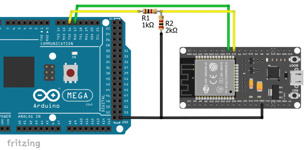
The Mega 2560 informs the ESP32 of its millis() time and receives a confirmation of receipt. Here is the sketch for the Mega 2560:
unsigned long int lastMessageSent = 0;
void setup() {
  Serial.begin(9600);
  Serial2.begin(9600); // both Serial Ports have to initialized!
}

void loop() {
  if(millis() - lastMessageSent > 3000){
    lastMessageSent = millis();
    unsigned long int elapsedTime = lastMessageSent/1000;
    String messageOut = "Hi ESP32, I started " + String(elapsedTime) + " seconds ago";
    Serial2.print(messageOut);
  }

  if(Serial2.available()){
    String messageIn = Serial2.readString();
    Serial.print("Received Message: ");
    Serial.println(messageIn);
  }
}
On the ESP32 side, we assign Serial1 to pins 18 (RX) and 19 (TX). The ESP32 waits for the messages to arrive, reads them in as a string, outputs them on the serial monitor and thanks the Mega 2560.
#define RX1 18
#define TX1 19

void setup() {
  Serial.begin(9600);
  Serial1.begin(9600, SERIAL_8N1, RX1, TX1);
}

void loop() {
  if(Serial1.available()){
    String messageIn = Serial1.readString();
    Serial.print("I received: ");
    Serial.println(messageIn);
    Serial1.print("Hi Mega, thank you!");
  }
}
This is the output on the serial monitor:

Alternative example
In another example, I would like to show you how to send messages from one serial monitor to another. Here, the messages are not read from the buffer in one go, but each individual character received is output immediately on the serial monitor.
Here is the sketch for the Mega 2560:
void setup() {
  Serial.begin(9600);
  Serial2.begin(9600);
}

void loop() {
  if (Serial2.available()) {
    Serial.write(Serial2.read());
  }
  if (Serial.available()) {
    Serial2.write(Serial.read());
  }
}
And here is the sketch for the ESP32:
#define RX1 18
#define TX1 19

void setup() {
  Serial.begin(9600);
  Serial1.begin(9600, SERIAL_8N1, RX1, TX1);
}

void loop() {
  if (Serial1.available()) {
    Serial.write(Serial1.read());
  }
  if (Serial.available()) {
    Serial1.write(Serial.read());
  }
}
SoftwareSerial
What is SoftwareSerial?
SoftwareSerial is, as the name suggests, a software solution that gives ordinary I/O pins the same behavior and functionality as hardware serial pins. From a performance point of view, it is better to use HardwareSerial, as the serial port has hardware components such as the baud rate generator, which have to be emulated by SoftwareSerial. And this costs system resources that may be lacking elsewhere.
If you only have one serial port available on your board and want to avoid problems with program uploads and interactions with the serial monitor, then in most cases there is no real disadvantage in using SoftwareSerial. SoftwareSerial is an inherent part of most board packages. And where this is not the case (e.g. ESP32), there are usually SoftwareSerial libraries available on GitHub.
If you use several SoftwareSerial instances, please note that only one instance can receive data at a time. This means that if several SoftwareSerial RX pins are addressed at the same time, there is a risk of data loss. Here you could or should secure yourself with confirmations of receipt.
How to use SoftwareSerial
The functional principle remains the same, including the buffers. All Serial functions are also available for SoftwareSerial. Handling therefore requires little familiarization. All you have to do is include SoftwareSerial.h and create a SoftwareSerial object:
#include<SoftwareSerial.h>
SoftwareSerial mySerial( RX_Pin, TX_Pin );
You can freely choose RX and TX.
SoftwareSerial example
As an example, we let two Arduino Nano boards communicate with each other via SoftwareSerial on pins 10 and 11. Here, too, we must not forget the GND connection.
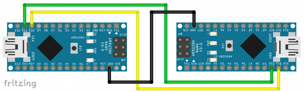
The sketch is identical for both boards.
#include <SoftwareSerial.h>

SoftwareSerial mySerial(10,11); // create a SoftwareSerial object

void setup() {
  Serial.begin(9600);
  mySerial.begin(9600);
}

void loop() {
  if (mySerial.available()) {
    Serial.write(mySerial.read());
  }
  if (Serial.available()) {
    mySerial.write(Serial.read());
  }
}
Of course, you can also have different boards communicate via SoftwareSerial. It is also possible to use HardwareSerial on one board and SoftwareSerial on the other. But always remember the level shifting when the boards use different operating voltage.
Serial functions – an overview
Functions for writing
For a better understanding of the writing functions, you should bear in mind that all characters to be transferred are finally translated into ASCII code. The main difference between the functions is the interpretation of the arguments passed.
print() / println()
size_t numberOfWrittenBytes = Serial.print( somethingToPrint );
size_t numberOfWrittenBytes = Serial.print( somethingToPrint, format );
Everyone should be familiar with these functions. They are very flexible because you can pass them integers, floats, strings, bytes and more. What some people may not know is that print() and println() return the number of bytes written. And what many people may not have thought about so far is what print() and println() actually transmit.
Quiz question: What does the following line of code display on the serial monitor?
Serial.println(Serial.println(1000));
Firstly, of course, the 1000 appears on the serial monitor and then the return value, which is 6. Two bytes are the line feed (ASCII code: 10) and the carriage return (ASCII code: 13). The “1000” is not transmitted as a number, but as a character string, i.e. the “1” as ASCII code 49 and the “0”s as ASCII code 48. You could therefore just as well use Serial.println("1000");. Serial.print(1000); would return 4, as line feed and carriage return are omitted.
Pointers are not accepted by print()/println(), with the exception of char* (character arrays). Numbers greater than 32 bits (e.g. long long / int64_t) cannot be passed to these functions either.
As format you can specify the desired number system (BIN, OCT, DEC, HEX) for integers and the number of decimal places for floating-point numbers.
Another quiz question: What does Serial.println(Serial.println(1000, BIN); display? Answer: First the 1000 in binary format (= 10-bit number) and then the return value 12. Each bit of the binary number is translated into the ASCII code for 0 or 1 before transmission. Not very effective! The fastest way to transfer numbers is in the hexadecimal system.
write()
size_t numberOfBytesWritten = Serial.write( aByteToWrite);
size_t numberOfBytesWritten = Serial.write( aCharacterArrayToWrite );
size_t numberOfBytesWritten = Serial.write( aCharacterArrayToWrite, length);
In contrast to print(), write() interprets numbers as ASCII code. For example, Serial.write(65); outputs an “A”.
Here is a short sketch that illustrates the use of Serial.write():
void setup() {
  Serial.begin(9600);
  char charArray[6] = "ABCDE";

  Serial.print("Serial.write('A'): ");
  Serial.write('A');
  Serial.println();

  Serial.print("Serial.write(\"A\"): ");
  Serial.write("A");
  Serial.println();

  Serial.print("Serial.write(65) : ");
  Serial.write(65);
  Serial.println();

  Serial.print("Serial.write(321): ");
  Serial.write(321);
  Serial.println();

  Serial.print("Serial.print(Serial.write(65)): ");
  Serial.print(Serial.write(65));
  Serial.println();

  Serial.print("Serial.write(charArray)       : ");
  Serial.write(charArray);
  Serial.println();

  Serial.print("Serial.write(charArray, 3)    : ");
  Serial.write(charArray, 3);
  Serial.println();
}

void loop() {}
And here is the output:

Two comments on this:
Serial.write(65)only returns 1 byte for the reasons described above.- 321 is too big for
Serial.write(). All upper bytes are truncated. 321 / 256 = 1, with the remainder 65. Only the remainder is used.
Functions for reading
The available read functions process the received ASCII code. The functions essentially differ in how the characters are interpreted and how many characters are read at a time.
read() / readBytes() / readBytesUntil() / peek()
1. read()
int incomingByte = Serial.read();
The return value of Serial.read() is an integer (even if byte, uint8_t or char would have sufficed). If the sender sends an “A”, the return value of Serial.read() on the receiver side is the number 65. If you output this value with Serial.println() on the serial monitor, it is interpreted as an integer and “65” appears. With Serial.write() the value is converted to char type, and you get an “A”.
void setup() {
  Serial.begin(9600);
}

void loop() {
  if(Serial.available()) {
    int incomingByte = Serial.read();
    // Serial.find('\n'); // or: find('\r'), empties the buffer
    Serial.println(incomingByte);
    Serial.write(incomingByte);
    Serial.println();
  }
}
If you try the sketch and have not entered “No line ending” in the serial monitor, the line feed and / or the carriage return will also be transmitted. The obvious thing to do is to truncate the characters by emptying the RX buffer after receiving the character. There is no separate function for this. You could use Serial.find('\n') (LF) or Serial.find('\r') (CR), depending on which setting you have selected. But if you search for the wrong character, you block the program for a second (timeout).
2. readBytes()
size_t numberOfBytesWrittenToBuffer = Serial.readBytes( buffer, length );
With Serial.readBytes() you write the read bytes directly into a character array or byte array. The number of the characters to be read is a bit tricky. With a character array, you must ensure that the last character in buffer is reserved for the null terminator (‘\0’). But there are also other things to consider.
Upload the following sketch:
void setup() {
  Serial.begin(9600);
 }

 void loop() {
  char buffer[13] = {'\0'};
  if(Serial.available()) {
    Serial.readBytes(buffer, 12);
    //Serial.find('\n'); // empties the RX buffer in case you set "Both NL & CR"
    Serial.println(buffer);
  }
}
Set the serial monitor to “No line ending”. Then send these three strings (without the quotation marks):
- “Hello World!”
- “Hello World”
- “Hello World!!!”
Message 1 appears without any noticeable delay. 12 characters are available in the RX buffer and are read in immediately.
Message 2 only appears after approx. one second. As there is one character too few in the RX buffer, the program waits 1000 milliseconds to see if another character will arrive in the RX buffer. If not, only the existing characters are written to buffer.
With message 3, “Hello World!” appears immediately. The second exclamation mark remains in the RX buffer and is picked up in the next pass. However, as the number of characters falls below 12, the program waits another second.
Quiz question: What happens when you enter “Hello World!Hello World!”? Try it out.
To cut off all characters after the twelfth, you could uncomment line 9, but accept the timeout delay if the last character is not a line feed. You can create a line feed using the setting “Both NL & CR” or “New line” or aprintln() if you are sending the character string from another board.
3. readBytesUntil()
size_t numberOfBytesWrittenToBuffer = Serial.readBytesUntil( terminatingChar, buffer, length );
The function Serial.readBytesUntil() terminates reading in buffer when it encounters the character being searched for (terminating char), the specified length is reached or in the event of a timeout. We can use this to read in character strings of unknown length but with a defined last character without delay. Upload the following sketch:
void setup() {
  Serial.begin(9600);
 }

 void loop() {
  char buffer[20] = {'\0'};
  if(Serial.available()) {
    Serial.readBytesUntil('\n', buffer, 19);
    Serial.println(buffer);
  }
}
In the serial monitor, set “Both NL & CR” or “New line”. Or, if you are sending the string from another board, do so with println().
4. peek()
int incomingByte = Serial.peek();
Serial.peek() is like Serial.read(), except that the character read is not deleted from the RX buffer.
void setup() {
  Serial.begin(9600);
 }

void loop() {
  if(Serial.available()) {
    int incomingByte = Serial.peek();
    Serial.write(incomingByte);
  }
}
Entering “Hello World!” generates the following output:

readString() / readStringUntil()
String incomingString = Serial.readString();
String incomingString = Serial.readStringUntil( searchChar );
The function readString() reads the content of the RX buffer and returns it as a string. The function waits until the timeout to see whether additional character arrive in the RX buffer. This can be annoying. We’ll come to how you can speed this up soon.
With readStringUntil(searchChar) you initially only read the RX buffer up to searchChar. The character itself is not transferred to the string. If the character you are looking for is not yet the last character, the game starts again with the rest of the RX buffer content.
Here is an example:
void setup() {
  Serial.begin(9600);
 }

void loop() {
  if(Serial.available()) {
    String incomingString = Serial.readStringUntil('o');
    //Serial.readStringUntil('\n'); // empties the RX buffer
    Serial.println(incomingString);
  }
}
If you send “Hello World” via the serial monitor, you will see that the first two fragments are output quickly and the last fragment only after one second due to the timeout.
If you want to ignore the rest of the buffer after the first fragment, uncomment line 8 and pass a line feed by setting “Both NL and CR” in the serial monitor. If you are sending the string from another board, use println() on the transmitter side.
Here is the output:

If you want to read entire strings without delay, you could use readStringUntil('\n');.
Search functions
find() / findUntil()
bool found = Serial.find( searchChar );
bool found = Serial.find( searchChar, length );
bool found = ( Serial.findUntil( *searchArray, *terminatingArray );
Use Serial.find() to read the buffer up to the searchChar you are looking for. If you also enter a length, the function stops at length if searchChar has not been found before. Here is an example:
void setup() {
  Serial.begin(9600);
 }

void loop() {
  if(Serial.available()) {
    Serial.find('l');
    String incomingString = Serial.readString();
    Serial.println(incomingString);
  }
}
Output when “Hello World” is entered:

Alternatively, you can search for a character array before another character array. Strictly speaking, the function only accepts pointers. So it is only “clean” as follows, even if you are only looking for individual characters:
void setup() {
  Serial.begin(9600);
}

void loop() {
  char WArray[2] = "W";
  char oArray[2] = "o";
  if(Serial.available()) {
    if(Serial.findUntil(WArray, oArray)){
      Serial.println("Found a \"W\" before \"o\" or end");
    }
    else {
      Serial.println("No \"W\" before \"o\" or no \"o\"");
    }
  }
}
When using Serial.findUntil('W', 'o'), the compilation aborts with an error message. Serial.findUntil( "W", "o") runs through, but with a warning message, depending on the warning level in the settings of the Arduino IDE.
Entering “Hello Word!” gives the following output:

Explanation: There is no “W” up to the first “o” → false. In the next loop run, the function finds the “W” before the second “o” → true. The function stops after the “W” and searches for another “W” before the “o”. There is no character at all before the “o” → false. There is no “o” in the last section, i.e. false. The timeout kicks in again for the last section. Try something like “Wabcxyzo”. There are also two messages, but both appear promptly because the RX buffer is empty after the “o”.
parseInt() / parseFloat()
parseInt()
long aNumber = parseInt();
long aNumber = parseInt( lookahead );
long aNumber = parseInt( lookahead, ignore );
The function parseInt() searches the buffer for the next integer. Due to its return value, it should actually be called “parseLong”.
Here is an example sketch for the calling the function without parameters:
void setup() {
  Serial.begin(9600);
}

void loop() {
  if(Serial.available()){
    int incomingInt = Serial.parseInt();
    Serial.println(incomingInt);
    incomingInt = Serial.parseInt();
  }
}
Entering “blablabla-42blabla12345” results in:

If you add a “blabla” to the input, you would get a 0 in the last loop.
As a parameter lookahead you can choose between the following options:
- SKIP_ALL: This is the default setting, which also applies if no parameter is passed. All characters except digits and minus are ignored.
- SKIP_NONE: If the first character is not a digit or a minus, the function stops and returns 0.
- SKIP_WHITESPACE: Only spaces, tabs, line feeds and carriage returns are skipped. If the function encounters another character that is not a digit or a minus sign, the function stops and returns 0. On ” -42blabla2345″, the function would find the -42, but then return a 0 in the next run.
The parameter ignore is a character that should be ignored. For example, if you use parseInt( SKIP_ALL, ','), the character string “32,125” will be returned as 32125.
parseFloat()
float aFloat = parseFloat();
float aFloat = parseFloat( lookahead );
float aFloat = parseFloat( lookahead, ignore );
In a nutshell: parseFloat() works in the same way as parseInt(), except that in addition to the digits and minus, dots is also read. The return value is a float.
void setup() {
  Serial.begin(9600);
}

void loop() {
  if(Serial.available()){
    float incomingFloat = Serial.parseFloat();
    Serial.println(incomingFloat);
  }
}
An input of “bla42blabla.bla12.345blab.78labla-4.8” generates the following output on the serial monitor:

Other functions
begin() / end ()
Serial.begin( baudRate );
Serial.begin( baudRate, config );
Serial.end();
I have already explained the use of Serial.begin() here. You can stop Serial with Serial.end(). It is worth considering using this if, for example, you only want to output something to the serial monitor during setup. By ending Serial, you have more SRAM at your disposal.
available() / availableForWrite()
int availableBytes = Serial.available();
int availableBytesToSendWithoutBlocking = Serial.availableForWrite();
Use available() to check whether there is data in the RX buffer and how many bytes are involved. Here is an example sketch:
void setup() {
  Serial.begin(9600);
}

void loop() {
  if(Serial.available()) {
    delay(100);
    int availableBytes = Serial.available();
    Serial.print("Available Bytes: ");
    Serial.println(availableBytes);

    Serial.println(Serial.readString());

    availableBytes = Serial.available();
    Serial.print("Available Bytes: ");
    Serial.println(availableBytes);
  }
}
Enter “Hello World!” in the serial monitor:

The availableForWrite() function checks the free space in the TX buffer. If you want to send or write more bytes than there is space in the buffer, the process will block.
flush()
Serial.flush();
The function makes the program wait until the sending of data from the TX buffer is complete. It is not used to empty the buffer per se. I have already given one example here.
setTimeOut()
void Serial.setTimeout( timeoutInMillisecs );
I have mentioned the timeout several times. You can modify it using setTimeOut(). Here is an example that illustrates how it works:
void setup() {
  Serial.begin(9600);
  for(int i=0; i<5; i++){
    Serial.find('x');
    Serial.println("Timeout!");
  }
  Serial.setTimeout(3000);
  for(int i=0; i<5; i++){
    Serial.find('x');
    Serial.println("Timeout!");
  }
}

void loop() {}
The first for-loop is run every second, the second takes three seconds per run.
if(Serial)
On boards with a native USB interface, such as the Arduino Zero or Micro, use if(Serial) to check whether the serial port is available after you have activated Serial with Serial.begin(). Or you can wait for it to be ready with while(!Serial) { ; }.
serialEvent()
You should no longer use the serialEvent() function. Boards that still support serialEvent() are the UNO R3, the classic Nano, the Mega 2560 R3 and the Due.
If you still want to use it, here’s a simple example:
void serialEvent(){
  Serial.println(Serial.readString());
}

void setup() {
  Serial.begin(9600);
}

void loop() {}
The serialEvent() function is called up at the end of loop() if data is available for retrieval. With Serial.available() you are better off as it is easier to transfer your code to other boards.
Dear Wolfgang;
Congratulations for another excellent article, always very well explained. Hardware Serial is always better than Software Serial which is sometimes limited to high baud rates. Remembering that Nano boards with the 328PB processor are now appearing on the market, which provide another serial port (Serial1) on pins 11 and 12 in addition to the normal one on pins 0 and 1.
Dear Antonio, thank this is very kind, and thanks for the hint on the 328pb based boards!