About this Post
The ATmega328PB is a further development of the good old ATmega328P, which you may know from various boards such as the Arduino UNO R3, the classic Arduino Nano V3 or the Arduino Pro Mini. Compared to the ATmega328P, the ATmega328PB is certainly not a revolution, but it does have some useful additional features.
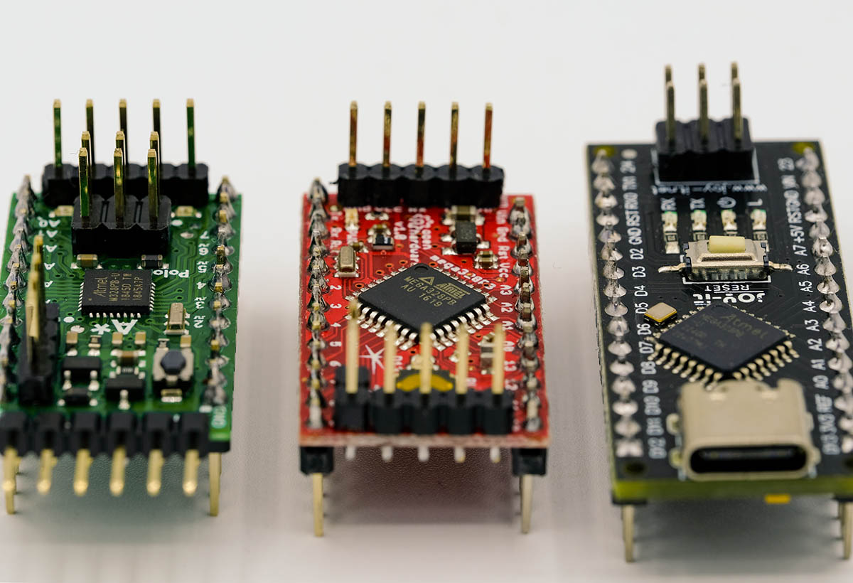
There is now a whole range of boards that are equipped with the ATmega328PB. I took a closer look at the ARD-NanoV4-MC from Joy-IT as a representative of Nano-style boards. The A-Star 328PB Micro from Pololu and the Wattuino Pro Mini PB from Watterott electronic are representatives of the Pro Mini style.
In the article, you will see that the board packages recommended by the manufacturers have implemented the advantages of the ATmega328PB to varying degrees and in different ways. I don’t want to say if better or worse because it depends on your preferences and what you want to do with your board. And nobody is forcing you to use the recommended board package.
This is what you can expect in this article:
- ATmega328PB vs. ATmega328P – Overview
- “Nano-style” board using the example of ARD-NanoV4-MC
- “Pro Mini style” board using the Pololu A-Star 328PB Micro as an example
- Wattuino Pro Mini PB
- Changing the board package
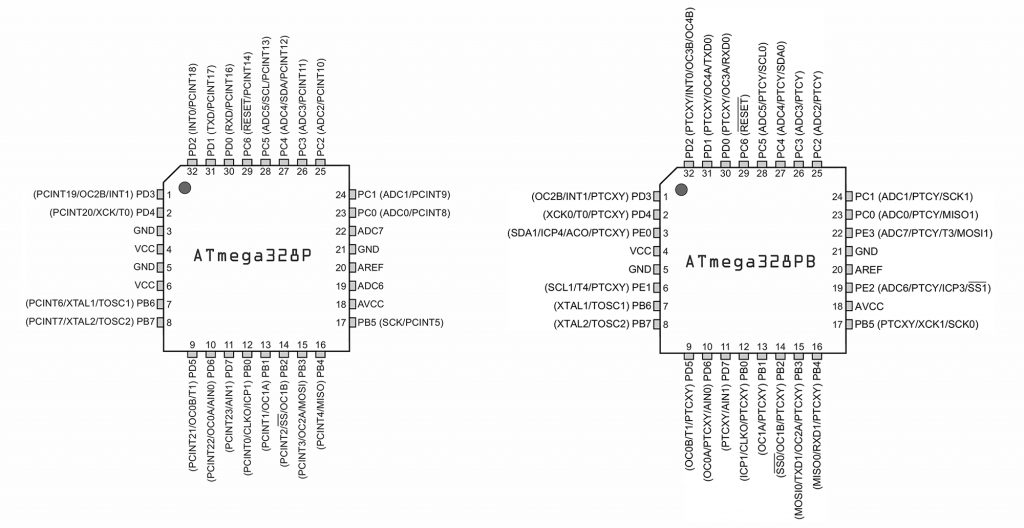
ATmega328PB vs. ATmega328P – Overview
The ATmega328PB is downwards compatible with the ATmega328P. This means that sketches that you have written for the ATmega328P and boards based on it will also work on the ATmega328PB. You can find a data sheet for the ATmega328PB here at Microchip.
These are the most important changes from my point of view:
- One additional USART (Serial), TWI (I2C) and SPI interface each.
- Two additional 16-bit Timers/Counter (Timer/Counter 3, Timer/Counter 4).
- Four additional I/O pins (PE0, PE1, PE2, PE3).
- One GND and one VCC pin were sacrificed for PE0 and PE1.
- The pins for ADC6 and ADC7 now also have an I/O pin function (PE2 and PE3).
- Output Compare Modulator: combines the outputs of Timer/Counter 3 and Timer/Counter 4 on PD2.
- Analog Comparator Output on PE0.
- PTC: Peripheral Touch Controller. The PTC allows you to evaluate capacitive touch sensors attached to the I/O pins. However, the Atmel Start QTouch® Configurator must be used for this. I’m not going to go into that.
A complete summary of the differences can be found in the application note AN42559 from Microchip.
“Nano-style” board using the example of ARD-NanoV4-MC
I will use the ARD-NanoV4-MC to show how to utilize the additional functions offered by the ATmega328PB. You can also find the board under the name “ARD NANO V4 (MINICORE)”. I call it “NanoV4-MC” for short.
On the Joy-IT website you will find the exemplary documentation of the NanoV4-MC with data sheets and instructions in various languages.
I would like to take this opportunity to say that neither Joy-IT nor Pololu or Watterott pay me in any way for presenting their products.
Installation of the recommended board package
Joy-IT has provided the MiniCore board package from MCUdude for the NanoV4-MC, which you can find here on GitHub.
I will not go into detail about installing board packages in the Arduino IDE. If required, refer to the Joy-IT instructions. Here is the short version:
- In the Arduino IDE, go to File → Preferences.
- Click on the icon next to “Additional boards manager URLs”.
- Add the line: “https://mcudude.github.io/MiniCore/package_MCUdude_MiniCore_index.json” (without quotation marks), then confirm “OK” twice.
- Click on the icon for the board management on the left-hand side of the IDE and enter “MiniCore” as the search term.
- Install MiniCore by MCUdude.
To set the correct board, select “MiniCore → ATmega328” under “Tools → Board”. Moreover, you must specify “328PB” and set the “Clock” to “External 16 MHz”.
Pinout
Here is the pinout (with kind permission of Joy-IT):
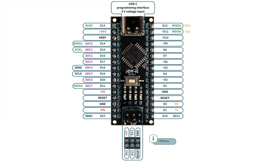
At first glance, it looks like an Arduino Nano. The main differences are:
- Additional pins D23 and D24.
- The second I2C interface (Wire1) is implemented at D23 and D24.
- A6 and A7 can be used as GPIOs (D20/D21).
- The second SPI interface is allocated to pins A0, A1 and A7.
- Serial1 is allocated to pins D11 and D12.
Using Serial1
Since the program upload to Arduino boards is managed via USART (Serial), the use of Serial for other purposes is sometimes problematic. For this reason, most people use SoftwareSerial in such cases, but it is more resource-intensive than HardwareSerial.
I would like to use a simple application example to show you how to use Serial1. First, connect two NanoV4-MC boards as follows:
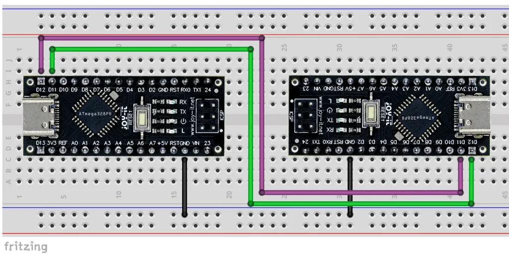
Then upload the following sketch to both NanoV4-MC boards (preferably with different names so that you can open two serial monitors):
void setup() {
  Serial.begin(9600);
  Serial1.begin(9600);
}

void loop() {
  if (Serial1.available()) {
    Serial.write(Serial1.read());
  }
  if (Serial.available()) {
    Serial1.write(Serial.read());
  }
}
Now you can exchange messages using the serial monitor. If you only have a NanoV4-MC available, you can also choose a different board on the other side and use SoftwareSerial there. It is important that the same baud rate is set on both sides. If you are using a 3.3 volt based board on the other side, you will need to add voltage dividers or a level shifter in between. You can find out more about Serial and SoftwareSerial here.
Using Wire1
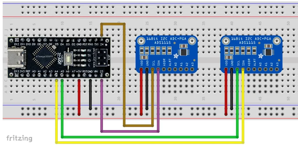
Many external devices are controlled via I2C (Wire). It becomes problematic if you have several devices with the same I2C address. If there are only two devices with the same address, you can control one via Wire and the other via Wire1. The prerequisite is that libraries, if used, allow passing Wire objects. I will show you how to work with Wire and Wire1 in parallel using the ADS1115 as an example.
This is the circuit:
And here is the corresponding sketch:
#include<ADS1115_WE.h>
#include<Wire.h>
#include<Wire1.h>
#define I2C_ADDRESS 0x48

ADS1115_WE adc_0 = ADS1115_WE(&Wire, I2C_ADDRESS);
ADS1115_WE adc_1 = ADS1115_WE(&Wire1, I2C_ADDRESS);

void setup() {
  Wire.begin();
  Wire1.begin();
  Serial.begin(9600);
  if(!adc_0.init()){
    Serial.println("ADS1115 0 not connected!");
  }
  else{
    Serial.println("ADS1115 0 successfully connected!");
  }
  if(!adc_1.init()){
    Serial.println("ADS1115 1 not connected!");
  }
  else{
    Serial.println("ADS1115 1 successfully connected!");
  }
}

void loop() {}
As expected, the output is:

Using SPI1
In principle, you can use SPI1, but passing it to objects does not work as easily as with Wire1. The main problem is that SPI1 has been defined in the MiniCore library as an object of the class “SPI1Class” and most libraries do not recognize “SPI1Class”.
However, direct use of SPI1, i.e. via SPI1.transfer() and Co, is not a problem. If you only want to use SPI1 because you need the standard SPI pins for other purposes, then you could change to the Pololu board package. We’ll come to that later.
Additional Timer / PWM
The ATmega328PB has the additional Timer/Counter 3 and 4. The systematics of the associated registers correspond to that of Timer/Counter 1, which I have described in detail here. The OC3A and OC4A outputs are located at PD0 (RX/D0) and PD1 (TX/D1). Here is a simple example of a PWM signal that is output to OCRA:
void setup(){
  noInterrupts();
  // prescaler: 8, top = ICR3, clear at OCR3A, set at top, output at OC3A
  TCCR3A = (1 << COM3A1) | (1 << WGM31);
  TCCR3B = (1 << WGM33) | (1 << WGM32) | (1 << CS31);
  DDRD = (1 << DDD0); // PD0 to OUTPUT
  OCR3A = 9999;
  ICR3 = 39999; // pwm frequency 50 Hz, duty cycle 25%
  interrupts();
}

void loop() {}
And as always with this topic, I recommend the great tool Arduino Web Timers by David Buezas. With this tool, you can make your settings using tick boxes and do not have to laboriously search for the register settings from the data sheet.
Output Compare Modulator
OC3B and OC4B share pin PD2 (D2) and form the Output Compare Modulator with which you can combine the two PWM signals. There are two settings:
- PD2 is set to HIGH:
- PD2 Level = SignalOC3B | SignalOC4B
- This means that the signals are logically OR-linked.
- PD2 is set to LOW:
- PD2 Level = SignalOC3B & SignalOC4B
- This means that the signals are logically AND-linked.
As an example, we take two PWM signals with a duty cycle of 25%. The PWM frequency of OC4B should be twenty times the PWM frequency of OC3B.
Here’s the sketch:
void setup(){
  noInterrupts();
  // OC3B settings:
  TCCR3A = (1 << COM3B1) | (1 << WGM31);
  TCCR3B = (1 << WGM33) | (1 << WGM32) | (1 << CS31);
  OCR3B = 9999;
  ICR3 = 39999;

  // OC4B settings:
  TCCR4A = (1 << COM4B1) | (1 << WGM41);
  TCCR4B = (1 << WGM43) | (1 << WGM42) | (1 << CS41);
  OCR4B = 399;
  ICR4 = 1999;

  // PD2 settings
  DDRD = (1 << DDD2);
  // PORTD |= (1<<PD2);
  interrupts();
}

void loop() {}
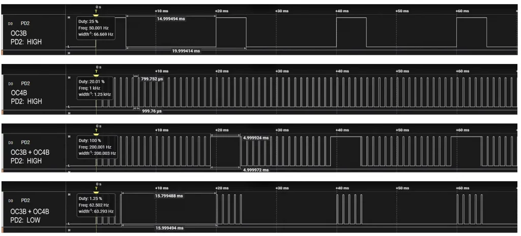
The signal to PD2 depends on whether you leave line 17 commented out or uncomment it. To obtain the individual signals OC3B and OC4B, you must uncomment line 17 and comment lines 4 to 7 and 10 to 13 respectively.
With a Logic Analyzer I got the following outputs:
Analog Comparator Output
The Analog Comparator compares two voltages and indicates which of the two is greater. With the ATmega328P, you have to query the ACO bit (Analog Comparator Output), or set up an interrupt. The ATmega328PB, on the other hand, has an additional ACO pin (PE0 / D23).
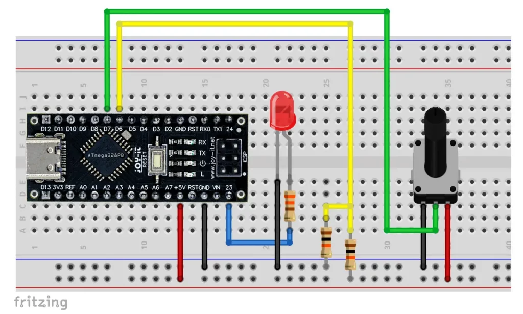
Here is a small example in which we apply half the supply voltage at AIN0 (PD6 / D6) and connect a variable voltage source to AIN1 (PD7 / D7) using a potentiometer. An LED attached to the ACO pin indicates which voltage is higher.
Here is the amazingly short sketch:
void setup() {
  ACSR = 0x00;
  ADCSRB = 0x00;
  ACSRB = (1 << ACOE);  // Analog Comparator Output Enable
}

void loop() {}
If the voltage at D7 is higher than at D6, the LED is off. If the voltage at D7 is lower, the LED is on. The inputs for the Analog Comparator can be multiplexed to all analog pins. But that would be going a bit too far here.
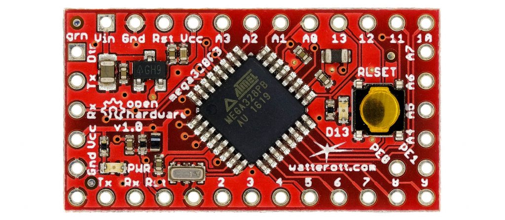
“Pro Mini Style” board using the Pololu A-Star 328PB Micro as an example
If you prefer an ATmega328PB based board in Pro Mini style, you could go for the Pololu A-Star 328PB Micro. It is available in four variants:
- 5 volts – 20 MHz
- 5 volts – 16 MHz
- 3.3 volts – 12 MHz
- 3.3 volts – 8 MHz
Pololu points out that the 20 MHz model is operated outside the specification (max. 16 MHz). I used the 20 MHz version for several hours, and it worked flawlessly – which, of course, is no guarantee!
The A-Star 328PB is also well documented on the Pololu website with instructions, specifications and schematics. There is also a Pololu forum that you can contact if you encounter any problems.
Installation of the recommended board package
The installation in the Arduino IDE is described in detail here on the Pololu website. The ultra-short version is:
- Add the following board manager URL: “https://files.pololu.com/arduino/package_pololu_index.json”.
- Install the board package: “Pololu A-Star Boards”.
- Select the following board: “Pololu A-Star Boards” → “Pololu A-Star 328PB”.
- Set the correct variant in terms of voltage and clock.
Pinout
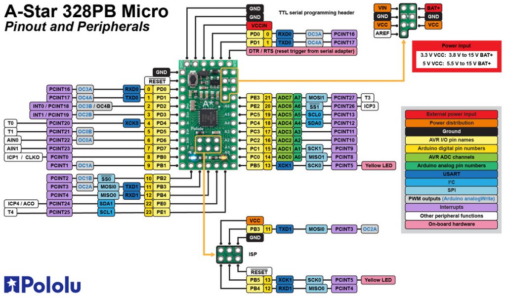
Although the A-Star 328PB Micro has the same dimensions as an Arduino Pro Mini board, the two additional GPIOs PE0 (D22) and PE1 (D23) and AREF are implemented on it. Furthermore, there is a reverse-protected battery input (BAT+), an additional VCC pin and an ISP header. The latter is very practical for uploading via programmer.
Here is the pinout diagram (with kind permission of Pololu):
Sketch upload / burning the bootloader
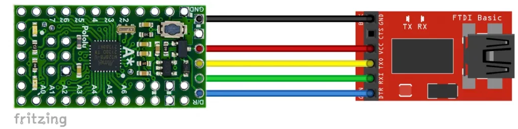
Via Serial with USB-to-TTL adapter
To upload via Serial, you will need a USB-to-TTL adapter (also known as an FTDI adapter). Please note that RX must be connected to TX and TX to RX. In addition, the operating voltage of the adapter must match that of the A-Star 328PB Micro.
If the upload via adapter does not work and aborts with an “acess denied” error message, this could be because the serial monitor is still open. Close it and then it should work.
Upload via ISP / burning the bootloader
If you prefer to upload via ISP, you will need a programmer. The advantage of this method is that you save the memory space for the bootloader (= 512 bytes of flash). The disadvantage is that you have no connection to the serial monitor.
When uploading via ISP, the bootloader is deleted. If you want to switch back to the serial upload, you must first burn the bootloader.
Inexpensive programmers can be found under the search term USBASP or USBtinyISP. I have tested these and various others, and they all worked perfectly.
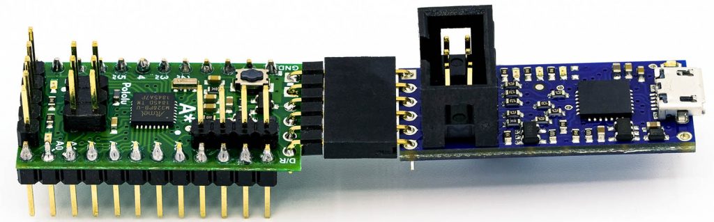
The all-rounder: Pololu USB AVR Programmer v2.1
The Pololu USB AVR Programmer v2.1 is an ideal addition to the A-Star 328BP Micro. It is a USB-to-TTL adapter and an ISP programmer in one. For program upload via serial you can plug it in directly, for programming via ISP you connect the ISP headers.
If you choose this model, I recommend that you read the instructions. Some settings of this programmer, such as the operating voltage, are made via a user interface.
Using Serial1
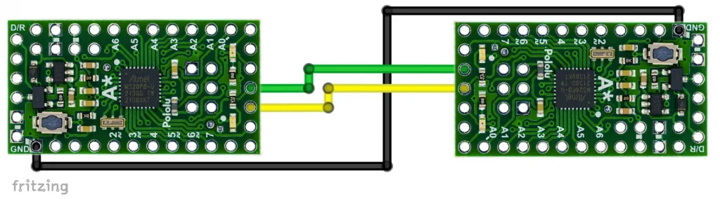
Using Serial1 is just as easy as it is with the NanoV4-MC. As a test, you could let two A-Star 328 PB Micro “talk” to each other. To do this, connect TXD1 to RXD1, RXD1 to TXD1 and GND to GND.
Take nanov4_mc_serial_serial1.ino from above as the sketch.
Using Wire1 and SPI1
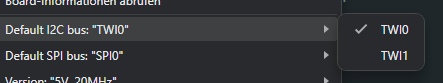
As far as Wire1 and SPI1 are concerned, the Pololu board package takes a different approach to the MiniCore package. Parallel use of Wire (“Wire0” / “TWI0”) and Wire1 or of SPI (“SPI0”) and SPI1 is not possible. Instead, you set which of the interfaces you want to use in the Arduino IDE:
You can switch back and forth, but not within one sketch. As an example, I will show how to control ADXL345 modules via SPI. To do this, I connected one module to SPI0 and the other to SPI1:
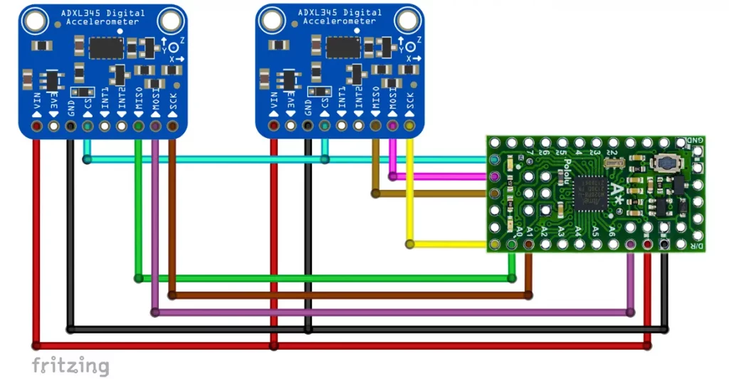
The sketch is the same for both modules and SPI interfaces:
#include<ADXL345_WE.h>
#include<SPI.h>
#define CS_PIN 10   // Chip Select Pin

bool use_spi = true;    // specific for ADXL345_WE
ADXL345_WE myAcc = ADXL345_WE(&SPI, CS_PIN, use_spi);

void setup(){
  Serial.begin(9600);
  Serial.println("ADXL345 SPI-Test");
  if(!myAcc.init()){
    Serial.println("ADXL345 not connected!");
  }
  else {
    Serial.println("ADXL345 successfully connected!");
  }
}

void loop() {}
If you do not like the behavior of Wire and SPI when using the Pololu package, you could switch to the MiniCore package.
Analog Comparator Output, Timer and Output Compare Modulator
As my example sketches for the NanoV4-MC address the registers of the ATmega328PB directly, they work in the same way for the A-Star 328PB Micro.
Wattuino Pro Mini PB
I will keep this section short, as things are repetitive. You can get the Wattuino Pro Mini PB in two versions:
- 5 volts / 16 MHz
- 3.3 volts / 8 MHz
An – in comparison, less detailed – documentation can be found here.
Watterott suggests using the ATmega328PB-Testing board package for the Wattuino Pro Mini PB. You can also install the package directly or via the board manager of the Arduino IDE. The board manager URL is:
“https://github.com/watterott/ATmega328PB-Testing/raw/master/package_m328pb_index.json”
The pinout design is almost identical to that of the Arduino Pro Mini. Only the pins for PE0 (SDA1 / 22) and PE1 (SCL1 / 23) have been added. As with the original Pro Mini, AREF is not implemented. You can find the circuit diagram of the board here.
Serial1 works as with the other boards. Wire1 and SPI1 again have the problem that they are objects of the classes TwoWire1 and SPI1Class respectively. For this reason, the use of libraries that use Wire or SPI is also only common here with restrictions, although work seems to have been done on the problem. Personally, I would rather recommend using the board packages from Pololu or MCUdude.
Changing the board package
As you have seen, the characteristics of the boards considered here are largely determined by the board package used. You are free to choose the board package as long as it is written for the ATmega328PB. For some changeovers, e.g. from the Pololu package to MiniCore, you must first burn the bootloader. It should also be noted that the Arduino pin designations for PE0 and PE1 may be different.
Acknowledgement
Many thanks to Pololu, Joy-IT and Watterott for their kind support!