
About this Post
In this article, I will discuss the 433 MHz LoRa module HC-14, which could be seen as a successor or alternative to the HC-12 radio module that I have reported on here. At first glance, the HC-14 and HC-12 modules have certain similarities, but the underlying technology is very different.
I have already reported on LoRa radio technology in my article on the E22, E32 and E220 modules. These modules are far superior to the HC-14 in terms of functionality. On the other hand, the HC-14 module impresses with its extremely simple handling. It is also quite a bit smaller.
Enough reasons to dedicate a separate article to the HC-14 module. A certain challenge was that the HC-14 module is still relatively new, comes from China, and therefore little information is available in English. I translated the Chinese manual as best I could with the help of DeepL. You can find the result here.
Update 04.10.25: There is now an HC-15 module with firmware 1.0 and 1.1. I have translated the data sheets into German and English using AI. You can find it here. Version 1.0 is only slightly different. Their AT commands are > 90% identical. It should be noted that VCC is limited to 3.0 – 3.6 V. A new article on this is not worthwhile. Version 1.1, on the other hand, looks very interesting as it implements a number of LORA functions, such as sending to specific modules or encryption. I have bought several HC-15 modules from different stores, but have not received one with the 1.1 firmware. If you get one, please share the source.
What topics I will cover:
- Legal matters
- Sources of supply
- Technical characteristics
- Connection to the microcontroller board
- Configuring the HC-14 module
- Sending and receiving
- Saving power
- Range Test
- Firmware 1.0 vs. Firmware 1.1
- Appendix – Saving power with the ESP32
Legal matters
Important to know:
- Radio is legally regulated in almost every country in the world, for example regarding permitted frequencies, transmission power or the duty cycle (percentage of actual transmission time).
- Not everything you can buy can be used without restrictions – and some things can’t be used at all!
In Germany, the rules for radio are set by the Federal Network Agency. You can find the relevant details here in the section “Funkanlagen mit geringer Reichweite”. Hobbyists mainly use the frequencies around 433 MHz, 868 MHz and 2.4 GHz – but also these are not without restrictions. You are responsible for complying with the applicable regulations in your country.
Sources of supply
The HC-14 module is available from several shops on AliExpress for around 5 to 6 dollars each. If you order from Europe, you will normally receive your goods within three weeks. I have not yet seen the HC-14 module on Amazon, eBay or the usual electronics stores.
If you order modules, you should make sure that they have firmware >= V1.1. You can find out how to tell them apart below. I hope that version 1.0 will die out in the long term. Not everything in this article works with the V1.0 modules!
I have received version 1.1 modules on AliExpress from the following stores:
- ShenZhen CHDWTECH Flagship Store
- Hong Kong feng tai co., LTD
Of course, I cannot guarantee that this will remain the case. If in doubt, you must contact the store before ordering and ask.
Technical characteristics
The HC-14 module is manufactured by Guangzhou Huicheng Information Technology Co, Ltd and – according to the data sheet history – appears to have been on the market since September 2022. The module is based on the LoRa chip SX1278, which is also used in the modules of the Ebyte E32 series. In addition, the module is equipped with the powerful N32S032 processor from Nation Technology (see here), which enables simple control via Serial.
Some data at a glance:
- Supply voltage: 3.0 – 5.5 volts
- Power consumption:
- Non-transmitting: 18 mA (mode S1) – 23 mA (mode S8)
- Transmitting: maximum approx. 130 mA (own measurement)
- Setting mode: approx. 11 mA
- Control: Serial, 1200 – 115200 baud
- Range: up to 3 km (manufacturer’s specification)
- Radio technology: LoRa / Transparent mode
- Radio frequency: 415 – 450 MHz (50 channels)
- Transmitter power: 4 to 100 mW (6 – 20 dBm)
- Adjustable only from firmware V1.1
- Setting: via AT commands
Pinout

The HC-14 module has the following inputs and outputs:
- VCC / GND: Power supply, 3.0 – 5.5 V DC. According to the data sheet, the power supply should be able to deliver at least 250 mA.
- RX: Serial input, has its own pull-up. The voltage level is equal to VCC.
- TX: Serial output. Voltage level equals VCC.
- KEY: sets the operating mode. The pin is pulled to HIGH with an internal resistor.
- Connected to GND: Setting mode (via AT commands).
- Connected with HIGH or unconnected: radio mode.
- STA: indicates the status of the module.
- HIGH (max. 3.3 volts): Module is ready to send or receive data.
- LOW: The module is busy.
- STA has an internal 1 kΩ resistor.
- WKUP: What looks so promising as a wake-up pin unfortunately has no function (yet?).
- ANT: You can solder the small spiral antenna supplied here. If achieving a long range is important to you, then I recommend a 433 MHz antenna. As these normally have an SMA connection, you will also need an SMA to U.FL IPEX adapter.
Connection to the microcontroller board
The following circuit was used for most of my example sketches:
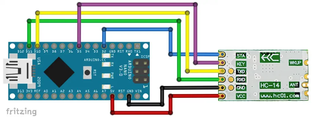
As the Nano only has one hardware serial port, I decided to use SoftwareSerial and selected pins 10 and 11 for this.
In this configuration, we control the KEY pin via software by setting PIN 5 to INPUT/LOW (KEY is HIGH due to its internal pull-up) or OUTPUT/LOW (KEY is LOW). Alternatively, you could connect KEY to GND via a switch. If you do not want to change the settings, you can also leave the pin unconnected.
We will use the STA pin later to wake up the microcontroller or to query the status of the HC-14 module. You can also leave it unconnected until then. Or you can attach an LED to it to visually monitor the status. A series resistor is already present internally.
Configuring the HC-14 module
Switching the HC-14 module to setting mode
To put the HC-14 module into setting mode, the KEY pin must be pulled LOW. There are 2 possibilities for this:
- KEY to LOW after the HC-14 module has been connected to the power supply.
- In this case, the set baud rate is used.
- KEY to LOW while or before the HC-14 module is connected to the power supply.
- In this case, the baud rate 9600 is used temporarily.
- Firmware V1.0: Changed settings are permanently retained.
- From firmware V1.1: Changed settings are lost after disconnection from the power supply.
Method 2 is helpful if you have forgotten which baud rate you have set in the HC-14 module.
The setting sketch
To set up the HC-14 module, upload the following sketch:
#include <SoftwareSerial.h>
const int keyPin = 5;

SoftwareSerial hc14(10,11); // RX, TX

void setup() {
  Serial.begin(9600);
  hc14.begin(9600);
  pinMode(keyPin, OUTPUT); // Setting Mode, change to INPUT for normal mode
  hc14.print("AT+RX");
  Serial.println("Current Settings of the HC-14 module: ");
  while(!hc14.available()){} // wait for HC-14 to answer
  Serial.println(hc14.readString());
  Serial.println("Now, enter your settings. Choose \"No Line Ending\" in the IDE!");
}

void loop() {
  if (hc14.available()) {
    Serial.write(hc14.read());
  }
  if (Serial.available()) {
    hc14.write(Serial.read());
  }
}
Here is the output:

We will discuss what this means in detail soon.
AT commands
The HC-14 module is set using AT commands. You can enter the commands via the serial monitor or as part of your code. Incidentally, AT commands were developed by the modem manufacturer Hayes in the early 1980s. “AT” stands for “come to ATtention”. When sending the AT commands, it is important that you have set “No line ending” in the Arduino IDE.
1. Connection test
Type “AT” (without the quotation marks) as a message into the serial monitor and press Enter. You should receive an “OK” in response.
2. Setting the default parameters
To reset the module to the default settings, use the following AT command:
Input: AT+DEFAULT
Response: OK+DEFAULT
3. Setting or querying the baud rate
You set the baud rate with :
AT+Bxxxx with xxxx = 1200, 2400, 4800, 9600, 19200, 38400, 57600 or 115200. The default setting is 9600.
Example:
Input: AT+B19200
Output: OK+B:19200
You query the baud rate with AT+B?.
4. Setting or querying the channel
You have a choice of 50 different frequencies (channels):
AT+Cxxx – where xxx is the channel according to the table below.
Example:
Input to set channel 28: AT+C028
Output: OK+C:28
You must always enter three characters for the channel by preceding one or two zeros.
Query: AT+C?
Here is the table with the different channels:

5. Setting the receiver sensitivity
The higher the receiver sensitivity, the greater the range, but the lower the transmission rate over the air.
The following table shows how long it takes to transmit a certain number of bytes. If the packet size specific to the receiver sensitivity is exceeded, the additional bytes are divided into packets accordingly.
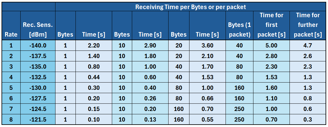
You set the receiver sensitivity as follows:
AT+Sx with x = rate
Example:
Input: AT+S3
Output: OK+S:3
Query: AT+S?
6. Querying the firmware version
You can query the firmware version as follows:
Input: AT+V?
Output: www.hc01.com HC-14V1.1 2022.12.12 → Version 1.1 from 12th Dec., 2022
7. Setting or querying the transmitter power
This is how you set the transmitter power:
AT+Pxx where x = power in dBm, integer values between 6 and 20 are allowed.
Example:
Input: AT+P20
Output: OK+P:+20dBm
Query: AT+P?
The transmission power can only be set from firmware V1.1!
8. Querying the most important settings
I have already explained how to query the baud rate, the channel, the receiver sensitivity and the transmitter power in one go (including the output) in the settings sketch above.
Query: AT+RX
Sending and receiving
Connecting two HC-14 modules
Now we come to the actual core of the article, namely sending and receiving data by radio. This is surprisingly simple. Duplicate the circuit from above and upload the following sketch to both microcontrollers. If you are using the Arduino IDE 2.x, it is best to rename the sketch for one of the microcontrollers so that you have two serial monitors available.
To be able to read the messages better, you should select the option “New Line” or “Both NL & CR”.
It is important that you have set the same receiver sensitivity and the same channel for both HC-14 modules.
#include <SoftwareSerial.h>
int keyPin = 5;

SoftwareSerial hc14(10,11); // RX, TX

void setup() {
  Serial.begin(9600);
  hc14.begin(9600);
  /* Uncomment the following lines if you want to check the settings
  pinMode(keyPin, OUTPUT); // Setting Mode, change to INPUT for normal mode
  hc14.print("AT+RX");
  Serial.println("Current Settings of the HC-14 module: ");
  while(!hc14.available()){} // wait for HC-14 to answer
  Serial.println(hc14.readString());
  Serial.println("Changing to normal mode - Enter your messages"); */
  pinMode(keyPin, INPUT);
}

void loop() {
  if (hc14.available()) {
    Serial.write(hc14.read());
  }
  if (Serial.available()) {
    hc14.write(Serial.read());
  }
}
If you now enter a message on one serial monitor, it will be output on the other and vice versa. It appears as if the two microcontrollers are connected directly via SoftwareSerial. This also offers you access to the numerous convenient serial functions described in my last article.
If you send a message that is larger than the packet size, you will see that the packets arrive with a time delay.
Connect more than two HC-14 modules
If you have more than two microcontrollers communicating with each other via HC-14 modules, a transmitted message will be received by all HC-14 modules that are set to the same channel and receiver sensitivity. You could use these settings to address modules individually. Unfortunately, the HC-14 modules do not offer individual addressing, as is the case with the fixed transmission mode of the Ebyte LoRa modules (see here). That is the price of simplicity.
Sending and receiving structures
In practical use, you may have to send data records that consist of different data types. Once again, I am using the example of a weather station to which the humidity (an integer), the temperature (a float) and the rain status (a bool) are to be transmitted. A structure as a data container is ideal for this.
Here is the transmitter sketch:
#include <SoftwareSerial.h>
#define INTERVAL 5000
unsigned long lastMillis = 0;
const int keyPin = 5;
struct weatherData {
int humidity;
float temperature;
bool rain;
};
weatherData currentWeather = { 32, 25.0, false };
SoftwareSerial hc14(10,11);
void setup() {
pinMode(keyPin, INPUT);
Serial.begin(9600);
hc14.begin(9600);
}
void loop() {
if( millis()-lastMillis >= INTERVAL ){
lastMillis = millis();
hc14.write((byte*)¤tWeather, sizeof(currentWeather));
Serial.println("Data sent");
}
}
And here is the receiver sketch:
#include <SoftwareSerial.h>
#define INTERVAL 5000
unsigned long lastMillis = 0;
int keyPin = 5;
struct weatherData {
int humidity;
float temperature;
bool rain;
};
weatherData currentWeather = { 0, 0.0, false };
SoftwareSerial hc14(10,11);
void setup() {
pinMode(keyPin, INPUT);
Serial.begin(9600);
hc14.begin(9600);
}
void loop() { // run over and over
if(hc14.available()){
hc14.readBytes((byte*)¤tWeather, sizeof(currentWeather));
Serial.print("Humidity [%]: ");
Serial.println(currentWeather.humidity);
Serial.print("Temperature [°C]: ");
Serial.println(currentWeather.temperature, 1);
if(currentWeather.rain){
Serial.println("It's raining.");
}
else{
Serial.println("It doesn't rain.");
}
Serial.println();
}
}
Since we are leaving the actual topic a bit here, I would just like to point out one aspect, namely that the structure is sent like this
hc14.write((byte*)¤tWeather, sizeof(currentWeather));
and with:
hc14.readBytes((byte*)¤tWeather, sizeof(currentWeather));
which is maybe not obvious, at least for beginners.
Saving power
Current is a precious resource for battery-powered projects. At least if you only communicate in one direction, as with the weather station, there are options for reducing power consumption.
Waking up the receiving microcontroller
The power-saving options on the receiver side are limited in that the HC-14 module must remain ready to receive and consumes around 20 mA of current. Unfortunately, it does not have a sleep mode from which it can be woken up by an incoming message. The Ebyte LoRa modules (and others) definitely do this better.
But at least you can send the microcontroller to sleep and use the STA signal from the HC-14 to wake it up again. When the HC-14 module receives data, STA goes LOW. This happens some time before the data is transmitted to the microcontroller via the TX pin of the HC-14 module. The delay depends on the transmission rate, which you set indirectly via the receiver sensitivity:

Whether this time is sufficient for the microcontroller to be ready to receive messages depends on the microcontroller and the sleep mode. I have successfully tested the following examples in S3 mode.
Example 1: AVR based Arduino board
I tried out the first example on an Arduino Nano. The Nano is put into power-down mode, from which it is woken up by an external interrupt (details on the sleep modes can be found here). The STA signal serves as the interrupt trigger. The incoming message is read with Serial.readStringUntil('\n'); to avoid a timeout. To do this, it is necessary to send the message on the sender side with Serial.println(), i.e. with a line feed. Or, you can select the setting “New Line” or “Both NL & CR” when sending via serial monitor. You can find out more about Serial here.
The receiver sketch:
#include <avr/sleep.h>
#include <SoftwareSerial.h>
const int keyPin = 5;
const int intPin = 2;

SoftwareSerial hc14(10,11);

void wakeUpISR() {
  delay(0); // add code if you want
}

void setup() {
  pinMode(keyPin, INPUT);
  pinMode(intPin, INPUT);
  attachInterrupt(digitalPinToInterrupt(intPin), wakeUpISR, FALLING);
  Serial.begin(9600);
  hc14.begin(9600);
  Serial.println("I am going to sleep now...");
  Serial.flush(); // without flush() the output might not be fully displayed
  set_sleep_mode(SLEEP_MODE_PWR_DOWN); // define sleep mode
  sleep_mode();  // now sleep
}

void loop() {
  if(hc14.available()){
    String messageIn = hc14.readStringUntil('\n');
    Serial.println(messageIn);
    Serial.println("I am going to sleep again...");
    Serial.flush();
    sleep_mode();
  }
}
An Arduino Nano consumes quite a lot of power even in power-down mode. The board LED, the USB-to-TTL chip and the voltage regulator are to blame. A better choice would be the Arduino Pro Mini or a “naked” AVR chip.
Example 2: ESP32 Development Board
We put the ESP32 into deep sleep mode. In contrast to the last example, the wake-up triggers a reset.
As no SoftwareSerial is implemented for the ESP32, we use Serial1 for communication with the HC-14.
This circuit was used:

And here is the corresponding sketch:
const int rx1Pin = 18;
const int tx1Pin = 19;
const int keyPin = 22;

void setup() {
  pinMode(keyPin, INPUT);
  Serial.begin(9600);
  delay(500);
  Serial1.begin(9600, SERIAL_8N1, rx1Pin, tx1Pin); // using Serial1 since the ESP32 has no SoftwareSerial
  esp_sleep_enable_ext0_wakeup(GPIO_NUM_33, LOW); // wake up by low Signal at GPIO 33
}

void loop() {
  if(Serial1.available()){
    String messageIn = Serial1.readStringUntil('\n');
    Serial.println(messageIn);
    Serial.println("I am going to sleep again...");
    Serial.flush();
    esp_deep_sleep_start();
  }
}
For this sketch, the outgoing message should also be terminated with a new line character on the sender side.
Saving more power – waking up the transmitting microcontroller
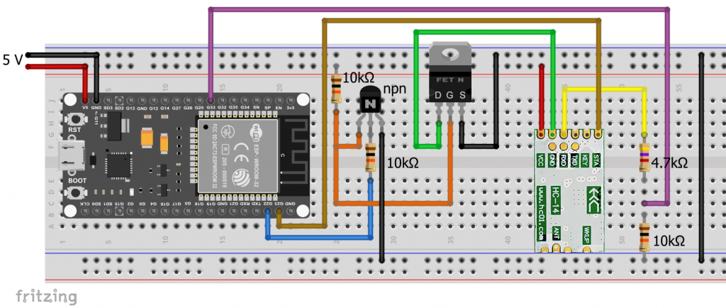
We can save power more effectively on the transmitting side by sending the microcontroller to sleep and waking it up regularly. We connect the power supply of the HC-14 module via a MOSFET. I show this here using the example of an ATtiny85. I have moved how you proceed with the ESP32 to the appendix, as the explanations have become relatively lengthy.
We use the watchdog timer for waking up, as this is the only time-controlled wake-up method for power-down mode.
The following circuit was used:

It is important that the gate-source threshold voltage VGS(th) of the MOSFET (i.e. the gate voltage at which it starts to conduct) is not too high. Search for “logic level MOSFETs”. The MOSFET must also be able to withstand the maximum expected current (ID = Continuous Drain Current). This worked for me using a BS170. Its maximum VGS(th) is 3 volts.
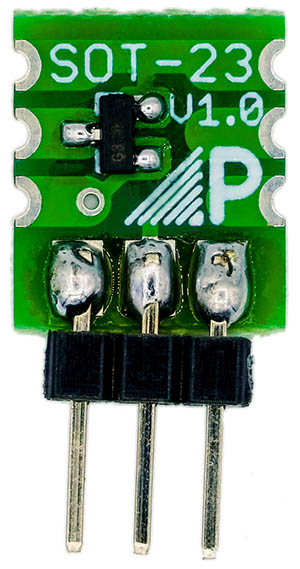
It is better to use a MOSFET with an even smaller VGS(th), such as the IRLML6244 (max. VGS(th) = 1.1 volts) or the IRLML2502 (max. VGS(th) = 1.2 volts). I have successfully tested both. However, they are only available in the SOT-23 design, which is why you have to solder them to an adapter board for breadboard experiments (see example on the right).
Program sequence
Here is the sketch:
#include<SoftwareSerial.h>
#include <avr/wdt.h>
#include <avr/sleep.h>
volatile int wdCounts = 0;
const int rxPin = 3;
const int txPin = 4;
const int staPin = 1;
const int hc14EnablePin = 2;

SoftwareSerial hc14(3,4);

void setup() {
  pinMode(hc14EnablePin, OUTPUT);
  digitalWrite(hc14EnablePin, HIGH);
  hc14.begin(9600);
  delay(500);
  watchdogSetup();
  set_sleep_mode(SLEEP_MODE_PWR_DOWN);
  hc14.println("ATtiny85 has started");
}

void loop() {
  if(wdCounts >= 2){ // send only every second wake up
    digitalWrite(hc14EnablePin, HIGH);
    delay(1000); // give HC14 time to get ready
    while(!digitalRead(staPin)){} // ensure HC14 is ready to receive commands
    hc14.println("Greetings from ATtiny85!");
    while(digitalRead(staPin)){} // wait for sending procedure
    while(!digitalRead(staPin)){} // wait until message is sent
    digitalWrite(hc14EnablePin, LOW);
    wdCounts = 0;
  }
  sleep_mode();
}

void watchdogSetup(void){
  cli();
  wdt_reset();
  WDTCR |= (1<<WDCE) | (1<<WDE);
  WDTCR |= (1<<WDIE) | (1<<WDE) | (1<<WDP3) | (1<<WDP0);  // Watchdog every 8s
  sei();
}

ISR(WDT_vect){
  wdCounts++;
  WDTCR |= (1<<WDIE); // avoid system reset
}
First, we include the required libraries, define the relevant pins and set a watchdog timer to the maximum of eight seconds. Since eight seconds is not a particularly long time, we introduce the counter wdCounts, with which we can control after how many times a message is sent (here: 2). The short wake times without sending a message are hardly significant in terms of energy consumption.
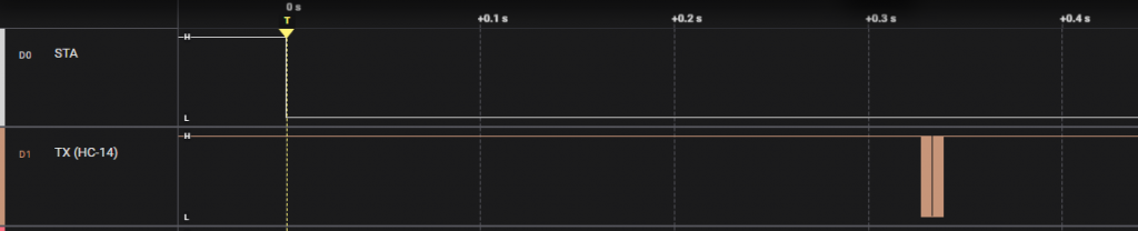
When it is time to send a message, the ATtiny85 “switches” the MOSFET so that the HC-14 is supplied with power. We give it one second to start up (this can be optimized if necessary). The further time sequence is controlled via STA. This is how the STA signal relates to the RX pin of the HC-14:

You can see how the message is received via the RX pin of the HC-14 module. The transmission process then begins, while STA goes LOW. When STA is HIGH again, we switch off the power to the HC-14 module and send the ATtiny85 to sleep.
With this setup, the power consumption during sleep time was 0.31 milliamps. This brings us into areas that allow continuous battery operation.
Range test for the HC-14 module
The range test was extremely pleasing. I carried it out with the highest receiver sensitivity (S1), the highest transmitter power (P20) and using 433 MHz stand antennas. The transmitter and receiver were controlled via an Arduino Nano. The transmitter was supplied with power from the PC via USB and was located in my study. The power supply for the receiver was a 9 volt lithium battery connected to VIN of the Arduino Nano.
The transmitter sent the message “Hello Receiver” every ten seconds. The following sketch was used on the receiver side:
#include <SoftwareSerial.h>
const int ledPin = 13;

SoftwareSerial hc14(10,11);

void setup() {
  pinMode(ledPin, OUTPUT);
  hc14.begin(9600);
}

void loop() {
  if(hc14.available()) {
    String messageIn = hc14.readString();
    if(messageIn == "Hello Receiver!"){
      for(int i=0; i<10; i++){
        digitalWrite(ledPin,!digitalRead(ledPin));
        delay(50);
      }
    }
  }
}
If the message is received correctly, the board LED flashes five times. I then walked across the fields with the receiver and determined the range. Apart from a temporary dead spot in the form of a dip, I still had reception for almost 3 kilometers, even though the transmitter was positioned inside my house and a few houses were in the way for the first meters:

Firmware V1.0 vs. Firmware V1.1
Firmware V1.0 dates from September 22, firmware 1.1 from December 22. I cannot say with certainty whether the external features guarantee identification of the firmware in every case, but my experience and that of several readers speaks in favor of this.

From my point of view, the most important differences are:
- V1.0 modules transmit at -20 dBm and cannot be down-regulated.
- The STA pin seems to have no function with the V1.0 modules. In my case, the STA pin was consistently LOW.
- Some AT commands are slightly different. If something does not work, try with and without the question mark.
- At least one reader of this article had transmission problems with the V1.0 version.
And, very important: In my experience, mixing module versions does not work.
Appendix – Saving power with the ESP32
Using a MOSFET
In principle, we can save power with the ESP32 using a MOSFET in the same way as before with the ATtiny85. However, due to the lower voltage of the ESP32, the circuit did not work with the BS170. Its maximum VGS(th) is too close to the 3.3 volts of the ESP32. However, the circuit worked with the IRLML6244 and the IRLML2502.

And here is the sketch:
const int unsigned long microSecToSec = 1000000;
const int sleepTime = 10; // in seconds
const int rx1Pin = 18; // dummy
const int tx1Pin = 33;
const int hc14EnablePin = 22;
const int staPin = 23;

void setup() {
  pinMode(hc14EnablePin, OUTPUT);
  digitalWrite(hc14EnablePin, HIGH);
  delay(1000); // give HC14 time to get ready
  Serial1.begin(9600, SERIAL_8N1, rx1Pin, tx1Pin);
  while(!digitalRead(staPin)){} // ensure HC14 is ready to receive commands
  Serial1.println("Hi, I just woke up! But I am tired again and will sleep for 10 seconds...");
  while(digitalRead(staPin)){} // wait for sending procedure
  while(!digitalRead(staPin)){} // wait until message is sent
  digitalWrite(hc14EnablePin, LOW);
  esp_sleep_enable_timer_wakeup(sleepTime * microSecToSec);
  esp_deep_sleep_start();
}

void loop() { }
The power supply was 5 volts at the 5 volt pin (usually referred to as VCC, VIN or V5). Disillusioned, I still noticed a power consumption of 10.9 mA in deep sleep mode. The problem is that many ESP32 boards are not optimized for power saving in deep sleep mode. Too many components on the board draw power. Removing the board LED only saved 1.5 mA. The solution is: get an optimized ESP32 board, such as the Adafruit ESP32 Feather V2 or the FireBeetle.
Using a MOSFET and a transistor
Variant 1: N-channel MOSFET
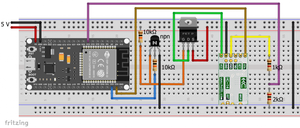
I am not sure whether the HC-14 module achieves the same range using the 3.3 volt power supply of the ESP32 as when connected to 5 volts. The voltage dipped below 3 volts when transmitting. I therefore tried another circuit based on 5 volts, which also worked with a BS170 or a 2N7000 MOSFET due to the higher voltage:
However, there are a few things to bear in mind here:
- As the RX pin of the HC-14 module is at 5 volts, we need a voltage divider or level shifter.
- The internal pull-up resistor of the RX pin of the HC-14 module is permanently supplied with voltage. As a result, a permanent current flows through the voltage divider. That’s why I chose relatively high resistance values.
- The transistor reverses the logic. If pin 22 (
hcEnablePin) is LOW, the transistor is closed and the voltage level at the gate of the MOSFET is HIGH. Accordingly, PIN 22 must be set to HIGH level during the sleep phase.
Here’s the sketch:
const int unsigned long microSecToSec = 1000000;
const int sleepTime = 10;
const int rx1Pin = 18; // dummy
const int tx1Pin = 33;
const int hc14EnablePin = 22;
const int staPin = 23;

void setup() {
  gpio_hold_dis(GPIO_NUM_22);
  pinMode(hc14EnablePin, OUTPUT);
  digitalWrite(hc14EnablePin, LOW);
  delay(1000);
  Serial1.begin(9600, SERIAL_8N1, rx1Pin, tx1Pin);
  while(!digitalRead(staPin)){} // ensure HC14 is ready to receive commands
  Serial1.println("Hi, I just woke up! But I am tired again and will sleep for 10 seconds...");
  while(digitalRead(staPin)){} // wait for sending procedure
  while(!digitalRead(staPin)){} // wait until message is sent
  digitalWrite(hc14EnablePin, HIGH);
  gpio_hold_en(GPIO_NUM_22); // hold GPIO 22 HIGH during deep sleep
  esp_sleep_enable_timer_wakeup(sleepTime * microSecToSec);
  gpio_deep_sleep_hold_en();
  esp_deep_sleep_start();
}

void loop() { }
Variant 2: P-channel MOSFET
The variant with P-channel MOSFET is somewhat more advantageous because the pull-up resistor of the RX pin of the HC-14 module is not supplied with power during the sleep phase. In addition, you do not need to keep pin 22 at HIGH level during the sleep phase.
The sketch is:
const int unsigned long microSecToSec = 1000000;
const int sleepTime = 10;
const int rx1Pin = 18; // dummy
const int tx1Pin = 33;
const int hc14EnablePin = 22;
const int staPin = 23;

void setup() {
  pinMode(hc14EnablePin, OUTPUT);
  digitalWrite(hc14EnablePin, HIGH);
  delay(1000);
  Serial1.begin(9600, SERIAL_8N1, rx1Pin, tx1Pin);
  while(!digitalRead(staPin)){} // ensure HC14 is ready to receive commands
  Serial1.println("Hi, I just woke up! But I am tired again and will sleep for 10 seconds...");
  while(digitalRead(staPin)){} // wait for sending procedure
  while(!digitalRead(staPin)){} // wait until message is sent
  digitalWrite(hc14EnablePin, LOW);
  esp_sleep_enable_timer_wakeup(sleepTime * microSecToSec);
  esp_deep_sleep_start();
}

void loop() { }
Moin Wolle,
Danke für den HC 14 Beitrag.
Ich möchte gerne einen Ir lesekopf für Stromzähler mittels 2 HC15 auf einen Wemis D1 übertragen. Meine Idee ist, rx rx vom Lesekopf auf RxTx HC15 verbinden Daten laufen mit 9600 baud, die dann zum 2. Hc15 übertragen werden und dann dort dann die RxTx von HC15 auf den WemosD1 auf die entsprechenden Gpio Pins gegeben werden.
wenn beide Hc15 Default Settings benutzen könnte das ohne Arduino Sketches funktionieren.
Mein Lesekops ist von Bitsheke und WemosD1 rennt mit Tasmota
Gruß aus dem hohen Norden
Volker
Moin Volker,
Kommentare auf Deutsch sollten besser bei der deutschen Version des Artikels veröffentlicht werden. Ich gehe davon aus, die Frage ist, ob dein Vorhaben funktioniert? Meine vage Antwort lautet: Könnte sein. Sendet der Stromzähler in hoher Frequenz und im Dauerfeuer? Dann kommt die Übertragung damit evtl. nicht klar. Ich würde sagen: probiere es aus. Wichtig wäre noch, dass neben der Baudrate auch die anderen Einstellungen (Stopp-/Paritätsbits) für Serial bei deinem Lesekopf, den HC-15 Modulen und dem Wemos Board übereinstimmen. Als Erstes würde ich probieren, ob die direkte Verbindung IR Leskopf zu Wemos Boards funktioniert. Wenn das klappt, dann sind die Chancen gut. Das Wemos Board und die HC-15 laufen auf 3.3 Volt. Du solltest also noch schauen, auf wieviel Volt der Serial-Ausgang des IR Lesekopfes läuft und ggf. Spannungsteiler oder einen Levelshifter einbauen.
Würde mich interessieren, ob es klappt!
VG, Wolfgang
Thanks for a really good article on this relative new radio board!
For what I understand there is a HC-15 now – quite similar to HC-14:
https://www.aliexpress.com/item/1005008299245748.html
Not sure what the difference is.
Thanks for this hint! I have found the datasheets for two different firmware versions and translated them from Chinese to English and German (using an AI-translator).
You find the results here.
At first glance, I could not see huge differences to the HC-14. I have ordered some modules from AliExpress and will test them.