About this post
In one of my first posts I had already reported on 433 MHz radio modules, but omitted the HC-12 module. I would like to close this gap now, especially since the HC-12 module has some very positive properties. On the one hand, it is characterized by simple operation, and on the other hand, it can be used both as a transmitter and a receiver.
The article is structured as follows:
- Technical characteristics
- Quick start
- How to make settings
- Range test
- Transmission of sensor data
Basics / Technical Properties
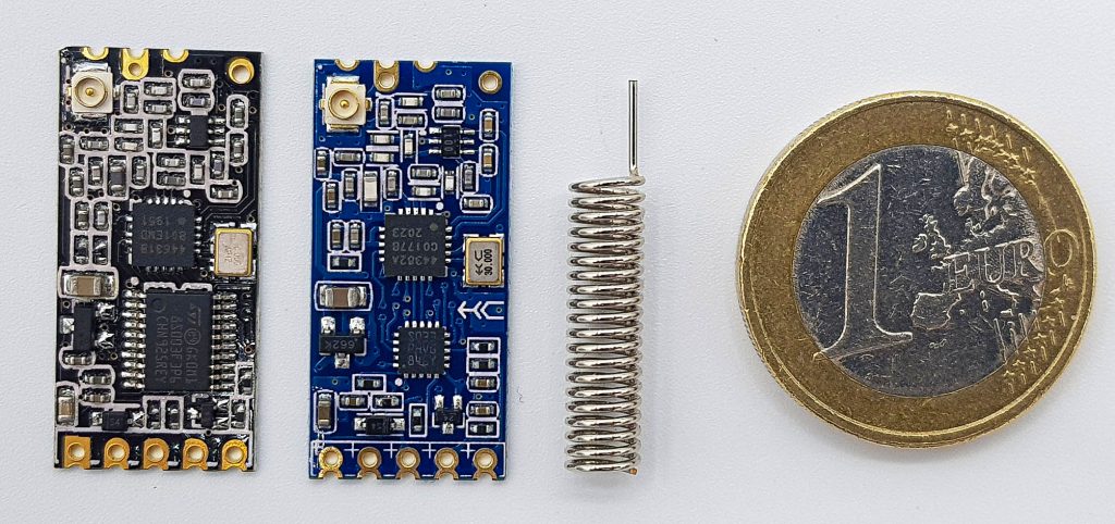
The HC-12 radio module is available in online shops for 6 to 9 euros. In Chinese shops it is again much cheaper, but you have to accept a few weeks delivery time there. Normally, a spiral antenna is supplied.
The module design varies. Some modules are based on the SI4463 transceiver, others on the SI4438. The former has a slightly longer range (more details here). The connections appear to be the same for all HC-12 modules. I was able to combine modules with SI4463 and SI4438 transceivers, but others report problems. To be on the safe side, try to work with a single type.
In advance: not everything the HC-12 module can do in terms of frequencies and ranges is allowed (in Germany – please check for your country). So don’t rejoice too soon. I will come back to that later.
Here is the most important data at a glance:
- Frequency range: 433.4 – 473.0 MHz
- Power consumption:
- non-sending: depending on operating mode 80 µA – 16 mA
- when sending: ~100 mA
- Sleep Mode: 23 µA (own measurement)
- Power supply: 3.2 – 5.5 volts
- Communication with the module: serial (RX / TX)
- Baudrate: 1200 – 115200
- Voltage Level: 3.3 volts/li>
- Range: maximum 1800 m
- maximum transmitting power: 20 dBm / 100 mW
- Transmission rate (radio): up to 250000 bps
- Settings via AT commands (SET Pin)
An essential feature of the HC-12 module is that it has its own microcontroller, which takes care of the radio transmission. You only contact the module via the serial connection. As you will see, the handling of the modules is therefore surprisingly easy. You don’t have to deal with any radio library.
Quick Start
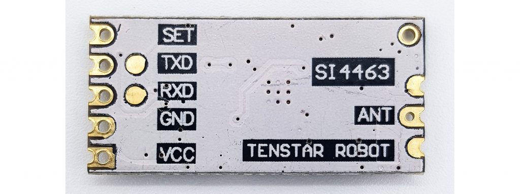
Wiring
Solder the spiral antenna to the module and connect it to the microcontroller or Arduino of your choice. At Arduino Nano it could look like this:

The base sketch
As an introduction, we take the modified SoftwareSerial sketch from the examples of the Arduino IDE. We choose 9600 Baud, because this is the default setting of the HC-12.
#include <SoftwareSerial.h>
SoftwareSerial hc12(10,11);

void setup() {
  Serial.begin(9600);
  hc12.begin(9600);
  Serial.println("Let's start!");
}

void loop() {
  if (hc12.available()) {
    Serial.write(hc12.read());
  }
  if (Serial.available()) {
    hc12.write(Serial.read());
  }
}
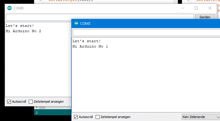
Upload the sketch on the first Arduino, then you open a second instance of the Arduino IDE (so just open the Arduino IDE again without closing the first one). Select the port of the second Arduino and upload the sketch to the second Arduino as well. Now you can open a serial monitor for each of them. Then write a message in one of the input fields, click on “Send” and the message appears in the serial monitor of the other Arduino.
It’s that simple! The only problem is that if you live in Germany, you have just violated the legal regulations for the use of the 433 MHz frequency band. These set 10 mW as the maximum permissible transmitting power. However, the HC-12 module transmits at 100 mW in the default settings. We’ll get to see how you can select the permissible range. If you want to know more about the rules for radio use (in Germany), then I recommend this link to an easy-to-understand summary.
Settings of the HC-12 radio module
The settings are made via AT commands, which you may already know from the Bluetooth modules HC-05 and HC-06. To enter AT mode, all you have to do is connect SET to GND. Alternatively, you connect SET to an I/O pin and set it to OUTPUT and LOW. The SET pin is internally connected with a 10 kOhm pull-up resistor. If you disconnect it from GND again or switch the I/O pin to INPUT, it returns into normal radio mode. It takes about 40 milliseconds to do this.
It makes a difference whether you pull down SET to LOW during operation or already when the module is switched on:
- Switching during operation: the module remains accessible with the settings selected for the serial connection (baud rate, data bits, parity bit, stop bit).
- Connecting SET to GND when switching on: The baud rate for communication with the module is set to 9600 baud. Also: 8 data bits, no parity, one stop bit.
The latter method is handy if you forgot which baud rate you set on the module. Otherwise you would simply have to try it out.
Put the HC-12 module into AT mode as a first test. For the Arduino you continue to use the HC12_SoftwareSerial Sketch from above. Type in “AT” (without the quotation marks) into the input field. The module should kindly respond with “OK”.
Setting the baud rate
The following table shows which baud rates you can set for communication with the HC-12 module. The radio baud rate (“Baud Rate in the Air”) is automatically adjusted by the module.
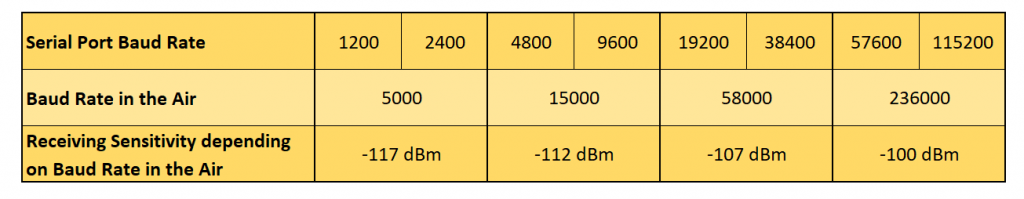
You pay for a high data rate with a low reception sensitivity. With each reduction of 6 dBm, the sensitivity is reduced to half.
The transmitting and the receiving module must have set the same baud rate. The setting is done with:
- AT+Bx with x = 1200, 2400, 4800, etc.
The setting is always active only when you have left AT mode.
Setting the radio mode
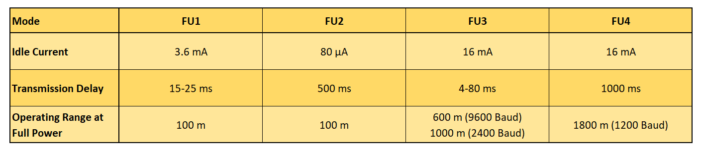
The HC-12 module has the four radio modes: FU1, FU2, FU3 (default) and FU4:
You set the radio mode as follows:
- AT+FUx with x = 1, 2, 3 or 4
Radio mode FU1
FU1 is a moderate power saving mode. The HC-12 module consumes 3.6 mA (I measured 3.8 mA) as long as it does not send. You can apply all baud rates in this mode, but the radio baud rate (“in the air”) is set to 250000 bps. Thus, you have a high data rate, but only a limited range. I think a range of 100 m as stated in the data sheet is very optimistic. In addition, the range is even shorter if you reduce the transmission power to the level permitted in Germany.
If you instruct the module to send something, it will do so with some delay. In FU1 mode, the delay is between 15 and 25 ms.
Radio mode FU2
FU2 mode is an extreme power saving mode. According to the data sheet, the consumption drops to 80 µA. I measured even less, the consumption periodically fluctuated between 23 and 80 µA. Apparently, the module goes intermittent into sleep mode. Only 1200, 2400 or 4800 are allowed baud rates. The radio baud rate is again very high at 250000 bps and the range is accordingly limited. The delay is 500 ms.
If you switch from another mode to FU2 and a higher baud rate was set, then the baud rate is reduced to 4800. If, on the other hand, you set FU2 mode and then select a baud rate greater than 4800, your transmission will no longer work.
Radio mode FU3
FU3 is the default mode. You can select all baud rates. The radio baud rate is set automatically according to Table 1. The power consumption is quite high at 16 mA. According to the data sheet, 1000 m range can be achieved (with illegal 100 mW transmitting power). Depending on the baud rate, the delay is between 4 and 80 ms.
Radio mode FU4
This mode is designed to achieve long ranges of up to 1800 meters. The only allowed baud rate is 1200. The radio baud rate is even reduced to 500 bps. The data packages should not exceed 60 bytes and there should be a pause of 2 seconds between sending two packages.
Setting the transmitting power
Now we come to the setting of the transmitting power. The HC-12 module offers eight power levels:
As you can easily see, the legal limit (for Germany) is between Level 4 and Level 5. The setting is done as follows:
- AT+Px with x = 1, 2, 3, 4, 5, 6, 7, 8
The default is 8.
Setting the channel
A nice feature of the HC-12 module is the possibility to set 100 channels, each with a frequency shifted by 400 kHz. Channel 001 uses the frequency 433.4 MHz, channel 100 uses 473.0 MHz. Unfortunately, there is again a problem here (at least in Germany) because the permissible frequency range is between 433.05 and 434.79. Thus, only channels 1 to 4 are allowed (and again: if you are in Germany).
The channels are set with:
- AT+Cx with x = 001, 002, 003 …. 099, 100
The default is channel 001.
Setting the data format
In serial data transfer, you can set the number of bits that are transmitted per byte. Anything other than 8 would be exotic. It is followed by a parity bit – or none (non parity). If a parity bit sent, you can choose whether to check for even or odd parity. Finally, either 1, 2 or 1.5 stop bits are transmitted.
The data format is set as follows:
- AT+Uxyz with:
- x = number of bits, i.e. normally 8
- y = O (odd parity check), E (even parity check), N (no parity check)
- z = 1 (one stop bit), 2 (2 stop bits), 3 (1.5 stop bits)
The default is: 8N1.
Other settings
- AT+SLEEP puts the module into sleep mode. It will only need 23 µA. The sleep mode starts when you leave the AT mode. The module is awakened by entering AT mode for a short time. An example sketch of this can be found below.
- AT+DEFAULT resets all settings.
- AT+UPDATE puts the module in a state that allows uploading a new firmware.
Querying the HC-12 module
You can not only make settings, but also query them:
- AT+V delivers the firmware version
- AT+Rx, with
- x = B, C, F or P for baud rate, channel, radio mode or transmitting power
- x = X means that all parameters are queried
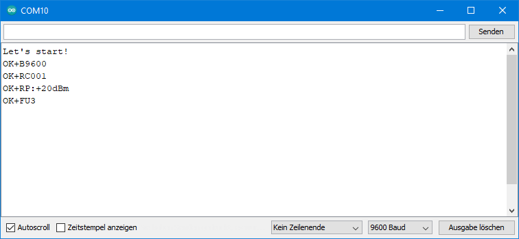
This is what the answer to “AT+RX” looks like:
Using the sleep mode
The sleep mode is particularly suitable for modules that are only to send something from time to time, such as the data of a weather station. In principle, I have already explained above how it works. It is important that delays are added in some places.
The sample sketch has the HC-12 module send a friendly “Hello again” every 10 seconds and then sends it to sleep.
#include <SoftwareSerial.h>
SoftwareSerial hc12(10,11);
int SETPin = 5;

void setup() {
  pinMode(SETPin,INPUT);
  Serial.begin(9600);
  hc12.begin(9600);
  Serial.println("Let's start!");
}

void loop() {
  hc12.print("Hello again");
  delay(100);

  pinMode(SETPin, OUTPUT);
  delay(50);
  hc12.print("AT+SLEEP");
  delay(50);
  pinMode(SETPin, INPUT);

  delay(10000);

  pinMode(SETPin, OUTPUT);
  delay(100);
  pinMode(SETPin, INPUT);
  delay(100);
}
Range test
To test the range of the module, I first used the setup shown above. I operated the two Arduino Nano Boards with 9 volt batteries. The transmitting unit ran with the following simple sketch, which I probably don’t have to explain:
#include <SoftwareSerial.h>
SoftwareSerial hc12(10,11);

void setup() {
  hc12.begin(9600);
}

void loop() {
  hc12.print("Hi Wolle");
  delay(3000);
}
On the receiver side I attached an LED to pin 6 of the Arduino Nano. The recipient sketch checks to see if a message has been sent. If this is the case, it checks to see if the message is correct. If so, the LED lights up for half a second. I moved away from the transmitter with the receiver until the LED stopped blinking or stopped blinking regularly. I did the experiment in an open field with direct visual contact.
#include <SoftwareSerial.h>
SoftwareSerial hc12(10,11);
int ledPin = 6;

void setup() {
  hc12.begin(9600);
  pinMode(ledPin, OUTPUT);
}

void loop() {
  String message = "";
  if(hc12.available()) {
    message = hc12.readString();
    if(message=="Hi Wolle"){
      digitalWrite(ledPin, HIGH);
      delay(500);
      digitalWrite(ledPin, LOW);
    }
  }
}
With the standard settings (FU3 / 9600 Baud / 100 mW transmitting power) and the spiral antenna I could bridge a distance of approx. 120 meters. This is only a fraction of the 600 meters indicated above.
Improving the range
Two hardware changes can increase the range:
- Attach a big capacitor to the power supply. The data sheet recommends 1000 µF. I had only 470 F in my stock. The capacitor ensures that the sudden, high power can be supplied when sending.
- Use a better antenna. From previous experiments I know that a 17.3 cm (= 1/4 of the wavelength) long straight wire already lead to higher ranges than the spiral antennas.
But now I wanted to go all the way and got two external 433 MHz antennas for about 15 euros each. Since they had SMA connectors, I had to get two SMA-to-IPEX adapters. Here’s what the setup looked like:

As a schematic:

With this I achieved a range of more than 1000 meters. In the end, the limiting factor was the free view from module to module. So I cannot say with certainty whether 1800 meters are actually reachable.
It was only then that I realized that the transmission power I used was not permitted in Germany. I then did further tests with the allowed powerlevel 4). Using the spiral antenna in FU3 mode, the range dropped less than I feared to 80 meters. Due to the change to FU4 it went up again to 180 meters. And with the good antenna, I could achieve 350 meters.
I also tested the modules with the SI4438 chip and could not find any difference to the SI4463 based modules. However, I only tried one parameter set.
Here is a summary of all test results:

In my house I could easily send messages through two walls and a ceiling using FU3 / 9600 Baud / Spiral Antenna / Powerlevel 4.
Check what you really need and play around a bit. Do not overdo it with the transmitting power. After all, you also wouldn’t want your 433 MHz applications to be disrupted by transmitters of your neighbors!
Transmission of sensor data
Finally, for the less experienced, a guide on how to transfer sensor data. More specifically, it’s about how you build strings from integers and floats, send them, and convert them back on the receiver side.
The transmitter providing the data (server) converts the data using String(Zahl) into strings that are linked together, but separated by non-numbers (asterisks in this example). If the transmitting unit receives a request, the string is sent. The sketch sends fixed values. You would replace that with sensor data or something similar.
#include <SoftwareSerial.h>
SoftwareSerial hc12(10,11);

void setup() {
  Serial.begin(9600);
  Serial.println("Let's start!");
  hc12.begin(9600);
}

void loop() {
  String requestString = "";
  if (hc12.available()) {
    requestString = hc12.readString();
    Serial.println(requestString);
  }
  if(requestString == "request"){
    String dataString = "";
    createDataString(dataString);
    Serial.println(dataString);
    hc12.print(dataString);
  }
}

void createDataString(String &data){
  int sensor1 = 746;
  int sensor2 = 8295;
  float sensor3 = 41.84;
  data = "*" + String(sensor1) + "*" + String(sensor2) + "*" + String(sensor3);
}
On the receiver side (client) I have installed a button that triggers the request.

After a short time, the client receives the response from the server. To extract the numbers from the incoming string, there are the very useful functions parseInt() and parseFloat(). These functions analyze the incoming characters. They wait until digits occur, collect them until the next non-digit (except for the decimal point at parseFloat()), and convert these numbers into an integer or float value.
#include <SoftwareSerial.h>
SoftwareSerial hc12(10,11);
int requestPin = 7;

void setup() {
  pinMode(requestPin, INPUT);
  Serial.begin(9600);
  hc12.begin(9600);
  Serial.println("Let's start!");
}

void loop() {
  int sensorData1 = 0;
  int sensorData2 = 0;
  float sensorData3 = 0.0;

  if (hc12.available()){
    sensorData1 = hc12.parseInt();
    sensorData2 = hc12.parseInt();
    sensorData3 = hc12.parseFloat();

    Serial.print("Sensor 1: ");
    Serial.println(sensorData1);
    Serial.print("Sensor 2: ");
    Serial.println(sensorData2);
    Serial.print("Sensor 3: ");
    Serial.println(sensorData3);
  }
  if(digitalRead(requestPin)) {
    delay(300); // debounce
    hc12.print("request");
  }
}
Here’s what the output looks like on the transmitter and the receiver side:
Acknowledgement
The two males on the post picture are from Peggy and Marco Lachmann-Anke. I owe the paragraph symbol to Michael Schwarzenberger. Everything as usual from Pixabay.
The HC-12 module as Fritzing component was created by Estevéo Trabbold (stvz) on fritzing.org.
Dear Wolfgang,
I use a HC12 in Firmware v2.6.
In “AT” mode I set FU1 and queries like AT+RX do work. BAud rate is 9600 in the serial link to the hc12.
If I change to FU4 and I need to set hc12.begin(1200) to get readable characters back, I still have communication but not all queries are properly answered.
AT –> “OK”
AT+V –> works
AT+RX –> only “OK”
AT+RC –> “Error” (same for AT+RB) etc.
Hi Sebastian, I have a module with firmware v2.6. If I go to FU4 and HC-12 BAUD = 9600, I don’t get errors, but only letters that make no sense. If I set Serial also to BAUD 1200 with Serial.begin(1200), then everything works fine. Do you want to try?
voltage devider on both tx:rx makes no sense at all
it is only for 5v -> 3v
3v is 5v ttl compatible
Thanks, stupid error
can i also use an nokia 5110 as a disply to data log with this device for voltage and current.
I have no idea how one would connect HC-12 with a phone.
Hi Wolfgang
The Nokia 5110 is an LCD display and not a Phone and yes it can be used to display most types of data. I just thought you might like to know.
cheers Jeff Donegal
Hi Jeff,
if you google “nokia 5110” you will see the good old phone. If you google “nokia 5110 display” you indeed find the displays. That confused me. Thanks. I have meanwhile ordered such displays but not yet managed to try them.
Found this:
https://www.az-delivery.de/products/lcd-display-84×48-pixel-kostenfreies-e-book
An ebook which you can order for free. Also available in English and costs 0$.
But don’t know how good it is.
I think I will dive a bit into these displays since I like the retro-style.
Best wishes, Wolfgang
Hi Wolfgang
My apologies, I did not know that there was a phone called the 5110. I am well up on the display but never knew there was a phone with the same number. You will find out as you get into the displays that they are not all that bright nor do they give a very clear display. On line you can find many projects using this display but I regard them as a last resort display. There are many colour LCDs that produce fantastic displays and are just as easy to use and in some cases are cheaper than the 5110. Still they are a quick and easy way to interface with us humans. A warning. be carefull as they are easily damaged and do not like voltages more than about 3.5v. I managed to destroy a few of them while designing a project using them.
I wish you well in your quest to understand these little critters. Also WELL DONE on your efforts with the HC12 Bluetooth modules. I am about to embark on a project that will use these units. I knew little about them before but your project taught me a lot. Thankyou for that.
All the best. Jeff.
Hi Jeff, thanks for sharing your experience with these devices! Best wishes, Wolfgang
can the set pin connected to other pins or only on d5?
You can take any I/O Pin you like. Just try!
Hi Wolfgang,
Thank you for the pointer, that does make sense. I will try that and will get back with you with the result.
Regards,
Givi
Thank you for your instructions on HC-12. However, I only receive multiple reverse “?” on each T/R from on each Nano’s serial Monitor. I tried and set different matching Baud rates, however, no change. I set everything the same on each HC-12 “OK+ U8N1, OK+B9600, OK+RC077, OK+RP:+20dBm, OK+FU4”. Please let me know .
Thanks and regards,
Givi
Hi Givi, if you see these strange signs on the serial monitor, then usually the Baud rate of your device is not aligned with the Baud rate of you serial monitor. It seems you have applied 9600 for the HC-12. Do you have the same setting on the serial monitor?
Regards, Wolfgang
Hi Wolfgang,
Thank you for getting back with me on this. I loaded the Arduino sketch that you showed in your article and as you see in my previous notes the setting on both HC-12 are the same and “9600” baud selected.
I don’t know if I can attach anything here for you to see.
Thanks.
Givi
Which sketch di you upload? This one: HC12_SoftwareSerial.ino ? Don’t you even see the “Let’s start” at the beginning? And have you left the setting mode (SET unconnected or connected to HIGH Level)?
And if you want to send something, then, please to my e-mail address: wolfgang.ewald@wolles-elektronikkiste.de .
Hi Givi, you have connected the SET pin to D5. Disconnect it or set D5 to HIGH. Then I think it will work. I also have connected it the circuit I have published but in the text I say that the SET Pin is not needed at this stage. This might be confusing. When the SET pin is connected to LOW level then the module is in the setting mode.
Wolfgang
Hi Wolfgang,
I added digitalWrite(5, HIGH); and loaded the sketch, but no change. I am still getting multiple “⸮” each time I send text. However, I measured the voltage on pin 10 and pin 11 and they were at 5V. Is that what it should be?
Thanks,
Givi
Hi Givi,
yes, that’s normal for SoftwareSerial. The lines are HIGH, and signals are LOW. Same as for I2C.
But maybe now I have found the issue. You have chosen FU4 and in that mode only a baud rate of 1200 is allowed. The module changes (at least mine does it) to baud 1200 automatically. If my modules are at baud 9600 for example and I enter “AT+FU4”, the module’s answer is “OK+FU4,B1200”.
Maybe you have a different firmware (“AT+V”). My modules have “www.hc01.com HC-12 v2.6”.
Doesn’t matter. So, either your modules do not change automatically into baud 1200 for FU4 or they don’t tell. You can try two things: 1) Force them into baud 1200 2) try setting your SoftwareSerial baud rate to 1200.
In order to see if your modules work correctly at all, you can also set them back to default (“AT+DEFAULT”) and choose 9600 as baud rate.
Hope this will solve the issue.
Good luck, Wolfgang
Hi Wolfgang,
Thank you for the pointer, that does make sense. I will try that and will get back with you with the result.
Regards,
Givi
Hi Wolfgang,
After Setting to default “AT+DEFAULT” the issue went away and it worked. So, the problem is the “AT+FUx” setting and increasing the bit rate/Baud rate needs a lower “FUx”.
Also, my Firmware version is the same “www.hc01.com HC-12 v2.6”. Is there a new one and where can we download it from.
Vielen Dank für deine Hilfe.
Givi
Dear Wolfgang;
Would you know if this module already has internal error control protocols in the same way as Bluetooth modules?
Data is sent in packets (as internet) that are only decoded after an crc check and and ack. If package is not well received it is sent again. This is transparent to the user, guaranteeing virtually error-free communication.
Hi Antonio, I haven’t found any hint in the (poor) HC12 datasheets or in the datasheet of the underlying SI4463 / SI 4438. So, I assume there is no check. If you want to be sure that the data was transmitted correctly, you might let the receiver the message back to compare, or you also send the number of characters of your message and / or a parity bit.