About this Post
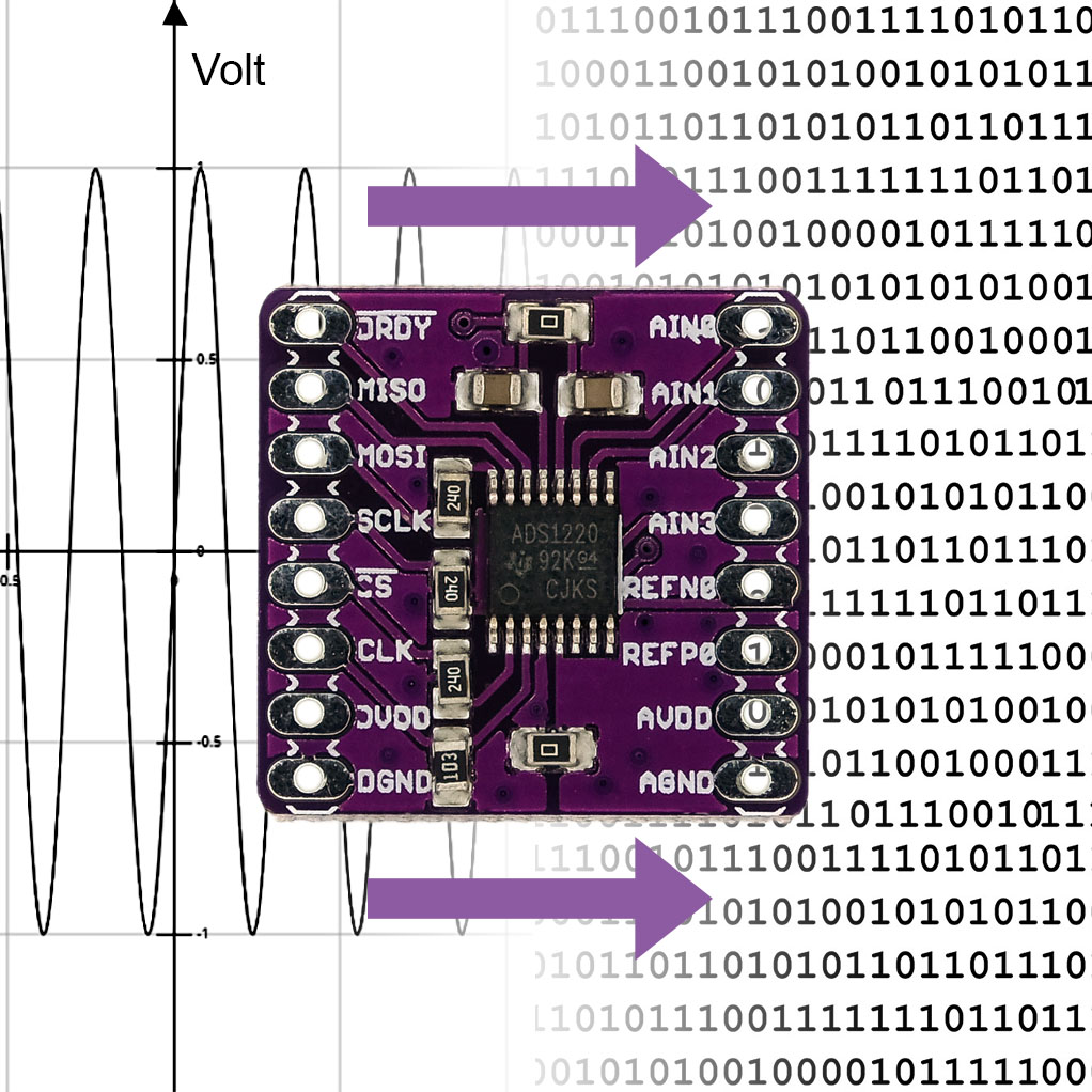
Many applications require precise measurement of voltages. With the internal A/D converters (ADCs) of the Arduino, ESP8266 or ESP32 boards, you will quickly reach the limits. You can achieve good results with the 16-bit A/D converter ADS1115, which I reported about here. But even 16 bits are sometimes not enough, e.g. when controlling load cells (see my posts about HX711 based scales or strain gauges). In this article, I will introduce the (comparatively) easy-to-use 24-bit ADC ADS1220.
As part of my research, I tried the Protocentral_ADS1220 library. It is slim and basically it works well, except for one of the two example ketches. However, when testing various settings, I often had to refer to the ADS1220 data sheet or look for the parameters for the functions in the header file. Therefore, I have written the library ADS1220_WE. It is an attempt to make the operation of the ADS1220 comfortable. You can find my library here on GitHub or install it using the Arduino library manager. Try both and choose the one you like best.
Technical data of the ADS1220
IC vs. module
For the connection of the ADS1220 to a microcontroller, the data sheet in section 9.1.1 recommends the use of some capacitors and resistors. If you want it simple, like I do, use a module that already has these additional components implemented. You can get such a module in online stores for less than 10 Euros, mostly directly from China.
Essential data at a glance
Key technical data are:
- Analog power supply: 2.3 to 5.5 volts at AVDD / AVSS (AGND).
- Digital power supply: 2.3 to 5.5 volts at DVDD / DGND.
- Bipolar power supply option: e.g. AVSS to DGND = -2.5 volts, AVDD to DGND = +2.5 volts.
- Power consumption: 120 microamps in duty cycle mode.
- Communication: via SPI.
- Reference voltages:
- Internal: 2.048 volts.
- External: VREFPx – VREFNx = min. 0.75 volts, max. AVDD.
- Gain: 1 – 128 (with PGA = Programmable Gain Amplifier), 1 – 4 (without PGA).
- Data rate: 5 – 2000 SPS (Samples per Second)
- Conversion modes: Continuous and “Single-Shot” mode.
- Voltage inputs: 4 single-ended (against AVSS) or 2 differential inputs.
- Measurement in multiplex mode.
- Two programmable IDACs (digital-to-analog converter for current): 10 microamps to 1.5 milliamperes (also called “excitation current source” in the data sheet).
- Digital filter: 50 and/or 60 Hz.
- Integrated temperature sensor.
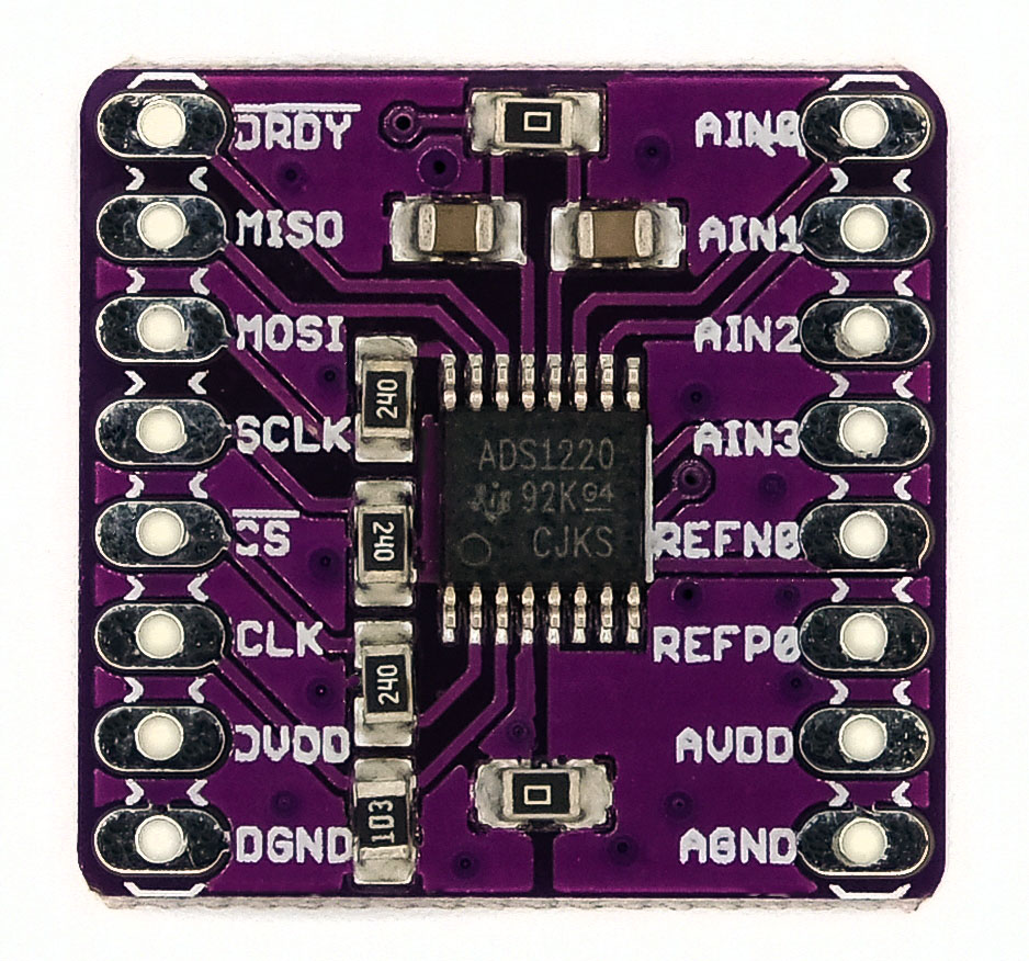
Pinout of the ADS1220 (module)
The labels of the inputs and outputs on the module partly differ from the data sheet (in brackets, if different):
- MISO (DOUT/DRDY), MOSI (DIN), SCLK, CS: SPI – connectors
- AVDD, AGND (AVSS): Analog voltage supply
- DVDD, DGND: Digital voltage
- CLK: external clock (optional)
- DRDY: Data Ready Pin, is LOW when data is available.
- REFP0, REFN0: external reference voltage; “P” = positive, “N” = negative.
- AIN0 (AIN0/REFP1), AIN1, AIN2, AIN3 (AIN3/REFN1): Inputs for the voltages to be measured.
- AIN0/AIN3 can alternatively be used as input for an additional external reference voltage.
Simple measurements
Basic Circuit
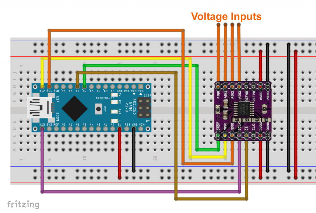
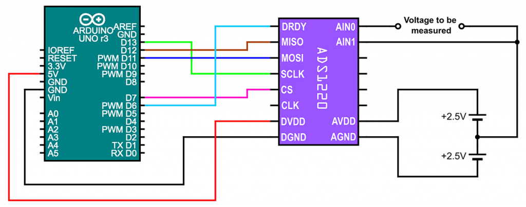
I will explain how to use the ADS1220 with example sketches. First, I want to show you how to change input channels and query data using the default settings. For my example sketch, the following circuit was used:
Best pratice circuits
The manufacturer of the ADS1220 recommends using 47 Ω resistors between all digital inputs and outputs and the microcontroller. It also recommends using 0.1 F capacitors between AVDD and GND and between DVDD and GND. CLK should be connected to GND. You can find more detailed information on this in section 9.1.1 of the data sheet.
The ADS1220 modules I have do have 24 Ω resistors in front of MOSI, CS, and SCLK. Why this size? I don’t know. Theoretically, you would need to add 23 Ω resistors there and install 47 Ω resistors on MISO and DRDY. Capacitors are obviously located on AVDD and DVDD, but I don’t know if they have the recommended capacity. CLK is connected to DGND via a 10 kΩ resistor. So you don’t need to worry about that.
Unused analogue inputs/outputs should be connected to AVDD or (AVDD+AVSS)/2. Exception: AIN3/REFN1. Unused digital inputs should be connected to DVDD or DGND. Exceptions: CLK – DGND only; DRDY – leave unconnected or HIGH via pull-up resistor.
If you need different voltages for DGND/DVDD and AGND/AVDD
The module I used has two 0 Ω resistors that connect DGND and AGND or DVDD and AVDD. In this respect, I could have saved two connections above. If you need different voltages for the digital and analog pins, then remove at least the resistor that connects DVDD to AVDD, and possibly also the second one (e.g. with a bipolar power supply).

A few notes beforehand
In this example, the internal voltage reference of 2.048 volts is used. This means that you can only measure voltages in the range of -2.048 to +2.048 volts.
The output voltage of the PGA must be greater than AVSS plus 200 millivolts and lower than AVDD minus 200 millivolts. Outside these limits, the ADS1220 no longer operates linearly. As the standard gain is 1, these limits also apply to the input voltage in the first example. To be on the safe side, we turn off the PGA with bypassPGA(true).
The measured voltage is calculated from the raw value as follows, taking into account the amplification factor and the reference voltage:
![\[ \text{voltage} = \frac{\text{rawValue}\cdot \text{referenceVoltage}}{2^{23}\cdot \text{gainFactor}}\;\text{[V]} \]](https://wolles-elektronikkiste.de/wp-content/ql-cache/quicklatex.com-299bee013ad4fc930ddb01171aa0c5fd_l3.png "Rendered by QuickLaTeX.com")
The sketch
Here’s the sketch:
#include <ADS1220_WE.h>
#include <SPI.h>

#define ADS1220_CS_PIN    7 // chip select pin
#define ADS1220_DRDY_PIN  6 // data ready pin

/* Create your ADS1220 object */
ADS1220_WE ads = ADS1220_WE(ADS1220_CS_PIN, ADS1220_DRDY_PIN);
/* Alternatively you can also pass the SPI object as reference */
// ADS1220_WE ads = ADS1220_WE(&SPI, ADS1220_CS_PIN, ADS1220_DRDY_PIN);

void setup(){
  Serial.begin(9600);
  if(!ads.init()){
    Serial.println("ADS1220 is not connected!");
    while(1);
  }
/* The voltages to be measured need to be between negative VREF + 0.2 V and positive
 * VREF -0.2 V if PGA is enabled. For this basic example I disable PGA, to be on the
 * safe side.
 */
  ads.bypassPGA(true);
}

/*
 *  You set the channels to be measured with setCompareChannels(); You
 * can choose the following parameters:
 * Parameter                  Pos. Input     Neg. Input         Comment
 * ADS1220_MUX_0_1              AIN0           AIN1
 * ADS1220_MUX_0_2              AIN0           AIN2
 * ADS1220_MUX_0_3              AIN0           AIN3
 * ADS1220_MUX_1_2              AIN1           AIN2
 * ADS1220_MUX_1_3              AIN1           AIN3
 * ADS1220_MUX_2_3              AIN2           AIN3
 * ADS1220_MUX_1_0              AIN1           AIN0
 * ADS1220_MUX_3_2              AIN3           AIN2
 * ADS1220_MUX_0_AVSS           AIN0           AVSS           single-ended
 * ADS1220_MUX_1_AVSS           AIN1           AVSS           single-ended
 * ADS1220_MUX_2_AVSS           AIN2           AVSS           single-ended
 * ADS1220_MUX_3_AVSS           AIN3           AVSS           single-ended
 * ADS1220_MUX_REFPX_REFNX_4   REFP0/REFP1   REFN0/REFN1     (REFPX-REFNX)/4; PGA bypassed
 * ADS1220_MUX_AVDD_M_AVSS_4    AVDD           AVSS           (AVDD-AVSS)/4; PGA bypassed
 * ADS1220_MUX_AVDD_P_AVSS_2  (AVDD+AVSS)/2 (AVDD+AVSS)/2     for self tests
 *
 * The last three modes use the internal reference (2.048 V) and gain = 1, independent of
 * your settings.
 */


void loop(){
  float result = 0.0;
  long longResult = 0;

  ads.setCompareChannels(ADS1220_MUX_0_1);
  result = ads.getVoltage_mV();
  longResult = ads.getRawData();
  Serial.print("AIN0 vs. AIN1  [mV]: ");
  Serial.println(result);
  Serial.print("AIN0 vs. AIN1 (raw): ");  // raw data
  Serial.println(longResult);

  ads.setCompareChannels(ADS1220_MUX_0_AVSS);
  result = ads.getVoltage_mV();
  Serial.print("AIN0 vs. AVSS  [mV]: ");
  Serial.println(result);

  ads.setCompareChannels(ADS1220_MUX_1_AVSS);
  result = ads.getVoltage_mV();
  Serial.print("AIN1 vs. AVSS  [mV]: ");
  Serial.println(result);

  ads.setCompareChannels(ADS1220_MUX_2_AVSS);
  result = ads.getVoltage_muV();    // request result in microvolts
  Serial.print("AIN2 vs. AVSS  [µV]: ");
  Serial.println(result);

  ads.setCompareChannels(ADS1220_MUX_3_AVSS);
  result = ads.getVoltage_mV();
  Serial.print("AIN3 vs. AVSS  [mV]: ");
  Serial.println(result);

  ads.setCompareChannels(ADS1220_MUX_AVDD_M_AVSS_4); // voltage supply / 4
  result = ads.getVoltage_mV() * 4.0;
  Serial.print("Supply Voltage [mV]: ");
  Serial.println(result);

  result = ads.getVRef_V();                 // get the reference voltage
  Serial.print("Reference       [V]: ");
  Serial.println(result,3);

  Serial.print("Temperature    [°C]: ");    // get the temperature
  result = ads.getTemperature();
  Serial.println(result);

  Serial.println();

  delay(2000);
}
Explanations to the sketch
I only go into the parts that, I think, need explanation (otherwise, ask!):
- With
init()you initialize the ADS1220. Among other things, the function performs a reset. setCompareChannels()defines which inputs are used for the measurement.- The parameter
ADS1220_MUX_REFPX_REFNX_4causes the reference voltage REFP0/REFN0 or REFP1/REFN1 to be measured. Regardless of your settings, this bypasses the PGA, the gain is 1, and the internal reference is used. To ensure that this also works with reference voltages greater than 2.048 volts, the voltage is reduced to a quarter before the measurement. - When using the parameter
ADS1220_MUX_AVDD_M_AVSS_4you measure a quarter of the supply voltage. ADS1220_MUX_AVDD_P_AVSS_2connects AINN and AINP to (AVDD+AGND)/2. Ideally, you will get 0 as a result. This allows you to determine offsets.- The functions
getVoltage_mV()/getVoltage_muV()provide the result in millivolts and microvolts. It is always waited until DRDY goes LOW. This ensures that you get a “fresh” result. In single-shot mode, the measurements must be initiated. The getVoltage functions take care of that as well. - Alternatively, query the raw value of the A/D conversion with
getRawData(). - With
getVRef_V()you get the reference voltage in volts. This is not the result of a measurement, but the function returns what you have set. The default setting is 2.048 volts. getTemperature()provides the temperature in degrees Celsius.
Output
This is how the output of the sketch may look like:

As you can see,VAIN0/AIN1 = (VAIN0/AVSS –VAIN1/AVSS), which must be the case on closer inspection.
Change of the reference voltage of the ADS1220
As mentioned before, you have four options for the reference voltage:
- Internal reference voltage (2.048 volts)
- External reference voltage at REFP0/REFN0
- External reference voltage at REFP1/REFN1 (at the expense of two voltage inputs)
- Supply voltage (AVDD/AVSS) as voltage reference
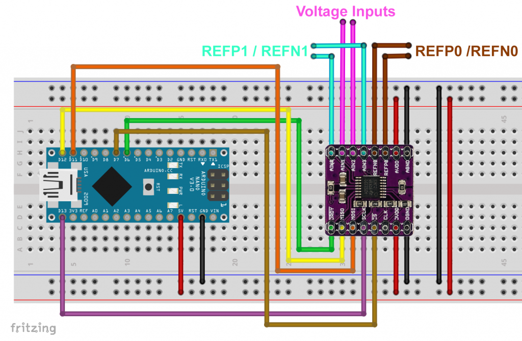
The following circuit diagram is intended to illustrate this:
An example sketch
I used the circuit shown above and applied different reference voltages to REFP0/REFN0 and REFP1/REFN1. A test voltage to be measured was connected to AIN2.
The following sketch shows how to set or change reference voltages for the ADS1220:
#include <ADS1220_WE.h>
#include <SPI.h>
#define ADS1220_CS_PIN 7 // chip select pin
#define ADS1220_DRDY_PIN 6 // data ready pin
/* Create your ADS1220 object */
ADS1220_WE ads = ADS1220_WE(ADS1220_CS_PIN, ADS1220_DRDY_PIN);
/* Alternatively you can also pass the SPI object as reference */
// ADS1220_WE ads = ADS1220_WE(&SPI, ADS1220_CS_PIN, ADS1220_DRDY_PIN);
void setup(){
Serial.begin(9600);
if(!ads.init()){
Serial.println("ADS1220 is not connected!");
while(1);
}
}
/* For better readability of the code the setting options are explained here and not
* in loop() where the functions are used.
*
* You set the channels to be measured with setCompareChannels(); You
* can choose the following parameters:
* Parameter Pos. Input Neg. Input Comment
* ADS1220_MUX_0_1 AIN0 AIN1
* ADS1220_MUX_0_2 AIN0 AIN2
* ADS1220_MUX_0_3 AIN0 AIN3
* ADS1220_MUX_1_2 AIN1 AIN2
* ADS1220_MUX_1_3 AIN1 AIN3
* ADS1220_MUX_2_3 AIN2 AIN3
* ADS1220_MUX_1_0 AIN1 AIN0
* ADS1220_MUX_3_2 AIN3 AIN2
* ADS1220_MUX_0_AVSS AIN0 AVSS (=AGND) single-ended
* ADS1220_MUX_1_AVSS AIN1 AVSS single-ended
* ADS1220_MUX_2_AVSS AIN2 AVSS single-ended
* ADS1220_MUX_3_AVSS AIN3 AVSS single-ended
* ADS1220_MUX_REFPX_REFNX_4 REFP0/REFP1 REFN0/REFN1 (REFPX-REFNX)/4; PGA bypassed
* ADS1220_MUX_AVDD_M_AVSS_4 AVDD AVSS (AVDD-AVSS)/4; PGA bypassed
* ADS1220_MUX_AVDD_P_AVSS_2 (AVDD+AVSS)/2 (AVDD+AVSS)/2 for self tests
* The last three modes use the internal reference (2.048 V) and gain = 1, independent of
* your settings.
*
* setVRefSource() sets the the reference voltage source. Parameters are:
* ADS1220_VREF_INT int. reference 2.048 V (default)
* ADS1220_VREF_REFP0_REFN0 ext. reference = Vrefp0 - Vrefn0
* ADS1220_VREF_REFP1_REFN1 ext. reference = Vrefp1 - Vrefn1 (REFP1=AIN0, REFN1=AIN3)
* ADS1220_VREF_AVDD_AVSS ext. reference = supply voltage
*
* If you use the above options you also have to set the value of vRef "manually":
* setVRefValue_V(vRef in volts);
*
* Alternatively, you can set the reference voltage source and let the ADS1220 measure
* the reference. Be aware that this is not a measurement with highest precision. "Calibration"
* might be a bit misleading. You should take the lowest data rate (default) for most accurate
* results. You can use the following functions:
* setRefp0Refn0AsVrefAndCalibrate();
* setRefp1Refn1AsVrefAndCalibrate();
* setAvddAvssAsVrefAndCalibrate();
* setIntVRef();
* The latter function sets the default settings.
*/
void loop(){
float result = 0.0;
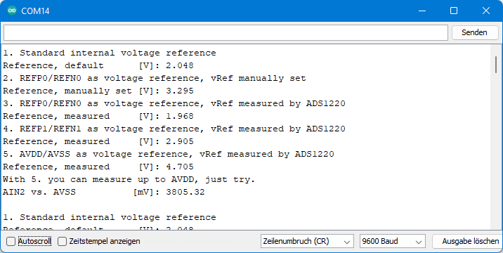
Serial.println("1. Standard internal voltage reference");
result = ads.getVRef_V(); // get the reference voltage
Serial.print("Reference, default [V]: ");
Serial.println(result,3);
Serial.println("2. REFP0/REFN0 as voltage reference, vRef manually set");
ads.setVRefSource(ADS1220_VREF_REFP0_REFN0);
ads.setVRefValue_V(3.295); // set reference voltage in volts
result = ads.getVRef_V();
Serial.print("Reference, manually set [V]: ");
Serial.println(result,3);
Serial.println("3. REFP0/REFN0 as voltage reference, vRef measured by ADS1220");
ads.setRefp0Refn0AsVrefAndCalibrate();
result = ads.getVRef_V();
Serial.print("Reference, measured [V]: ");
Serial.println(result,3);
Serial.println("4. REFP1/REFN1 as voltage reference, vRef measured by ADS1220");
ads.setRefp1Refn1AsVrefAndCalibrate();
result = ads.getVRef_V();
Serial.print("Reference, measured [V]: ");
Serial.println(result,3);
Serial.println("5. AVDD/AVSS as voltage reference, vRef measured by ADS1220");
ads.setAvddAvssAsVrefAndCalibrate();
result = ads.getVRef_V();
Serial.print("Reference, measured [V]: ");
Serial.println(result,3);
Serial.println("With 5. you can measure up to AVDD, just try.");
ads.setCompareChannels(ADS1220_MUX_2_AVSS);
result = ads.getVoltage_mV();
Serial.print("AIN2 vs. AVSS [mV]: ");
Serial.println(result);
ads.setIntVRef(); // switch back to standard vRef
Serial.println();
delay(2000);
}
The output
This is what the output looked like for me:
Explanations to the sketch
By default, the ADS1220 uses the internal reference voltage. If you want to switch to an external reference voltage, you have two options:
- You define the reference voltage source with
setVRefSource()and specify its value withsetVRefValue(). - With a single instruction you set the reference voltage source and let the ADS1220 measure the reference voltage value. The following functions are available for this purpose:
setRefp0Refn0AsVrefAndCalibrate(): REFP0/REFN0setRefp1Refn1AsVrefAndCalibrate(): REFP1/REFN1setAvddAvssAsVrefAndCalibrate():AVDD/AVSS
The ADS1220 data sheet states that the external reference measurement is less accurate than a regular measurement. One should not overestimate this error, because the internal reference voltage also has a certain error (up to 3 millivolts). However, I would not call the functions 2a-2c too often, because the reference value will then always fluctuate a little.
I applied a supply voltage (AVDD/AVSS) of about 5 volts and checked the voltage with my multimeter and via setAvddAvssAsVrefAndCalibrate() and getVRef_V(). The deviation was a maximum of one millivolt.
What’s the point of all these references?
In many applications, such as Wheatstone bridges or resistance thermometers, one is not interested in absolute voltage values, but rather in resistances determined via voltage ratios and reference resistances. By applying a current across the sought resistor and across the reference resistor, and using the voltage drop across the reference resistor as the reference voltage, the sought resistor can be determined independently of current variations. This will be the subject of my next post.
Setting PGA and Gain
The voltage to be converted can be amplified with the PGA (Programmable Gain Amplifier). Gain factors between 1 and 128 are available. As described earlier, you leave the linear range when the output voltage of the PGA approaches AVDD or AVSS to less than 200 millivolts. You can bypass this restriction by bypassing the PGA. Confusingly, you can still apply gains of 1, 2 or 4.
These are the functions:
setGain(): sets the gain factor (1, 2, 4, 8, 16, 32, 64 or 128).getGainFactor(): returns the actual gain factor as a byte value. The actual gain factor may differ from the value you set before (see below).bypassPGA(true/false): bypasses the PGA or switches it on again.isPGABypassed():returns true if the PGA is bypassed, false otherwise. Again, the value may differ from your preset.
There are still a few things to keep in mind:
- If you set a gain factor >= 8, the PGA will not be bypassed, and this is independent of your settings made with
bypassPGA(). - If you perform a single-ended measurement (AINx = AVSS), then the PGA must be bypassed and only gains of 1, 2 and 4 are possible. The library will ensure that these rules are followed. You don’t have to worry about it, but you should be aware of the limitation.
- The PGA is also forcibly bypassed when measuring external reference voltages or the supply voltage. The gain factor is reduced to 1.
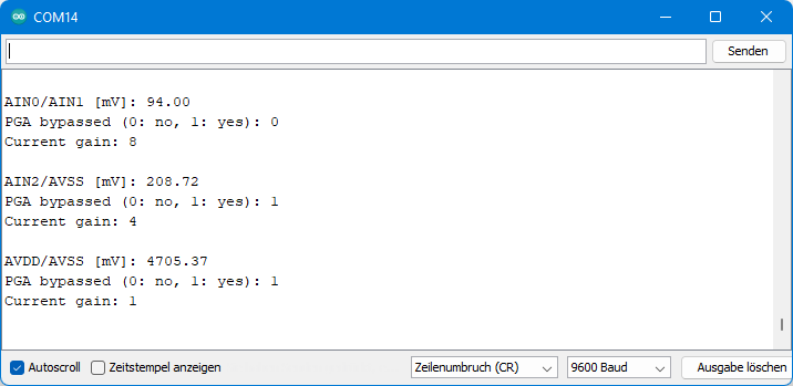
Example sketch
To illustrate how the PGA state and gain changes, I wrote the following sketch. As you can see, forced changes are made to the settings under certain conditions, but they are also undone when the conditions are changed back.
#include <ADS1220_WE.h>
#include <SPI.h>

#define ADS1220_CS_PIN    7
#define ADS1220_DRDY_PIN  6

ADS1220_WE ads = ADS1220_WE(ADS1220_CS_PIN, ADS1220_DRDY_PIN);

void setup(){
  Serial.begin(9600);
  ads.init();
  ads.setGain(ADS1220_GAIN_8); // set gain to 8
  ads.bypassPGA(false);  // redundant, since this is default, but I wanted to highlight this setting.
}

void loop(){
  ads.setCompareChannels(ADS1220_MUX_0_1);
  float result = ads.getVoltage_mV();
  byte gain = ads.getGainFactor();  // queries the (effective) gain
  Serial.print("AIN0/AIN1 [mV]: ");
  Serial.println(result);
  Serial.print("PGA bypassed (0: no, 1: yes): ");
  Serial.println(ads.isPGABypassed()); // queries if PGA is bypassed, here the result will be 0
  Serial.print("Current gain: ");  //

  Serial.println(gain);
  Serial.println();

  ads.setCompareChannels(ADS1220_MUX_2_AVSS);
  result = ads.getVoltage_mV();
  gain = ads.getGainFactor();
  Serial.print("AIN2/AVSS [mV]: ");
  Serial.println(result);
  Serial.print("PGA bypassed (0: no, 1: yes): "); // the PGA will be bypassed
  Serial.println(ads.isPGABypassed());
  Serial.print("Current gain: ");  // gain will be reduced to 4.
  Serial.println(gain);
  Serial.println();

  ads.setCompareChannels(ADS1220_MUX_AVDD_M_AVSS_4);
  result = ads.getVoltage_mV();
  gain = ads.getGainFactor();
  Serial.print("AVDD/AVSS [mV]: ");
  Serial.println(result*4.0);
  Serial.print("PGA bypassed (0: no, 1: yes): "); // the PGA will be bypassed
  Serial.println(ads.isPGABypassed());
  Serial.print("Current gain: ");  // gain will be reduced to 1.
  Serial.println(gain);
  Serial.println();

  delay(2000);
}
Here is the output:
IDAC settings
The ADS1220 allows you to set up constant currents between 10 microamps and 1.5 milliamps on two pins. These currents are referred to as IDAC1 and IDAC2. Since the current is known and the ADS1220 measures the voltage needed to generate the current, you can conveniently measure resistances this way. A typical application is temperature measurement with resistance thermometers.
I would like to demonstrate the function with a simple example. To do this, place a 10 kΩ resistor between AIN0 and AIN1 or between AIN2 and AIN1, respectively. Connect AIN1 to AVSS.

Then upload the following sketch:
#include <ADS1220_WE.h>
#include <SPI.h>

#define ADS1220_CS_PIN    7 // chip select pin
#define ADS1220_DRDY_PIN  6 // data ready pin

ADS1220_WE ads = ADS1220_WE(ADS1220_CS_PIN, ADS1220_DRDY_PIN);

void setup() {
  Serial.begin(9600);
  if (!ads.init()) {
    Serial.println("ADS1220 is not connected!");
    while (1);
  }
  //  ads.setCompareChannels(ADS1220_MUX_0_1); default seeting for this test
  ads.setGain(ADS1220_GAIN_1);
  ads.bypassPGA(true); // since the negative voltage is AVSS, we have to bypass PGA

  /* The ADS1220 can provide two excitation currents, IDAC1 and IDAC2. It takes up to 200µs
     until the current is set up. The library includes a delay, so you don't have to add one.
     You can switch IDAC1 and IDAC2 on and off individually but the current is the same for
     both.
     The ADS1220 will try to provide the voltage needed for the current you have chosen. This
     voltage shall not exceed AVDD - 0.9V.

     ADS1220_IDAC_OFF         // default
     ADS1220_IDAC_10_MU_A     // set IDAC1/IDAC2 to 10 µA
     ADS1220_IDAC_50_MU_A     // 50 µA
     ADS1220_IDAC_100_MU_A    // 100 µA
     ADS1220_IDAC_250_MU_A    // 250 µA
     ADS1220_IDAC_500_MU_A    // 500 µA
     ADS1220_IDAC_1000_MU_A   // 1000 µA
     ADS1220_IDAC_1500_MU_A   // 1500 µA
  */
 ads.setIdacCurrent(ADS1220_IDAC_100_MU_A);

  /* You can choose to which pin IDAC1 and IDAC2 are directed. The parameters are self-explaining.
     ADS1220_IDAC_NONE
     ADS1220_IDAC_AIN0_REFP1
     ADS1220_IDAC_AIN1
     ADS1220_IDAC_AIN2
     ADS1220_IDAC_AIN3_REFN1
     ADS1220_IDAC_REFP0
     ADS1220_IDAC_REFN0
  */
  //  ads.setIdac1Routing(ADS1220_IDAC_AIN0_REFP1);
  //  ads.setIdac2Routing(ADS1220_IDAC_AIN2);

} // end of setup()

void loop() {
  float result = 0.0;

  ads.setIdac1Routing(ADS1220_IDAC_AIN0_REFP1);
  result = ads.getVoltage_mV();
  Serial.print("Voltage, caused by IDAC1 [mV]:           ");
  Serial.println(result, 3);  // will be roughly 1000 mA, according to Ohm's law

  ads.setIdac2Routing(ADS1220_IDAC_AIN2);
  result = ads.getVoltage_mV();
  Serial.print("Voltage, caused by IDAC1 and IDAC2 [mV]: ");
  Serial.println(result, 3);  // will be roughly 2000 mA, according to Ohm's law

  ads.setIdac1Routing(ADS1220_IDAC_NONE);
  ads.setIdac2Routing(ADS1220_IDAC_NONE);
  Serial.println();

  delay(2000);
}
Output
Your output should look like this or similar:

Explanations
The handling of IDACs is simple:
setIdacCurrent(ADS1220_IDAC_100_MU_A);sets the current to the desired value, here it is 100 microamps. IDAC1 and IDAC2 are identical in terms of current level.setIdac1Routing(ADS1220_IDAC_AIN0_REFP1);sets pin AIN0/REFP1 as current source for IDAC1. For IDAC2 you proceed accordingly, if you want to apply two currents. Use the parameterADS1220_IDAC_NONEto turn off the power.
Then you simply measure the voltage at the current output pin and calculate the resistance. As you can see, you can also merge IDAC1 and IDAC2.
You have to take care that the current is only high enough for the ADS1220 to generate the necessary voltage. According to the data sheet, the IDAC voltage should not exceed AVDD minus 0.9 volts.
The IDACs have a typical deviation of one percent. So, this is not a precision measurement. It is better to use reference resistors (see next article).
Other settings of the ADS1220
The other settings of the ADS1220 have fewer “side effects”. I have therefore summarized them in a sketch and also included the functions already covered once again. This should be quite a convenient template for your own sketches. You just have to uncomment the corresponding functions and apply your parameters. The sketch is called ADS1220_WE_all_settings.ino and is, like the previous examples, part of the library.
The sketch
Here is the sketch:
#include <ADS1220_WE.h>
#include <SPI.h>

#define ADS1220_CS_PIN    7 // chip select pin
#define ADS1220_DRDY_PIN  6 // data ready pin

/* Create your ADS1220 object */
ADS1220_WE ads = ADS1220_WE(ADS1220_CS_PIN, ADS1220_DRDY_PIN);
/* Alternatively you can also pass the SPI object as reference */
// ADS1220_WE ads = ADS1220_WE(&SPI, ADS1220_CS_PIN, ADS1220_DRDY_PIN);

void setup() {
  Serial.begin(9600);
  if (!ads.init()) {
    Serial.println("ADS1220 is not connected!");
    while (1);
  }

  /* General settings / commands */
  //  ads.start(); // wake up from power down and start measurement
  //  ads.reset(); // resets the ADS1220; all settings will change to default
  //  ads.powerDown(); // send the ADS1220 to sleep
  //  ads.setSPIClockSpeed(8000000); // set SPI clock speed, default is 4 MHz

  /* You set the channels to be measured with setCompareChannels(); You
     can choose the following parameters:
     Parameter                  Pos. Input     Neg. Input         Comment
     ADS1220_MUX_0_1              AIN0           AIN1             default
     ADS1220_MUX_0_2              AIN0           AIN2
     ADS1220_MUX_0_3              AIN0           AIN3
     ADS1220_MUX_1_2              AIN1           AIN2
     ADS1220_MUX_1_3              AIN1           AIN3
     ADS1220_MUX_2_3              AIN2           AIN2
     ADS1220_MUX_1_0              AIN1           AIN0
     ADS1220_MUX_3_2              AIN3           AIN2
     ADS1220_MUX_0_AVSS           AIN0           AVSS (=AGND)   single-ended
     ADS1220_MUX_1_AVSS           AIN1           AVSS           single-ended
     ADS1220_MUX_2_AVSS           AIN2           AVSS           single-ended
     ADS1220_MUX_3_AVSS           AIN3           AVSS           single-ended
     ADS1220_MUX_REFPX_REFNX_4   REFP0/REFP1   REFN0/REFN1     (REFPX-REFNX)/4; PGA bypassed
     ADS1220_MUX_AVDD_M_AVSS_4    AVDD           AVSS          (AVDD-AVSS)/4; PGA bypassed
     ADS1220_MUX_AVDD_P_AVSS_2  (AVDD+AVSS)/2 (AVDD+AVSS)/2     for self tests
     The last three modes use the internal reference (2.048 V) and gain = 1, independent of
     your settings.
  */
  //  ads.setCompareChannels(ADS1220_MUX_0_3);

  /* You can choose a gain between 1 (default) and 128 using setGain() if PGA is enabled
     (default). If PGA is disabled you can still choose a gain factor up to 4. If PGA is
     enabled, the amplified voltage shall be between AVSS + 200mV and AVDD - 200mV. Outside
     this range linearity drops. For details check the data sheet, section 8.3.2.1.

     If you apply a single-ended mode (negative AINx = AVSS), PGA must be bypassed. Accordingly,
     the maximum gain is 4. The library does these settings automatically.

     For the measurement of reference voltages / supply voltage PGA will also be bypassed. In
     this case gain is 1.

     The parameters you can choose for setGain() are:
     ADS1220_GAIN_X with X = 1,2,4,8,16,32,64 or 128

     With getGainFactor() you can query the gain. The function returns the effective gain and
     not the gain set in the register. Under certian conditions thes are are different. For
     example, the effective gain is set to 1 when external references are measured.
  */
  ads.setGain(ADS1220_GAIN_1);
  //  ads.getGainFactor(); // returns the effective gain as a byte value
  //  ads.bypassPGA(true); // true disables PGA, false enables PGA
  //  ads.isPGABypassed(); // returns true, if PGA is bypassed

  /* The data rate level with setDataRate(). The data rate itself also depends on the operating
     mode and the clock. If the internal clock is used or an external clock with 4.096 MHz the data
     rates are as follows (per second):

      Level               Normal Mode      Duty-Cycle      Turbo Mode
     ADS1220_DR_LVL_0          20               5               40         (default)
     ADS1220_DR_LVL_1          45              11.25            90
     ADS1220_DR_LVL_2          90              22.5            180
     ADS1220_DR_LVL_3         175              44              350
     ADS1220_DR_LVL_4         330              82.5            660
     ADS1220_DR_LVL_5         600             150             1200
     ADS1220_DR_LVL_6        1000             250             2000

     The higher the data rate, the higher the noise (tables are provided in section 7.1 in the
     data sheet). In single-shot mode the conversion times equal the times in Normal Mode.
  */
  //  ads.setDataRate(ADS1220_DR_LVL_2);

  /* Using setOperatingMode() you choose the operating mode. Possible parameters are:
     ADS1220_NORMAL_MODE      ->  Normal Mode
     ADS1220_DUTY_CYCLE_MODE  ->  Duty cycle mode. Saves power, but noise is higher.
     ADS1220_TURBO_MODE       ->  Turbo Mode for fast measurements
  */
  //  ads.setOperatingMode(ADS1220_DUTY_CYCLE_MODE);

  /*  You can choose between a continuous and a single-shot (on demand) mode with
      setConversionMode(). Parameters are:
      ADS1220_SINGLE_SHOT (default)
      ADS1220_CONTINUOUS
  */
  // ads.setConversionMode(ADS1220_CONTINUOUS);

  /* In order to obtain temperature values, choose enableTemperatureSensor(true); false will
     disable the temperature sensor. As long as the temperature sensor is enabled the ADS1220
     is blocked for this task. To obtain voltage values, you have to switch the sensor off. The
     temperature is queried with getTemperature();
  */
  //  ads.enableTemperatureSensor(true);
  //  ads.getTemperature(); // returns temperature as float

  /*
     setVRefSource() sets the the reference voltage source. Parameters are:
     ADS1220_VREF_INT          int. reference 2.048 V (default)
     ADS1220_VREF_REFP0_REFN0  ext. reference = Vrefp0 - Vrefn0
     ADS1220_VREF_REFP1_REFN1  ext. reference = Vrefp1 - Vrefn1 (REFP1=AIN0, REFN1=AIN3)
     ADS1220_VREF_AVDD_AVSS    ext. reference = supply voltage

     If you use the above options you also have to set the value of vRef "manually":
     setVRefValue_V(vRef in volts);

     Alternatively, you can set the reference voltage source and let the ADS1220 measure
     the reference. Be aware that this is not a measurement with highest precision.
     "Calibration" might be a bit misleading. You should take the lowest data rate (default)
     for most accurate results. You can use the following functions:
     setRefp0Refn0AsVrefAndCalibrate();
     setRefp1Refn1AsVrefAndCalibrate();
     setAvddAvssAsVrefAndCalibrate();
     setIntVRef();
     The latter function sets the default settings.

     Be aware that VREFPx must be >= VREFNx + 0.75V.
  */
  //  ads.setVRefSource(ADS1220_VREF_REFP0_REFN0);
  //  ads.setVRefValue_V(3.312);  // just an example
  //  or:
  //  ads.setRefp0Refn0AsVrefAndCalibrate(); //or:
  //  ads.setRefp1Refn1AsVrefAndCalibrate(); //or:
  //  ads.setAvddAvssAsVrefAndCalibrate(); //or:
  //  ads.setIntVRef();
  //  to query VRef:
  //  ads.getVRef_V(); // returns VRef as float

  /* You can set a filter to reduce 50 and or 60 Hz noise with setFIRFilter(); Parameters:
     ADS1220_NONE       no filter (default)
     ADS1220_50HZ_60HZ  50Hz and 60Hz filter
     ADS1220_50HZ       50Hz filter
     ADS1220_60HZ       60Hz filter
  */
  //  ads.setFIRFilter(ADS1220_50HZ_60HZ);

  /* When data is ready the DRDY pin will turn from HIGH to LOW. In addition, also the DOUT pin
     can be set as a data ready pin. The function is setDrdyMode(), parameters are:
     ADS1220_DRDY        only DRDY pin is indicating data readiness  (default);
     ADS1220_DOUT_DRDY   DRDY and DOUT pin indicate data readiness
  */
  //  ads.setDrdyMode(ADS1220_DOUT_DRDY);


  /* There is a switch between AIN3/REFN1 and AVSS. You can use this option to save power in
     bridge sensor applications.
     ADS1220_ALWAYS_OPEN    The switch is always open.
     ADS1220_SWITCH         Switch automatically closes when the START/SYNC command is sent
                            and opens when the POWERDOWN command is issued.
  */
  // ads.setLowSidePowerSwitch(ADS1220_SWITCH);

  /* The ADS1220 can provide two excitation currents, IDAC1 and IDAC2. It takes up to 200µs
     until the current is set up. The library includes a delay, so you don't have to add one.
     You can switch IDAC1 and IDAC2 on and off individually but the current is the same for
     both.
     The ADS1220 will try to provide the voltage needed for the current you have chosen. This
     voltage shall not exceed AVDD - 0.9V.

     ADS1220_IDAC_OFF         // default
     ADS1220_IDAC_10_MU_A     // set IDAC1/IDAC2 to 10 µA
     ADS1220_IDAC_50_MU_A     // 50 µA
     ADS1220_IDAC_100_MU_A    // 100 µA
     ADS1220_IDAC_250_MU_A    // 250 µA
     ADS1220_IDAC_500_MU_A    // 500 µA
     ADS1220_IDAC_1000_MU_A   // 1000 µA
     ADS1220_IDAC_1500_MU_A   // 1500 µA
  */
  // ads.setIdacCurrent(ADS1220_IDAC_50_MU_A);

  /* You can choose to which pin IDAC1 and IDAC2 are directed. The parameters are self-explaining.
     ADS1220_IDAC_NONE
     ADS1220_IDAC_AIN0_REFP1
     ADS1220_IDAC_AIN1
     ADS1220_IDAC_AIN2
     ADS1220_IDAC_AIN3_REFN1
     ADS1220_IDAC_REFP0
     ADS1220_IDAC_REFN0
  */
  //  ads.setIdac1Routing(ADS1220_IDAC_AIN0_REFP1);
  //  ads.setIdac2Routing(ads1220IdacRouting route);

} // end of setup()

void loop() {
  float result = 0.0;

  /* The following functions query measured values from the ADS1220. If you request values in
     single-shot mode, the conversion will be initiated automatically. The value will be delivered
     once DRDY goes LOW. This ensures that you will receive "fresh" data. This is particularly
     important when you change channels.
  */
  result = ads.getVoltage_mV(); // get result in millivolts
  //  ads.getVoltage_muV(); // get result in microvolts
  //  ads.getRawData();  // get raw result (signed 24 bit as long int)
  //  ads.getTemperature();  // get temperature (you need to enable the T-sensor before);
  Serial.println(result, 3);

  delay(2000);
}
Explanations to the sketch and settings
General settings / functions
start(): wakes up the ADS1220 from power down mode. Moreover, the function starts single or continuous measurements. However, you don’t need it for this purpose, sincestart()is called automatically when you request readings.reset(): performs a reset of the ADS1220.powerDown(): sends the ADS1220 into power down mode. In this state, the current consumption drops to typically 0.1 microampere.setSPIClockSpeed(): sets the SPI clock frequency. Default setting is 4 MHz.
Setting the operating mode
You select the operating mode with setOperatingMode(). The following parameters are available:
- ADS1220_NORMAL_MODE
- ADS1220_DUTY_CYCLE_MODE
- ADS1220_TURBO_MODE
The ADS1220 works according to the oversampling principle. In simple terms, the voltages are converted in high frequency (modulator frequency) and the result is averaged. The more measurements there are, the lower the noise.
The default setting is “Normal Mode”. The modulator frequency in normal mode is one 16th of the frequency of the ADS1220. When using the internal 4.096 MHz oscillator, the modulator frequency is 256 kHz accordingly.
In duty cycle mode, the ADS1220 operates as in normal mode, but with a duty cycle of 25%. The remaining 75% of the time, the ADS1220 is in power down mode. This saves considerable power, but increases the noise. At a data rate of x in duty cycle mode, the noise is comparable to the noise at a data rate of 4x in normal mode.
In Turbo Mode the modulator frequency is doubled. As a result, more transformations are performed in the same time. Accordingly, the noise decreases compared to Normal Mode, as long as you apply comparable data rates. You can also achieve the highest data rates in Turbo Mode.
Set the data rate
You can set the data rate with setDataRate().ADS1220_DR_LVL_x The level
with x = 0 to 6 are available as parameters. The actual data rate in PLC depends on the level and the operating mode. You can find a table in the sketch (or in the datasheet).
The maximum data rate is 2000 SPS. I verified this by determining the time required for 2000 measurements in continuous mode. The result was 1031 milliseconds, which is only a bit slower than theoretically expected. I chose the continuous mode because in this mode the time needed to request the next reading is irrelevant. In single-shot mode, the time for 2000 measurements was 1327 milliseconds.
In general, the higher the data rate, the lower the oversampling and correspondingly higher the noise. The data sheet contains a series of tables listing the noise level depending on the settings. I find the information in ENOB (=effective number of bits), i.e. the actual noise-free bits, particularly informative. At the slowest data rate in normal mode, the resolution is approx. 20 bits.
Setting the conversion mode
You can set the conversion mode with setConversionMode(). The two possible parameters are:
ADS1220_SINGLE_SHOT: Single-Shot = “On request”ADS1220_CONTINUOUS: continuous
In general, the single-shot mode is preferable, as it is saves power. This is because the ADS1220 goes into power down mode after the respective measurement.
In both modes, the microcontroller waits after the request until the measured value is available. In a future version of the library, I will add an interrupt-based approach.
50 and 60 Hertz filter
You can apply a 50 Hz filter, a 60 Hz filter, or both filters at the same time. The function is setFIRFilter(). FIR stands for “finite impulse response”. You can find the parameters in the sketch above. For more details, please have a look at the datasheet.
DRDY settings
By default, the DRDY pin goes LOW when a measured value is ready. Additionally, the DOUT pin (=MISO) can be configured to go LOW as well. The function for this is called setDrdyMode(), the parameters available for selection are:
ADS1220_DRDY: only the DRDY pin shows a new measured value.ADS1220_DOUT_DRDYDRDY and DOUT show a new measured value.
However, in DOUT_DRDY mode, it should be noted that, unlike the DRDY pin, the DOUT pin is only active when the CS pin is set to LOW. By default, the program waits for the DRDY pin or the DOUT pin to go LOW before setting the CS pin to LOW to query the measured value. There are two ways to resolve this problem:
- If you are only using the ADS1220 on your SPI interface, connect CS to GND (or DGND) and pass a “fantasy CS pin”, such as -1. DRDY remains unconnected. Pass the MISO pin as the DRDY pin.
- Connect CS to a “real” pin. Periodically set it to LOW and query the status of DOUT, i.e., your MISO pin, with
digitalRead(). Here, too, DRDY remains unconnected and you pass the MISO pin as the DRDY pin. Of course, this is not an ideal solution.
Measurements with bipolar power supply
If you are using a bipolar power supply and want to cover a symmetrical voltage range for your measurements, you will need to carry out differential measurements. Here is an example circuit:
For this circuit, the parameter ADS1220_MUX_0_1 should be selected for the channels. In this case, you must remove the 0 Ω resistors on the module, if present.
The ADS1220 – conclusion and outlook
The ADS1220 is a high-performance ADC with high resolution, high gain, high data rate, low noise and low power consumption. However, to get the most out of the ADS1220 and avoid nonsensical measurements, you need to delve deeper into its technical details than you would with, for example, the 16-bit A/D converter ADS1115.
The ADS1220 really shines in applications where small voltage differences need to be measured, such as Wheatstone bridges or thermocouples. I will present these applications in the next article.
Compared to the 24-bit ADC HX711, the ADS1220 is more universally applicable. The HX711 should be familiar to those of you who have ever dealt with load cells. Depending on the setting, its measuring range is limited to 20 or 40 mV.
(AVDD+AVSS)/2
The best results (stable values closest to zero) are obtained when PGA is turned on at Gain=128.
1.60
1.56
1.37
1.60
1.54
1.56
1.47
1.54
1.60
1.44
1.57
1.77
1.71
1.51
1.65
1.53
1.59
1.49
“The internal multiplexer offers the option to short both PGA inputs (AINP and AINN) to mid-supply (AVDD +
AVSS) / 2. This option can be used to measure and calibrate the device offset voltage by storing the result of the
shorted input voltage reading in a microcontroller and consequently subtracting the result from each following
reading. TI recommends taking multiple readings with the inputs shorted and averaging the result to reduce the effect of noise.”
I have read that. In theory it would mean you just need to substract this offset from your measured values. But what I have noticed is that I get different offsets when using ADS1220_MUX_AVDD_P_AVSS_2 vs. ADS1220_MUX_0_1 with AIN0 and AIN1 connected to GND. I also tried connecting AIN0 and AIN1 to (AVSS + AVDD)/2 using a voltage divider. These results are quite similar to the results using ADS1220_MUX_AVDD_P_AVSS_2.
So, according to these results, the offset is depending on the voltage. You might consider using ADS1220_MUX_0_1 and connecting AIN1 and AIN0 to some voltages between 0 and AVDD to check whether it is linear.
Good afternoon!
At a 3.3 V supply voltage, AVDD=3300000 uV, AVSS=0.
(AVDD-AVSS)/4 = 3300000/4=825000 uV
(AVDD+AVSS)/2 = 3300000/2=1650000 uV
If in the previously specified sketch instead of the line:
ads.setCompareChannels(ADS1220_MUX_0_1);
substitute a string:
ads.setCompareChannels(ADS1220_MUX_AVDD_M_AVSS_4);
then we will get an adequate result:
853427.87
853406.68
852970.31
853183.68
853054.06
852959.87
853103.93
852849.31
853249.18
852992.37
853044.06
853323.62
853159.87
853196.50
853192.56
853229.18
852842.00
However, if you substitute the string:
ads.setCompareChannels(ADS1220_MUX_AVDD_P_AVSS_2);
then the result is inadequate:
3.54
1.40
4.94
2.26
2.26
4.39
2.81
2.93
1.83
2.87
4.09
4.09
4.46
2.75
2.81
2.62
4.09
4.39
Please check it out.
Thank you in advance.
Interesting one. Today I learned something new. The data sheet says for this setting (ADS1220_MUX_AVDD_P_AVSS_2): “AINP and AINN shorted to (AVDD + AVSS) / 2”. So, I thought one would measure (AVDD+AVSS)/2. But it really sets both AINN and AINP to (AVDD+AVSS)/2. I.e. ideally you would measure zero. You can use this setting for a self-test. If you measure an offset, you might need to optimize your circuit. I will change the comment in the examples accordingly.
By the way, different topic we discussed before, I found in the data sheet:
To minimize leakage currents on the analog inputs, leave unused analog and reference inputs floating, or
connect the inputs to mid-supply or to AVDD. AIN3/REFN1 is an exception. Leave the AIN3/REFN1 pin floating
when not used in order to avoid accidently shorting the pin to AVSS through the internal low-side switch.
Connecting unused analog or reference inputs to AVSS is possible as well, but can yield higher leakage currents
than the previously mentioned options.
Do not float unused digital inputs; excessive power-supply leakage current can result. Tie all unused digital
inputs to the appropriate levels, DVDD or DGND, even when in power-down mode. If CS is not used, tie this pin
to DGND. If the internal oscillator is used, tie the CLK pin to DGND. If the DRDY output is not used, leave the pin
unconnected or tie the pin to DVDD using a weak pullup resistor.
In contrast to that I told you to not connect unused input pins to AGND (=AVSS), because that lead to a higher offset. I think at the end you have to somehow find your way how to get best results.
Yes, I looked at Figure 38 in the ADS1220 description. But the results obtained are far from ideal (from zero). This is not a good thing.
“If the internal oscillator is used, tie the CLK pin to DGND.”
I tried it. The results are worse.
The best result of the differential measurement of AIN0/AIN1 was obtained with 3.3 V power supply and unconnected terminals CLK, AIN2 and AIN3.
It is strange that disabling AIN3/AIN4 affects the measurement result of AIN1/AIN2. It is also strange that in all cases the range of readings (max-min) remains almost the same.
Yes, I can’t tell you what exactly happens here. But the ADS1220 has been specifically designed for certain purposes like Thermistors, Thermocouples, RTDs or Strain Gauges / Weigh scales (Wheatstone bridges), where you usually don’t have a setup like yours. And there are also design recommendations in the data sheet that you should follow to release the full potential.
OK. Thanks for the help!
With 3.3 V , I get:
AIN0 vs. AIN1 [uV]: -4.88
AIN0 vs. AIN1 [uV]: -5.80
AIN0 vs. AIN1 [uV]: -3.66
AIN0 vs. AIN1 [uV]: -3.72
AIN0 vs. AIN1 [uV]: -3.17
AIN0 vs. AIN1 [uV]: -3.05
AIN0 vs. AIN1 [uV]: -2.69
AIN0 vs. AIN1 [uV]: -4.21
AIN0 vs. AIN1 [uV]: -3.91
AIN0 vs. AIN1 [uV]: -2.99
AIN0 vs. AIN1 [uV]: -3.05
AIN0 vs. AIN1 [uV]: -5.07
AIN0 vs. AIN1 [uV]: -4.70
AIN0 vs. AIN1 [uV]: -1.65
AIN0 vs. AIN1 [uV]: -2.01
AIN0 vs. AIN1 [uV]: -2.01
AIN0 vs. AIN1 [uV]: -5.25
AIN0 vs. AIN1 [uV]: -2.44
AIN0 vs. AIN1 [uV]: -3.66
AIN0 vs. AIN1 [uV]: -5.49
AIN0 vs. AIN1 [uV]: -1.40
AIN0 vs. AIN1 [uV]: -3.48
AIN0 vs. AIN1 [uV]: -1.65
AIN0 vs. AIN1 [uV]: -3.60
AIN0 vs. AIN1 [uV]: -2.69
AIN0 vs. AIN1 [uV]: -4.64
AIN0 vs. AIN1 [uV]: -5.31
AIN0 vs. AIN1 [uV]: -5.25
AIN0 vs. AIN1 [uV]: -2.62
AIN0 vs. AIN1 [uV]: -2.93
AIN0 vs. AIN1 [uV]: -5.92
It’s really better. The zero offset has decreased. But the range of readings is still large.
If you additionally disable AIN2/AIN3, the result is even better:
AIN0 vs. AIN1 [uV]: 1.71
AIN0 vs. AIN1 [uV]: -0.31
AIN0 vs. AIN1 [uV]: 1.95
AIN0 vs. AIN1 [uV]: 0.00
AIN0 vs. AIN1 [uV]: 2.56
AIN0 vs. AIN1 [uV]: 1.04
AIN0 vs. AIN1 [uV]: 2.08
AIN0 vs. AIN1 [uV]: 0.98
AIN0 vs. AIN1 [uV]: -0.18
AIN0 vs. AIN1 [uV]: -1.34
AIN0 vs. AIN1 [uV]: 3.85
AIN0 vs. AIN1 [uV]: 1.46
AIN0 vs. AIN1 [uV]: 2.75
AIN0 vs. AIN1 [uV]: 1.71
AIN0 vs. AIN1 [uV]: 2.14
AIN0 vs. AIN1 [uV]: 0.67
AIN0 vs. AIN1 [uV]: 1.10
AIN0 vs. AIN1 [uV]: 0.43
AIN0 vs. AIN1 [uV]: 0.85
AIN0 vs. AIN1 [uV]: -0.55
Thanks for the help!
Good afternoon! Could you do the same experiment? I.e. connect all the inputs, connect them to AGND and take at least 20 readings. Interested in the result.
I got the following results.
/***************************************************************************
* Example sketch for the ADS1220_WE library
*
* This sketch shows how to change channels and get data. The sketch uses the
* the default settings, e.g. the internal voltage reference. This limits the
* maximum voltage that can be measured to 2.048 volts.
*
* On my website you find:
* 1) An article about the ADS1220 and the use of this library
* https://wolles-elektronikkiste.de/ads1220-4-kanal-24-bit-a-d-wandler (German)
* https://wolles-elektronikkiste.de/en/4-channel-24-bit-adc-ads1220 (English)
*
* 2) An article how to use the ADS1220 for typical applications, such as thermocouples,
* NTCs, RTDs or Wheatstone bridges:
* https://wolles-elektronikkiste.de/ads1220-teil-2-anwendungen (German)
* https://wolles-elektronikkiste.de/en/ads1220-part-2-applications (English)
*
***************************************************************************/
#include
#include
/* If you only have one SPI device, then you can save one pin by defining
CS_PIN as -1 and connecting CS of the ADS1220 to GND */
#define ADS1220_CS_PIN 7 // chip select pin
#define ADS1220_DRDY_PIN 6 // data ready pin
#define max_counter 1000 // Максимальное количество измерений
unsigned int counter = 0; // Счётчик количества измерений
/* Create your ADS1220 object */
ADS1220_WE ads = ADS1220_WE(ADS1220_CS_PIN, ADS1220_DRDY_PIN);
/* Alternatively you can also pass the SPI object as reference */
// ADS1220_WE ads = ADS1220_WE(&SPI, ADS1220_CS_PIN, ADS1220_DRDY_PIN);
void setup(){
Serial.begin(9600);
if(!ads.init()){
Serial.println(“ADS1220 is not connected!”);
while(1);
}
/* The voltages to be measured need to be between negative VREF + 0.2 V and positive
* VREF -0.2 V if PGA is enabled. For this basic example I disable PGA, to be on the
* safe side. */
ads.bypassPGA(true);
ads.setGain(ADS1220_GAIN_4);
ads.setFIRFilter(ADS1220_NONE);
ads.setOperatingMode(ADS1220_NORMAL_MODE);
}
/*
* You set the channels to be measured with setCompareChannels(); You
* can choose the following parameters:
* Parameter Pos. Input Neg. Input Comment
* ADS1220_MUX_0_1 AIN0 AIN1
* ADS1220_MUX_0_2 AIN0 AIN2
* ADS1220_MUX_0_3 AIN0 AIN3
* ADS1220_MUX_1_2 AIN1 AIN2
* ADS1220_MUX_1_3 AIN1 AIN3
* ADS1220_MUX_2_3 AIN2 AIN2
* ADS1220_MUX_1_0 AIN1 AIN0
* ADS1220_MUX_3_2 AIN3 AIN2
* ADS1220_MUX_0_AVSS AIN0 AVSS single-ended
* ADS1220_MUX_1_AVSS AIN1 AVSS single-ended
* ADS1220_MUX_2_AVSS AIN2 AVSS single-ended
* ADS1220_MUX_3_AVSS AIN3 AVSS single-ended
* ADS1220_MUX_REFPX_REFNX_4 REFP0/REFP1 REFN0/REFN1 (REFPX-REFNX)/4; PGA bypassed
* ADS1220_MUX_AVDD_M_AVSS_4 AVDD AVSS (AVDD-AVSS)/4; PGA bypassed
* ADS1220_MUX_AVDD_P_AVSS_2 AVDD AVSS (AVDD+AVSS)/2
*
* The last three modes use the internal reference (2.048 V) and gain = 1, independent of
* your settings.
*/
void loop(){
float result = 0.0;
ads.setCompareChannels(ADS1220_MUX_0_1);
result = ads.getVoltage_muV();
Serial.print(“AIN0 vs. AIN1 [uV]: “);
Serial.println(result);
counter = counter + 1; // Увеличиваем счётчик количества измерений
if (counter >= max_counter) //Если выполнено заданное количество измерений
{
Serial.print(“THE PROGRAM IS COMPLETED”);
while (1) // бесконечный цикл
;
}
}
/***************************************************************************
AIN0 vs. AIN1 [uV]: -11.05
AIN0 vs. AIN1 [uV]: -11.78
AIN0 vs. AIN1 [uV]: -10.68
AIN0 vs. AIN1 [uV]: -10.86
AIN0 vs. AIN1 [uV]: -12.82
AIN0 vs. AIN1 [uV]: -11.17
AIN0 vs. AIN1 [uV]: -11.35
AIN0 vs. AIN1 [uV]: -10.56
AIN0 vs. AIN1 [uV]: -11.35
AIN0 vs. AIN1 [uV]: -12.08
AIN0 vs. AIN1 [uV]: -11.35
AIN0 vs. AIN1 [uV]: -7.63
AIN0 vs. AIN1 [uV]: -12.33
AIN0 vs. AIN1 [uV]: -10.50
AIN0 vs. AIN1 [uV]: -12.70
AIN0 vs. AIN1 [uV]: -10.74
AIN0 vs. AIN1 [uV]: -12.76
AIN0 vs. AIN1 [uV]: -11.23
AIN0 vs. AIN1 [uV]: -13.92
AIN0 vs. AIN1 [uV]: -12.45
AIN0 vs. AIN1 [uV]: -11.35
AIN0 vs. AIN1 [uV]: -11.54
AIN0 vs. AIN1 [uV]: -13.98
AIN0 vs. AIN1 [uV]: -9.70
My result:
AIN0 vs. AIN1 [uV]: -11.05
AIN0 vs. AIN1 [uV]: -11.78
AIN0 vs. AIN1 [uV]: -10.68
AIN0 vs. AIN1 [uV]: -10.86
AIN0 vs. AIN1 [uV]: -12.82
AIN0 vs. AIN1 [uV]: -11.17
AIN0 vs. AIN1 [uV]: -11.35
AIN0 vs. AIN1 [uV]: -10.56
AIN0 vs. AIN1 [uV]: -11.35
AIN0 vs. AIN1 [uV]: -12.08
AIN0 vs. AIN1 [uV]: -11.35
AIN0 vs. AIN1 [uV]: -7.63
AIN0 vs. AIN1 [uV]: -12.33
AIN0 vs. AIN1 [uV]: -10.50
AIN0 vs. AIN1 [uV]: -12.70
AIN0 vs. AIN1 [uV]: -10.74
AIN0 vs. AIN1 [uV]: -12.76
AIN0 vs. AIN1 [uV]: -11.23
AIN0 vs. AIN1 [uV]: -13.92
AIN0 vs. AIN1 [uV]: -12.45
AIN0 vs. AIN1 [uV]: -11.35
AIN0 vs. AIN1 [uV]: -11.54
AIN0 vs. AIN1 [uV]: -13.98
AIN0 vs. AIN1 [uV]: -9.70
AIN0 vs. AIN1 [uV]: -11.84
AIN0 vs. AIN1 [uV]: -12.94
AIN0 vs. AIN1 [uV]: -11.72
AIN0 vs. AIN1 [uV]: -11.54
AIN0 vs. AIN1 [uV]: -10.93
AIN0 vs. AIN1 [uV]: -12.82
AIN0 vs. AIN1 [uV]: -12.51
Hi, I get similar results when I apply what you are doing. The ADS1115 is a very sensitive device and we are talking about microvolts. You should avoid unnecessary connections. If you only measure between AIN0 and AIN1 you should only connect these two. If I do this and connect both to AGND I typically get:
AIN0 vs. AIN1 [uV]: -5.49
AIN0 vs. AIN1 [uV]: -3.91
AIN0 vs. AIN1 [uV]: -3.78
AIN0 vs. AIN1 [uV]: -4.27
AIN0 vs. AIN1 [uV]: -3.91
AIN0 vs. AIN1 [uV]: -3.36
Since you measure against the internal reference (2.048 V) you only need 3.3 V power supply. The 3.3 V out of an Arduino is much more stable than the 5 V output which comes directly from the PC-USB. With 3.3 V (and AIN2/AIN3 unconnected), I get typically:
AIN0 vs. AIN1 [uV]: 2.20
AIN0 vs. AIN1 [uV]: 2.32
AIN0 vs. AIN1 [uV]: 1.89
AIN0 vs. AIN1 [uV]: 2.20
AIN0 vs. AIN1 [uV]: 1.95
AIN0 vs. AIN1 [uV]: 0.61
AIN0 vs. AIN1 [uV]: 0.37
If I stay with 5 V supply but stabilize it by a 10 µF and an 0.1 µF between AVDD and AGND I typically get:
AIN0 vs. AIN1 [uV]: -0.37
AIN0 vs. AIN1 [uV]: -0.85
AIN0 vs. AIN1 [uV]: 0.43
AIN0 vs. AIN1 [uV]: -0.12
AIN0 vs. AIN1 [uV]: -0.98
AIN0 vs. AIN1 [uV]: -0.67
AIN0 vs. AIN1 [uV]: 1.16
AIN0 vs. AIN1 [uV]: 0.31
AIN0 vs. AIN1 [uV]: -0.79
The data sheet also recommends RC-filters at the AINx inputs.
So, there is a lot of things you can do to get better results.
Thanks for the reply. But why are you writing about ADS1115? I asked about ADS1220!
This was of course a typo.
@Mikle – continuation of our coversation below: I have ordered an ADS1220 from the EGBO Shop on AliExpress. Delivery time is 1st to 7th October.
ОК
I have now received modules from the EGBO Shop and two other shops. They all work fine with my example sketches on the Arduino UNO R4 WIFI. And also the ADS1220 module I have purchased before from at least two different shops are working as well. I have no idea what’s different on your side. I am happy to send you photos from my setup by e-mail. I am also happy if you send me photos, screenshots or whatever may help.
It is possible that I have the same problem as with ADS1115 – poor quality of connecting wires…
I think my problem is the same as with the ADS1115 – the poor quality of the connecting wires. I’ll figure it out.
Hi Mr Ewald.
After several experiments with your sketches, the programs started to give a message :
“ADS1220 is not connected!”
The experiments were carried out on two different modules and yielded the same result. Can I learn more about how the init() function works?
At the same time, the result of the ADS1220_WE_pga_settings.ino sketch, where the block is missing:
if(!ads.init()){
Serial.println(“ADS1220 is not connected!”);
while(1);
}
it looks like this:
AIN0/AIN1 [mV]: -0.00
PGA bypassed (0: no, 1: yes): 1
Current gain: 128
AIN2/AVSS [mV]: -0.00
PGA bypassed (0: no, 1: yes): 1
Why is gain=128 first?
Why AVDD/AVSS [mV]: -0.00?
Current gain: 4
AVDD/AVSS [mV]: -0.00
PGA bypassed (0: no, 1: yes): 1
Current gain: 1
AIN0/AIN1 [mV]: -0.00
PGA bypassed (0: no, 1: yes): 0
Current gain: 8
AIN2/AVSS [mV]: -0.00
PGA bypassed (0: no, 1: yes): 1
Current gain: 4
AVDD/AVSS [mV]: -0.00
PGA bypassed (0: no, 1: yes): 1
Current gain: 1
AIN0/AIN1 [mV]: -0.00
PGA bypassed (0: no, 1: yes): 0
Current gain: 8
AIN2/AVSS [mV]: -0.00
PGA bypassed (0: no, 1: yes): 1
Current gain: 4
AVDD/AVSS [mV]: -0.00
PGA bypassed (0: no, 1: yes): 1
Current gain: 1
Hi, please tell me which microcontroller you are using and how you have it connected. And please use the sketches from the library and not from the English version of this article until I have repaired it (which I will do in the next days). My multi-language plugin should not touch the sketches but it did. In particular it deleted some brackets.
However, if init function does not work else is wrong. In the PGA example sketch sketch I just used ads.init(), therefore it does not stop if the connection does not work. Apart from that it makes no difference. I assume if you replace ads.init() with:
if(!ads.init()){
Serial.println(„ADS1220 is not connected!“);
while(1);
}
then the sketch will stop.
I have successfully used the library a few days ago on an Arduino UNO R4 WIFI using the example sketches of the library. Therefore I
can say it basically works. So, either something is wrong with the ADS1220 modules or with the wiring or there is a specific issue with the microcontroller you are using and my library. So, please give more details of your microcontroller an connections and I will try to reproduce it.
What you can also do is trying a different library, e.g. https://github.com/Protocentral/Protocentral_ADS1220
Knowing whether this works or not will help identifying the problem.
I’m using an Arduino UNO R4. The connection is made as shown in your drawing “Example circuit: ADS1220 on Arduino UNO” (to the same Arduino pins).
Then it becomes difficult for me to help you since it works on my side. Maybe you try another library like Protocentral_ADS1220?
I tried out the examples installed with the ADS1220_WE library in the Arduino IDE. The examples didn’t work for long, then the message started to appear again:
“ADS1220 is not connected!”
The Protocentral_ADS1220 library doesn’t work either.
It seems that the ADS1220 modules I purchased on Aliexpress are defective. Is there any easy way to make sure that the modules are working?
The init function is basically a test. It writes a value in one Register and then reads this register and compares. I don’t know an easier test.
Does your module look exactly like the one the Foto in my article? And what is the label of the actual ADS1220 IC? Is it ADS1220? And is the label engraved or just printed? These would be hints for a fake chip.
And does the shop where you bought the modules from has any comments or reviews that indicate problems?
There are no reviews in both stores. Moreover, one of the sellers has withdrawn this module from sale.
The modules look exactly like yours. The markings are engraved.
Can you send me a link to the shop where you bought the module from and where it is still available? If it’s on AliExpress or another platform I can access, I would buy one. I am always interested in faulty devices to find out the reason.
I am still struggling to tell you what else other than a faulty module could be the reason. On the other hand, it’s strange that modules from two different shops do not work.
https://aliexpress.ru/item/1005009149375301.html?spm=a2g2w.orderdetail.0.0.7cb04aa6ouF96j&sku_id=12000050853603439
We are runnning out of space. I open new comment. See above.
Hi Mr Ewald.
The last sketch (ADS1220_all_settings.ino) generates an error on line 200 during compilation.
ADS1220_all_settings:200:2: error: expected initializer before ‘float’
Thank you so much for the hint. It seems something went wrong with the brackets when the German version was translated. I will fix this. In the meantime you can either switch to the German version for the sketches or use the example sketches from the library.
Best wishes, Wolfgang
In line 33, instead of:
ADS1220_MUX_2_3 AIN2 AIN2
must be:
ADS1220_MUX_2_3 AIN2 AIN3
There is a missing token { after void loop() {
I know – an update of my multi-language plugin has messed this up. Not only in this sketch. I will fix it probably tomorrow.
I’m using the library and it works fine but often the chip get stuck randomly. The setup is as follows:
turbo mode, sampling freq. 1200 Hz, Drdy interrupt pin enabled. When the chip is stuck, it still responds to commands such as getVRef_V, getGainFactor, but it doesn’t respond to the data reading (getTemperature, etc..) and the Drdy interrupt doesn’t fire any longer. Has somebody experienced a similar behaviour?
I don’t think it is a hardware problem since I have another ADS1220 on the same board (with a different software setup) and it always works fine.
Thank you
Paolo
Hi Paolo, I have not faced such issues yet. If you send me your code and details of your setup (e.g. which microcontroller), then I will try to reproduce what you are doing. My email address is wolfgang.ewald@wolles-elektronikkiste.de. The comment section is not ideal for sharing code.
Cheers, Wolfgang
Hi Wolfgang,
thank you very much for your availability.
The microcontroller is Teensy 4.1. The code is quite large and complex. I can send you everything, it’s not a problem. Otherwise I can try to extract the part relevant to ADS1220 so you can take those code sections and integrate them into a test firmware.
Please let me know
Paolo
I would appreciate it if you could send me just the relevant code. But I don’t have a Teensy and don’t want to buy one just for this test. Instead, I will try reproducing the problem with a different microcontroller. How long do I need to wait for the problem to occur? Does it take minutes or hours on your side? And does the issue occur with the simplified code? Otherwise my test would make no sense.
Wolfgang
Hi, I haven’t received your code yet. Also checked my spam folder. I am still interested testing it.
Hi Mr Ewald.
Did I understand correctly that voltages less than 200 mV / 128 = 1.5625 mV can only be measured correctly with the PGA turned off?
Hi Mikle,
yes, that’s correct. Below this limit, the ADS1220 does not work linearly. I have not tried how big the deviation is. This is definitely something I don’t like about the ADS1220.
Regards, Wolfgang
Thank you. I don’t like it either…
Hi Mr Ewald.
The second picture you have is signed as Example circuit: ADS1220 on Arduino UNO, however, the picture shows Arduino Nano.
Oops! Thank you!!
Hello, Engineer Wolfgang. I just purchased an ADS1220 module. I read your post about the device and tried to use your library, but I’ve been having trouble getting it to work properly. I’m using an ESP32 DEV KIT 1 and I just want to measure an input connected to a potentiometer that outputs values from 0 to 5 V. I then connect it to a sensor with the same voltage range, as I want to perform PI control. Could you help me identify the problem? When I run the program, the value doesn’t reflect the actual value. I’ve followed the connections in the diagrams but haven’t had a good result.
Hi Enrique,
since you are you are using a 3.3 V microcontroller board, DVDD and DGND should be connected to 3.3 V / Gnd. AVDD an AGND should be connected to 5 V / GND. Since you want to measure voltages beyond 2048 mV, which is the internal reference, you need an external reference which you connect to REFP0/REFN0. That reference voltage needs to be at least as high as the maximum voltage you want to measure. Another rule is that the analog input shall not exceed AVDD by more than 0.3 volts. You choose REFP0/REFN0 as reference voltage and need to define the value of the reference voltage:
ads.setVRefSource(ADS1220_VREF_REFP0_REFN0);
ads.setVRefValue_V(3.295);
Please beware that the accuracy of the absolute vales you obtain can’t be better than the accuracy of your reference voltage. However, the relative values are always accurate.
I hope this helps, good luck!
Hi, I really appreciate it. Your library has helped me a lot, and I can read values greater than the internal 2.048V. However, now I have a problem when connecting to 5V as an external reference. The ESP32 disconnects and doesn’t work.
The AVDD and RFPO pins are at 5V,
AGND, RFNO to GND, and the grounds of the ESP32 and the power supply are connected.
I use AIN0 as the positive input and AIN1 as GND.
But when I turn on the power supply, it shorts out and the ESP32 doesn’t respond. I checked the connections and there are no other cables interfering. I also tried another configuration using AIN0 as the RFPO and AIN3 as GND, but I’m still having problems. I can’t identify any faults on the board, as it’s working correctly.
I’m sharing my code with you.
#include
#include
// Pins used
#define CS_PIN 5 // Chip Select
#define DRDY_PIN 4 // DRDY of the ADS1220
ADS1220_WE adc(CS_PIN, DRDY_PIN); // Constructor
void setup() {
Serial.begin(115200);
delay(500);
// Initialize SPI with custom pins for ESP32
SPI.begin(18, 19, 23); // SCK, MISO, MOSI
if (!adc.init()) {
Serial.println(“Error! ADS1220 not detected.”);
while (1);
}
Serial.println(“ADS1220 successfully detected!”);
// Configuration for external 5V reference
// Using REFP0/REFN0 as a reference (pins 5 and 6 of the ADS1220)
adc.setVRefSource(ADS1220_VREF_REFP0_REFN0); // External reference source
adc.setVRefValue_V(5.0); // Sets the reference value to 5V
// Configures the input channel (e.g., AIN0 vs. AVSS for single-ended measurement)
adc.setCompareChannels(ADS1220_MUX_0_AVSS);
}
void loop() {
float voltage = adc.getVoltage_mV(); // Gets the voltage in mV
Serial.print(“Voltage: “);
Serial.print(voltage);
Serial.println(” mV”);
delay(500);
}
I should have mentioned that AVDD and DVDD are connected on the ADS1220 boards via one of the 0 Ohm resistors. AGND and DGND are connected via the other 0 Ohm resistor. So, if you need to have different voltages for the power supply and the digital pins you need to remove the 0 Ohm resistors. At least you need to remove the one that connects AVDD with DVDD. That is the one located between DRDY and AIN0, next to the two capacitors.
Minor issue: you say you want to measure between AIN0 and AIN1. In this case you need to apply ADS1220_MUX_0_1 as compare channels and not ADS1220_MUX_0_AVSS.
Hello, I’m happy to share with you and your community that I’ve managed to solve the problem. By removing the resistor, I no longer generate short-circuit errors.
The module works very well and is very accurate with measurements. I greatly appreciate your support and would like to share the documentation for my project with you and mention you in the development process.
Happy to hear that it works 🙂 . You may have seen that I have already added an image and some explanations of the 0 ohm resistors to the article. And yes, please share your documentation. You can send it to me by e-mail (Wolfgang.Ewald@wolles-elektronikkiste.de). I will take a look. Maybe there is something I can add to my article.
if someone want measure milliochm resistance i wroten this code, might help 🙂 need an constant current source for complete. Code includes DAC control for current source. Happy days 🙂
#include<SPI.h>
#include<Wire.h>
#include<ADS1220_WE.h>
#include<Adafruit_MCP4725.h>
// ADS1220 SPI Pins
#define SPI_MOSI_PIN 11
#define SPI_MISO_PIN 13
#define SPI_SCK_PIN 12
#define ADS1220_CS_PIN 42
#define ADS1220_DRDY_PIN 41
// MCP4725 I2C Address
#define MCP4725_ADDR 0x60
// DAC Reference & Output Voltage
#define MCP4725_REF_VOLTAGE 3.3
#define MCP4725_OUTPUT_VOLTAGE 1.25
// Number of samples for averaging
#define NUM_SAMPLES 20
// Copper wire resistance factor
#define COPPER_RESISTANCE_FACTOR 0.0172 // Ohm * mm^2 / m at 20°C
// Create ADS1220 & MCP4725 Objects
ADS1220_WE ads = ADS1220_WE(ADS1220_CS_PIN, ADS1220_DRDY_PIN);
Adafruit_MCP4725 dac;
void setup() {
Serial.begin(115200);
SPI.begin(SPI_SCK_PIN, SPI_MISO_PIN, SPI_MOSI_PIN, ADS1220_CS_PIN);
Wire.begin();
if (!dac.begin(MCP4725_ADDR)) {
Serial.println(“MCP4725 not found!”);
while (1);
}
configureADS1220();
setDACVoltage(MCP4725_OUTPUT_VOLTAGE);
Serial.println(“ADS1220 + MCP4725 Initialized.”);
}
void loop() {
double millivolts = 0;
double milliamps = 0;
// Take multiple samples for averaging
for (int i = 0; i < NUM_SAMPLES; i++) {
ads.setCompareChannels(ADS1220_MUX_0_1); // AIN0-AIN1 (Voltage)
millivolts += ads.getVoltage_mV();
delayMicroseconds(500);
ads.setCompareChannels(ADS1220_MUX_2_3); // AIN2-AIN3 (Current)
milliamps += ads.getVoltage_mV();
delayMicroseconds(500);
}
millivolts /= NUM_SAMPLES;
milliamps /= NUM_SAMPLES;
// Temperature Compensation
double temperature = ads.getTemperature();
double tempCompFactor = 1.0 + ((temperature – 20.0) * 0.002); //compensation factor
millivolts *= tempCompFactor;
milliamps *= tempCompFactor;
// Avoid division by zero
double resistance = (milliamps != 0) ? (millivolts / milliamps) : 0;
// Copper wire length calculation
double wireLength = resistance / COPPER_RESISTANCE_FACTOR;
Serial.print("Voltage (mV): ");
Serial.print(millivolts, 3);
Serial.print(" | Current (mV): ");
Serial.print(milliamps, 3);
Serial.print(" | Resistance (Ohms): ");
Serial.print(resistance, 6);
Serial.print(" | Temperature (C): ");
Serial.print(temperature, 2);
Serial.print(" | Copper Wire Length (m): ");
Serial.println(wireLength, 3);
delay(500);
}
// Configure ADS1220 Settings
void configureADS1220() {
ads.setSPIClockSpeed(8000000);
ads.init();
ads.setGain(ADS1220_GAIN_2);
ads.setVRefSource(ADS1220_VREF_AVDD_AVSS);
ads.setDataRate(ADS1220_DR_LVL_4);
ads.setOperatingMode(ADS1220_NORMAL_MODE);
ads.setConversionMode(ADS1220_CONTINUOUS);
ads.setVRefSource(ADS1220_VREF_AVDD_AVSS);
ads.setAvddAvssAsVrefAndCalibrate();
ads.setFIRFilter(ADS1220_50HZ_60HZ);
ads.setDrdyMode(ADS1220_DRDY);
Serial.println("ADS1220 Configured.");
}
// Set MCP4725 DAC Output Voltage
void setDACVoltage(float voltage) {
uint16_t dacValue = (uint16_t)((voltage / MCP4725_REF_VOLTAGE) * 4095);
dac.setVoltage(dacValue, false);
Serial.print("MCP4725 DAC Set to ");
Serial.print(voltage);
Serial.println("V");
}
Hi Aarkadiusz,
thank you for this contribution! As you can see, the format is not so nice and the includes are missing. This is because text in the comment field is interpreted as HTML. If you send me the code via email (wolfgang.ewald@wolles-elektronikkiste.de), then I will edit your comment.
Best wishes, Wolfgang
Hi Wolfgang,
I already sent you email with includes. I also forgot mentioned that my code is optimised for ESP32 S3 r8n16 but can be easy adapted to any other brains. Delay at 500ms is only for easier debugging, normally should be commented.
hi Wolfgang,
what a nice library, working perfect with esp32-s3 all options I tested and every thing works just great. I build my “6 wire measurement Kelvin” instrument based on ADS1115 and now upgraded to ADS1220 with your lib 🙂
thank you, all the best
Thank you so much!
i got it with interrupts on esp32-s3 works perfect for me, i share some piece of code with most important settings maybe its turn usable for esp folks 🙂
#define PGA 1 // Programmable Gain = 1
#define VREF 2.048 // Internal reference of 2.048V
#define VFSR VREF / PGA
#define FULL_SCALE (((long int)1 << 23) – 1)
double convertToMilliV(int32_t i32data) {
return (double)((i32data * VFSR * 1000) / FULL_SCALE);
}
volatile bool drdyIntrFlag = false;
void IRAM_ATTR drdyInterruptHndlr() {
drdyIntrFlag = true;
}
void setup(){
ads1.init();
ads1.setSPIClockSpeed(8000000);
ads1.setGain(ADS1220_GAIN_1);
ads1.bypassPGA(false);
ads1.setConversionMode(ADS1220_SINGLE_SHOT);
ads1.setDataRate(ADS1220_DR_LVL_4);
ads1.setOperatingMode(ADS1220_NORMAL_MODE);
ads1.setVRefSource(ADS1220_VREF_INT);
ads1.setIntVRef();
ads1.setFIRFilter(ADS1220_50HZ_60HZ);
//ads1.setDrdyMode(ADS1220_DRDY);
ads1.setDrdyMode(ADS1220_DOUT_DRDY);
attachInterrupt(digitalPinToInterrupt(ADS1220_DRDY_PIN), drdyInterruptHndlr, FALLING);
}
void loop(){
if (drdyIntrFlag) {
ads1.setCompareChannels(ADS1220_MUX_0_1);
int32_t adc_data = ads1.getRawData();
double miliVolts = convertToMilliV(adc_data);
ads1.setCompareChannels(ADS1220_MUX_2_3);
adc_data = ads1.getRawData();
double miliAmpers = convertToMilliV(adc_data);
// drdyIntrFlag = false;
}
its clear but i forgot mentioned that i used differential readings good for precise kelvin low ohm instrument meter, current, micro or millivolts and so on.
Thanks for sharing!
Hello Wolfgang.
I’m using your code for a 3 wire RTD sensor connected to the ADS1220. I’m using single-shot mode and when I get the rawData, I’m presneted with a negtive value. I would really appriciate your help with this.
Best regards
Hi,
if you measure against GND, you should always get positive values. If you choose ADS1220_MUX_0_1 (AIN0 against AIN1) and the voltage at AIN0 is higher than AIN1, then you will get a positive value. If the voltage at AIN0 is lower than the voltage at AIN1, you will get a negative value. That applies for raw values as well as for calculated voltages.
Best regards, Wolfgang
Hello Mr. Wolfgnf Ewald
Excellent post, it is very useful.
Thank you a lot for sharing your experience and your knowledge.
I purchased an Olimex ADS1220 (https://www.olimex.com/Products/Breadboarding/BB-ADS1220/open-source-hardware), but the labels do not indicate which pin corresponds to SCLK to connect it through the SPI bus to an Arduino Uno.
Could you please see the image and indicate which pin corresponds to SCLK.
The pins are names:
AVSS
IN0
IN1
IN2
IN3
AVDD
REFP
REFN
VDD
DRDY#
CS#
CLK
DIN
DOUT
GND
AVSS
Best regards and thanks in advance.
Alberto GT
Dear Alberto,
CLK is SCLK. Sometimes you also find it labelled as SCK or seldom as SLK.
Good luck for your project!
Wolfgang
I’m using Teensy 4.1. The example ADS1220_WE_basic_example.ino gives the same problem
Best regards
I’m using the library and everything seems to work fine except the getTemperature() function that sometimes gives the correct results and sometimes negative not consistent values. I’ve tried to disable and enable the sensor using .enableTemperatureSensor(true) and using some delays after enabling but with no success. Have you any suggestion?
Best regards
Hi, I did not come across this problem yet and have not heard from other users (maybe they have just not told me!). Which microcontroller board are you using? Which example sketch? Or does this problem occur with any example sketch? Adding a short delay in ADS1220_WE.cpp after line 293 is what I would try but I think that is what you already did.
Regards, Wolfgang
I found the problem. It happens when the analog supply is not connected.
Best regards
Great that you found the issue – and told me!
I have another serious problem. The function getRawData() requires around 50ms to execute.
Why is it so slow?
Best regards
Hi, which data rate have you set? 50 ms sounds like the default. And getRawData() is as slow or fast as the the other functions to qury measured values. Have a look into the “all settings” example to find how to change the data rate.
Best regards, Wolfgang
Hi,
it waits for a new conversion. The trick is to change channel after the conversion so at the the following data ready interrupt the reading is almost instantaneous
Best regards
Hi,
no trick is necessary. Ihave tried the following sketch:
#include <ADS1220_WE.h>
#include <SPI.h>

#define ADS1220_CS_PIN    7 // chip select pin
#define ADS1220_DRDY_PIN  6 // data ready pin

ADS1220_WE ads = ADS1220_WE(ADS1220_CS_PIN, ADS1220_DRDY_PIN);

void setup() {
  Serial.begin(9600);
  ads.init();
  ads.setGain(ADS1220_GAIN_1);
  ads.setDataRate(ADS1220_DR_LVL_6);
  ads.setOperatingMode(ADS1220_TURBO_MODE);
  ads.setConversionMode(ADS1220_SINGLE_SHOT);

} // end of setup()

void loop() {
  float result = 0.0;
  unsigned long start = millis();

  for (int i=0; i<2000; i++) {
    result += ads.getVoltage_mV(); // get result in millivolts
  }

  unsigned long duration = (millis() - start);
  result /= 1000;
  Serial.println(result, 3);
  Serial.println(duration);
}
With this setup 2000 measurements are performed within 1334 milliseconds. If you change to continuous mode it's even 1024 milliseconds which is very near to the theoretical 2000 samples per second.
Regards, Wolfgang
Hi Wolfgang.
Many thanks for your useful ADS1220 library. I’ve chosen this because the combined ADC with an differential PGA with a gain up to 128 and I need precision at 0 – 20mV range.
I have just connected a PAR sensor to it (light sensor for photosynthetic active radiation) PAR-Lite, from Kipp & Zonen . It produces a voltage in range of 0 -> 20mV in response to light irradiance and have a sensitivity of 4.72 uV per light unit (umol Quanta m-2 s-1). I am datalogging the values with an ESP32-S2 board from Adafruit to an SD card.
I have experiencing the following issues:
1) I read normal values but with some noise bypassing the PGA and connecting the negative side of the sensor to ground. Works fine for high light intensities but loose precision in low light.
2) With differential measurement (negative sensor side not connected to ground) and PGA on ( ads.bypassPGA(false); ) values are crazy: underestimated, high offset and noisy. I checked with an external multimeter which showed correct values for the sensor. Either I am doing somthing wrong or the ADS is not doing his job well.
I would also ask you how to measure the internal offset (is it possible to use MUX short the INx to get 0 voltz?).
I will appreciate very much to hear your opinion about it.
Heitor
Hier is my setup:
|—->|—-| <___ Sensor diode
| |
|—-R—-| <___ internal shunt resistor (240 Ohm) for polarization
| | |
| | | <__ 3 m cable shielding connected to circuit GND.
| | |
|—-C—-| | PAR Sensor”);
ads.setCompareChannels(ADS1220_MUX_0_1);
ads.setVRefSource(ADS1220_VREF_INT);
ads.setOperatingMode(ADS1220_NORMAL_MODE);
ads.setDataRate(ADS1220_DR_LVL_0);
ads.setConversionMode(ADS1220_SINGLE_SHOT);
ads.setGain(ADS1220_GAIN_128);
ads.setFIRFilter(ADS1220_60HZ);
ads.setDrdyMode(ADS1220_DRDY);
ads.enableTemperatureSensor(true);
Serial.printf(” – Gain Factor: %d\n”, ads.getGainFactor());
Serial.printf(” – PGA bypass: %s\n”, ads.isPGABypassed() ? “true” : “false”);
Serial.printf(” – Vref: %5.3f Temp: %5.2f\n”, ads.getVRef_V(), ads.getTemperature());
ads.enableTemperatureSensor(false);
}
Setup for Single Ended measurement
if (!ads.init()){
Serial.println(“ADS1220 is not connected!”);
} else {
Serial.println(” ADS1220 24 bit with PGA! => PAR Sensor”);
ads.setCompareChannels(ADS1220_MUX_0_AVSS);
ads.setVRefSource(ADS1220_VREF_INT);
ads.setOperatingMode(ADS1220_NORMAL_MODE);
ads.setDataRate(ADS1220_DR_LVL_0);
ads.setConversionMode(ADS1220_SINGLE_SHOT);
ads.setGain(ADS1220_GAIN_4);
ads.bypassPGA(true);
ads.setFIRFilter(ADS1220_60HZ);
ads.setDrdyMode(ADS1220_DRDY);
ads.enableTemperatureSensor(true);
Serial.printf(” – Gain Factor: %d\n”, ads.getGainFactor());
Serial.printf(” – PGA bypass: %s\n”, ads.isPGABypassed() ? “true” : “false”);
Serial.printf(” – Vref: %5.3f Temp: %5.2f\n”, ads.getVRef_V(), ads.getTemperature());
ads.enableTemperatureSensor(false);
}
My last post lost information after sending, trying again:
Hier is my setup:
|—->|—-| <___ Sensor diode
| |
|—-R—-| <___ internal shunt resistor (240 Ohm) for polarization
| | |
| | | <__ 3 m cable shielding connected to circuit GND.
| | |
|—-C—-| | PAR Sensor”);
ads.setCompareChannels(ADS1220_MUX_0_1);
ads.setVRefSource(ADS1220_VREF_INT);
ads.setOperatingMode(ADS1220_NORMAL_MODE);
ads.setDataRate(ADS1220_DR_LVL_0);
ads.setConversionMode(ADS1220_SINGLE_SHOT);
ads.setGain(ADS1220_GAIN_128);
ads.setFIRFilter(ADS1220_60HZ);
ads.setDrdyMode(ADS1220_DRDY);
ads.enableTemperatureSensor(true);
Serial.printf(” – Gain Factor: %d\n”, ads.getGainFactor());
Serial.printf(” – PGA bypass: %s\n”, ads.isPGABypassed() ? “true” : “false”);
Serial.printf(” – Vref: %5.3f Temp: %5.2f\n”, ads.getVRef_V(), ads.getTemperature());
ads.enableTemperatureSensor(false);
}
Setup for Single Ended measurement
if (!ads.init()){
Serial.println(“ADS1220 is not connected!”);
} else {
Serial.println(” ADS1220 24 bit with PGA! => PAR Sensor”);
ads.setCompareChannels(ADS1220_MUX_0_AVSS);
ads.setVRefSource(ADS1220_VREF_INT);
ads.setOperatingMode(ADS1220_NORMAL_MODE);
ads.setDataRate(ADS1220_DR_LVL_0);
ads.setConversionMode(ADS1220_SINGLE_SHOT);
ads.setGain(ADS1220_GAIN_4);
ads.bypassPGA(true);
ads.setFIRFilter(ADS1220_60HZ);
ads.setDrdyMode(ADS1220_DRDY);
ads.enableTemperatureSensor(true);
Serial.printf(” – Gain Factor: %d\n”, ads.getGainFactor());
Serial.printf(” – PGA bypass: %s\n”, ads.isPGABypassed() ? “true” : “false”);
Serial.printf(” – Vref: %5.3f Temp: %5.2f\n”, ads.getVRef_V(), ads.getTemperature());
ads.enableTemperatureSensor(false);
}
Hi, I have tried your settings and I get similar results, when I measure single ended and differential. I applied ~ 19 mV. Some noise, but as mentioned, it’s independent of the method. What if you don’t apply the sensor but a stable voltage supply? I will send you my sketch by e-mail, hope this is OK for you.
Hi Wolfgang! Thank you for the fast answer!
I read more carefully the ads data-sheet and I realized that in differential mode and gain >= 8 the input signal should be between AVSS+0.2V and AVDD-0.2V to be within the linear range of the PGA. The maximal signal my sensor produces reaches 0.013V which falls deep outside this range. I suppose my choice are : (1) source the ADS with symmetrical analog voltage ( e.g +/- 2.2V ) but a charge pump ic with a 3.3 V from the ESP board will introduce a lot of noise.; (2) shift the DC level of sensor Voltage to be within the input range (I have no idea how to do it. Is it possible to bias the negative side? Does it add noise? Another opam following the input signal but shifting it? ); (3) use a lower external reference voltage (minimum 0.75V) to accommodate the ADS1220 digital resolution within a smaller range, bypass the PGA and use Gain 4.
All of them seems to add more complexity to the project.
It would be nice if I could to use the PGA amplifier and its common noise filtering capability. It looks like an instrumentation amplifier but unfortunately it is not a rail to rail one.
I am looking forward to hearing from you soon.
Bis Bald.
Heitor
Hi Heitor, to be exact, you are leaving the linearity when gain >= 8 and the PGA output is between AVSS+0.2V and AVDD-0.2V. I am sorry, your questions are very specific, and I could only guess if the options you mention will work better or not. Maybe the ADS1220 is not the right tool. Its strength is to read Wheatstone bridges and various temperature sensors if you look at the application examples in the data sheet or my second part of this blog post. Possibly an OPAMP in combination with an ADS1115 would work better. Sorry that I can’t provide better solutions.
Regards, Wolfgang
Excuse me Sr Wolfgang Ewald , i cant get to read continuosly 2 different signals from 2 potentiometers (0 to 4.74 volts) i just can read 1 signal
can you help me please sir for how to add another signal to the code?
thank you so much
i made same connections as your electrical diagram
The ADS1220 is a multiplexing system. This means it has only one ADC. You can read voltages from different inputs, but you always need to change the channel before using ads.setCompareChannels(….). The sketch ADS1220_basic_example.ino shows how to read from different inputs. You can measure the voltage between two AINx inputs, or between one AINx input and AVSS.
I hope this helps.
Hello Wolfgang Ewald
Is it possible to use multiple or al least 2 modules at same time for getting more inputs ?
thanks so much
Yes, no problem. The modules can share the SPI lines (MISO, MOSI, SCK), you just need separate lines for CS and DRDY. And then just create objects for the different modules:
ADS1220_WE ads1 = ADS1220_WE(ADS1220_CS_PIN_1, ADS1220_DRDY_PIN_1);
ADS1220_WE ads2 = ADS1220_WE(ADS1220_CS_PIN_2, ADS1220_DRDY_PIN_2);
In theory, you can use as many modules as you like until you run out of pins, flash or SRAM.
Sr and could you give me and example using 2 modules ? reading a single input
Thanks a lot Sr
i dont know what im doing wrong Sir
You have only initiated the first module, which you call “ads”. “ads2” is not initiated. So your setup should contain:
if (!ads.init()) {
  Serial.println(„ADS1220-module 1 is not connected!“);
  while (1);
}
if (!ads2.init()) {
  Serial.println(„ADS1220-module2 is not connected!“);
  while (1);
}
Apart from this, I don’t see other bugs. But another remark: if you only use two inputs, one module would be sufficient. You only need to change the channel before every measurement.
i try this with 1 module and 2 signals but it only reads one value form input 1 and then stuck and doing nothing
#include
#include
#define ADS1220_CS_PIN 7 // chip select pin
#define ADS1220_DRDY_PIN 6 // data ready pin
ADS1220_WE ads = ADS1220_WE(ADS1220_CS_PIN, ADS1220_DRDY_PIN);
double voltaje ;
void setup() {
Serial.begin(115200);
if (!ads.init()) {
Serial.println(“ADS1220 is not connected!”);
while (1);
}
ads.start();
ads.setCompareChannels(ADS1220_MUX_1_AVSS );
ads.setCompareChannels(ADS1220_MUX_2_AVSS );
ads.setGain(ADS1220_GAIN_1);
ads.bypassPGA(true); // true disables PGA, false enables PGA
ads.setDataRate(ADS1220_DR_LVL_0);
ads.setOperatingMode(ADS1220_TURBO_MODE);
ads.setConversionMode(ADS1220_SINGLE_SHOT);
ads.setVRefSource(ADS1220_VREF_AVDD_AVSS);
ads.setVRefValue_V(4.74); // just an example
ads.setFIRFilter(ADS1220_50HZ_60HZ);
}
void loop() {
ads.setCompareChannels(ADS1220_MUX_1_AVSS );
voltaje = ads.getVoltage_mV(); // get result in millivolts
Serial.println(voltaje/1000,4);
ads.setCompareChannels(ADS1220_MUX_2_AVSS );
voltaje = ads.getVoltage_mV(); // get result in millivolts
Serial.println(voltaje/1000,4);
delay(200);
}
Please check the DRDY connection. Have you connected it to Pin 6 of your Microcontroller or Board? Is the cable OK (sometimes it’s simple things like this). And since I don’t know which board you are using: is Pin 6 an appropriate pin?
This is the only explanation I have for the freeze. The DRDY pin goes LOW when a result is ready. The program waits for this to happen. And if not connected, you wait forever.
Hello sir,
i want to use the ads1220 for a luxmeter application , i used Altium designer to recreate the module of the ADS 1220 ( i added the resistors and the capacitors) , and i ve created the PCB of my circuit . my question is that i want to read the output voltage of my luxmeter circuit ( wich is a photodiode with a transimpedance circuit) so how can i read the voltage from 0v to 5v using the ads1220
Hello, if you want to measure voltages between 0 and 5 volts than you need an external reference which covers at least this range and which you connect to REFN0 and REFP0. With setVRefSource(ADS1220_VREF_REFP0_REFN0) you set the external voltage as reference. With setVRef() you set the value of the reference voltage. The more stable your reference voltage, the more precise will be the results. Any deviation of the reference voltage will proportionally impact your measured values. The strength of the ADS1220 is comparing voltages.
hello again , thank you for your answer
actually im using this ads1220 for a luxmeter project , i recreated the module on Altium designer (i imported the ads 1220 of texas instruments and i added the missing resistors and capacitors to my circuit) after that i created its PCB and now am about to order it to test it using my Arduino , so i wanted to know if the existing library of the ADS 1220 module will work with my ads1220 or if there is any changes that i need to do , my main reason to choose this ads its because it has a good resolution and i want to convert the output voltage to lux , and this luxmeter will be integrated in a larger project thats why the resolution is important.
best regards
The library is designed for the ADS1220 IC. It doesn’t matter if you use the module that you find on my images or if you created yor own. So, in short: yes, it should work. Good luck!
hello,
i am using ads1220 with ntc thermistor my connections are ain2 as as idac output and the route of idac is from ain2 to , Rref in series with ntc and gnd making a voltage devider cercuit. and comparing channel 1 and ground. now for making it very precised (0.0001 level accuracy and resolution) what improvements and changes i need to do. currently im able to get this level of of precision but the issue is with stability. the readings goes up/down even if i put a constant 10k.
i have put my code and circuit diagram in the given link.
https://docs.google.com/document/d/1Y7sIzwvwcnD09xwmVBTqogUaeyF5IQ2n/edit?usp=sharing&ouid=111224678229234838878&rtpof=true&sd=true
Hi, you may want to read the second part of the article where I go into applications:
https://wolles-elektronikkiste.de/en/ads1220-part-2-applications
You could try to apply the setup that I have chosen for the PTC (“Measurement with the ADS1220 via a reference resistor”). To make this more reliable you could add the RC-circuits which are used in the data sheet.
hi, but is ptc setup will be compatible with ntc thermistor ?
Hi,
I don’t see why it shouldn’t work. But bear with me, it’s now almost a year that I wrote the article! So, I hope I have not overlooked anything.
You will have to play a bit with the IDAC and the resistor size. This is the calculation:
U_NTC/R_NTC = IDAC = U_REF/R_REF
=> R_NTC = R_REF * U_NTC/U_REF
On “paper” this will always works but U_NTC and U_REF shall not exceed the allowed limits and U_REF needs to be higher than U_NTC, which means that R_REF needs to have a higher resistance than the highest expected R_NTC. How good this will work I don’t know. But that’s what I would try. Or do you have any reason to believe it will not work? Again, it’s quite while that I worked with this device.
Good luck!
The advantage of such a circuit is that you get rid of the deviations of the IDAC and the reference voltage. I have not tried it for the NTC. As you can see in the article (Part 2) I applied a very simple approach for NTCs.
Hello Mr Wolfgang. With his library and teachings I have already been able to develop some interesting projects. I have one more in mind but I have a doubt and I still don’t quite understand: I want to create a multimeter that reads positive and negative voltages ranging from approximately -2 to +2 volts, which pins of the ADS1220 should I use as GND and positive input of the multimeter?
Thanks for the help I’ve been able to get so far.
Hi Andre,
this is indeed not so obvious. Let’s say you apply +/- 2.5 volts as supply voltage. Then you connect +2.5V to AVDD and -2.5V to AVSS. You will only be able to measure from +2 V to -2 V with differential measurements. See also below the conversation with Peter Dubler for the reasons. As an example, you could measure between AIN0 and AIN1. Take the 0 V of your power supply and connect it to AIN1. The voltage to be measured against can be connected to AIN0. The GND and VCC of your MCU have to be connected DGND and DVDD as usual. Then you choose ADS1220_MUX_0_1 as compare channels and the internal voltage reference (2.048 V).
I tried it and it worked fine. I hope I could explain it clearly enough.
Hi Mr Ewald,
Thanks again for your help and availability, I saw where I was going wrong and I’ll make the changes as instructed. Once again thank you for everything.
You are welcome! Good luck with your project.
I appreciate your information
It is possible to work as if comparing the values read from two inputs in Arduino. Example below, will my application work?
I2C interface does not look like ads1115 login codes, this is because is it possible
loop {
compr1 = analogRead ( A0) ;
compr2 = analogRead ( A1) ; // 10bit result :
if (compr1 <= compr2 )
digitalWrite (8 ,LOW);
else
digitalWrite (8 ,HIGH);
delay (5) ; // tım :
}
loop {
compr1= ads.setCompareChannels(ADS1220_MUX_0_AVSS);
compr2= ads.setCompareChannels(ADS1220_MUX_1_AVSS);
result = ads.getVoltage_mV();
gain = ads.getGainFactor();
if (compr1 <= compr2 )
digitalWrite (8 ,LOW); // 24 bit result :
else
digitalWrite (8 ,HIGH);
delay (5) ; // tım :
}
If I understand correctly, you want to compare the voltages which are attached to AIN0 and AIN1. Short answer: yes, this is absolutely possible. Longer answer: You need to change the code. In setup() I would set the gain, the voltage reference and so on. The ADS1220 has only one ADC, so you need to switch between the inputs:
ads.setCompareChannels(ADS1220_MUX_0_AVSS); // Channel: AIN0 vs. AVSS
compr1 = ads.getVoltage_mV();
ads.setCompareChannels(ADS1220_MUX_1_AVSS); // Channel: AIN1 vs. AVSS
compr2 = ads.getVoltage_mV();
if(compr1 <= compr2){
……
Even easier is to directly compare AIN1 and AINO:
ads.setCompareChannels(ADS1220_MUX_0_1);
compr = ads.getVoltage();
if(compr >= 0){
….
else….
Hope this helps. I would start with the basic example sketch and “play” a little bit with the settings to get familiar with the ADS1220.
Sehr Geeherte Wolfgang,
Thanks for a great library. I have used it for a few projects now where I am measuring single input positive voltages and differential voltages.
Now I am trying to measure over a range of +/- 2.0V. I think we might have to change the driver library to account for positive and negative values of the 32-bit twos complement output. But I would be surprised if you had not already dealt with this. Let me explain where I am right now with my trouble-shooting…
I am powering the chip with +/-2.5V (AVss/AVdd). Using internal reference. So, I just use the default settings. I run some test code where I read the temperature and then the raw values and voltages on each channel, single-ended, ADS1220_MUX_0_AVSS, ADS1220_MUX_1_AVSS, etc. The getRawData always returns 0x7FFFFF, with 0.0V or a test value of 0.40V. (Which makes no sense to me … getting the same full-scale value for either input). There is one other thing I am doing which is a bit odd perhaps. Since I am building a rather large data collection system, I do not have enough pins on my ESP-S3 processor and so I expand my I/O pins with an MCP23017 I2C port expander. The CSbar and DRbar pins are propagated through this expander. That seems pretty innocuous. The way I do that is that I change each of the digitalWrite() and digitalRead() commands in your code to mcp.digitalWrite() and mcp.digitalRead(). Now since I can read and write to registers just fin (in separate testing and in the initialization) and since I can read the temperature just fine, I feel that I have that working well. Perhaps the problem is that I need to further change your code to compensate for the twos complement 32-bit values for positive and negative values. (I have provided a link to my modified code, test code, and a schematic here:
https://drive.google.com/drive/folders/1RXhrn5TifzrFTdLHwVGi7KTRwHMNbTOo?usp=share_link
Have you encountered any problems with using the symmetric power supply and trying to read positive and negative values? Other thoughts?
Hi Peter, I have not tried symmetric power supply. Important is that your DVDD is connected to the HIGH Level of your MCU and DGND to GND of your MCU. At least with non-symmetric power supply, negative values can be measured without problems. Of course, with non-symmetric power supply, negative values can only be obtained as differential measurements between two channels and not single-ended.
Maybe I will try to test the symmetric power supply, but sorry, I am unable to go through all the files and code that you sent. I get too many requests and do all that electronic stuff on top of a full-time job. I hope you understand that.
Of course I understand. Too many folks complain when I don’t provide enough information on a forum post… I definitely have the digital supply correct and referenced to the digital ground. The fact that the temperature reads correctly and the voltage does not is very curious.
I have now tried the symmetric power supply and it works. I get positive and negative values. But maybe now I know what the issue is on your side. If you apply +/-2.5V as power supply, you measure against AVSS (ADS1220_MUX_x_AVSS) and the reference is 2.048V you will only be able to measure voltages between -2.5V and -0.452 V. Let’s say you have chosen ADS1220_MUX_0_AVSS and you apply -2.0 V at AIN0, then you will measure -2.0 -(-2.5V) = +0.5V.
In case you want measure positive and negative values, you need to change from the single ended to a differential input, e.g. ADS1220_MUX_0_1. You still apply +/- 2.5 Volts. But you connect the middle, i.e. 0V to AIN1 and the voltage to be measured to AIN0. With this setup you should be able to get correct values between +2.048 V and -2.048 V.
Hi Wolfgang Ewald
im reading 0v to 3.3v signal on AIN0 with Supply voltage (AVDD/AVSS) as voltage reference and works perfect
but i want to know if i can read multiple signals with this reference voltage on AIN0,AIN1,AIN2,AIN3 ?
Regards
Hi, you just need to set the channels you want to compare. ADS1220_basic_example.ino shows how to do that. If you would like to read AIN1 vs AVSS you would set:
ads.setCompareChannels(ADS1220_MUX_1_AVSS);
And then you read the voltage with:
ads.getVoltage_mV();
Any issue with that?
Dear Wolfgang;
May be I have not understood the datasheet very well and you could help me.
How could I measure 0V up to 4V ? (not fast changes).
I have set the MUX for single ended ads.setCompareChannels(ADS1220_MUX_0_AVSS) and the REF for analog supply ads.setVRefSource(ADS1220_VREF_AVDD_AVSS) but still measuring maximum 2048mV. The supply is 5V.
Should I use an external reference ? A resistor divider in the inpút ? What could be the more precise aproach?
Hi Antonio,
basically you just have to take the sketch ADS1220_set_voltage_references and customize it.
Do not forget to also tell the ADS1220 what the reference value is with setVRefValueV().
Your reference voltage needs to be very stable. I don’t think the supply voltage is the best choice. So avoltage divider could be the better option.
But the ADS1220 is not really designed for such applications. Typically you use it for Wheatstone bridges or thermocouples, where you compare resistor values. See also here:
https://wolles-elektronikkiste.de/en/ads1220-part-2-applications.
If you just want to measure voltages I would consider to take the 16 bit ADS1115. You might get more accurate results than taking the ADS1220 with unstable voltage supply.
Hello.
Thank you very much for this tutorial. It save us a lot of learning curve.
I have tested two CJMU 1220 modules bought from different suppliers. One board reads temperature
appearing normal but the other show the temperature significantly about 5 degrees lower. Do you think this chip be defective or be false or may be normal this difference ?
Hi, difficult to say from far away. I think that the chip itself is OK. If I should guess I would say it’s the quality of the module. If there’s any resistance due to bad solder points could have big impact on the result. But – this is really guessing.
Dear Wolfang;
Thanks for quick reply. Now I have noted that difference may be even greater . The temperature readings differ about 10 degrees Celsius. But the worst thing is that the voltage readings also differ by more than 15%. I seriously suspect that the second module’s chip is counterfeit. It is unfortunate that a chip that should be highly accurate is being counterfeited. My application will be an Arduino based ohmeter. I am using the internal IDACs .
Hi Antonio, thanks for the details. So, it really maybe a counterfeit. Do you see any differences regarding the label of the IC on the module?
From the ADS1115 I know that there are fake modules which have a different IC than they should have (12 instead of 16 bit).
Yes, Wolfgang. The counterfeit IC has faded label prints as the original has very clear marks. The board module seems the same from CJMCU. I bought both from Aliexpress. The original board was bought from the “diymore Alice 1101983 Store” and the counterfeit comes from “CN & RU Online Store”. In these days I tried to test the AD7793 that is a very similar IC from Analog Devices but until now I could not get reliable SPI communications with Arduino.
Ok, thank you again for the information and good luck with the next ADS1220!
Hello,
I am trying to use and understand the library you created but I am having some problems. Instead of measuring constant voltages, I am trying to measure a 10 Hz 1Vpp sinus signal from inputs 0 and 1.
Here is the code that I implemented using your explanations.
……
…..
I just want to see a sinus signal so that I can proceed with the other calculations but the signal is clearly not a sinus signal. For dc values and oscillatingvalues which are smaller than 00.7Vpp are working fine but I can not measure a 10Hz 1Vpp sinus signal. Can you help me?
Hi,
I needed to take out the code because it’s not displayed very well, which is an issue on the blog side and not on yours. You say it’s a sinus signal you want to measure. So this means there are also negative voltages, right? Or is it all 0 to a positive limit? If you want to measure negative values you would need to apply a symmetric voltage, e.g. from -3 V to + 3 V. If this is not the issue then it might help if you send me your circuit (schematic or fotos) and more information about the signal, then I might be able to help better (wolfgang.ewald@wolles-elektronikkiste.de).
Hello Sir,
There are two 0 Ohm Resistors on the PCB (3 of them according to the breakout board schematics https://cyberblogspot.com/wp-content/uploads/2021/03/ads1220-schematic-diagram.png ). I think the one before the 5V is placed so that it can be changed later with different components or also placed to be used as a fuse, maybe I am thinking correctly about this but the one on the CLK does not make sense at all. What is the use of these Resistors? And also, the datasheet of the ads1220 recommends using 47 Ohm resistors for all of the inputs but we have only 4 Resistors (3 47ohm resistors according to the aforementioned data sheet), do you know why? Would it be better to use an additional 47Ohm resistor both for DRDY and DOUT ?
Thank you very much in advance
Regards
Hi, the data sheet says that CLK shall be connected to GND if no external clock is used. I think you need to replace it or just solder it out when you aplly an external clock. For the other 0 Ohm resistors I am not sure. The 47 Ohm resistor are for protection of the inputs. DRDY / DOUT are outputs and therefore they don’t need it.
Best regards, Wolfgang
Thank you very much for your reply. One more question. Could you please share the svg file for ads1220 ? I can not find the svg version to use on fritzing. Thank you very much in advance.
Best Regards
Hello, Engineer Wolfgang. I just purchased an ADS1220 module. I read your post about the device and tried to use your library, but I’ve been having trouble getting it to work properly. I’m using an ESP32 DEV KIT 1 and I just want to measure an input connected to a potentiometer that outputs values from 0 to 5 V. I then connect it to a sensor with the same voltage range, as I want to perform PI control. Could you help me identify the problem? When I run the program, the value doesn’t reflect the actual value. I’ve followed the connections in the diagrams but haven’t had a good result.