About this Post
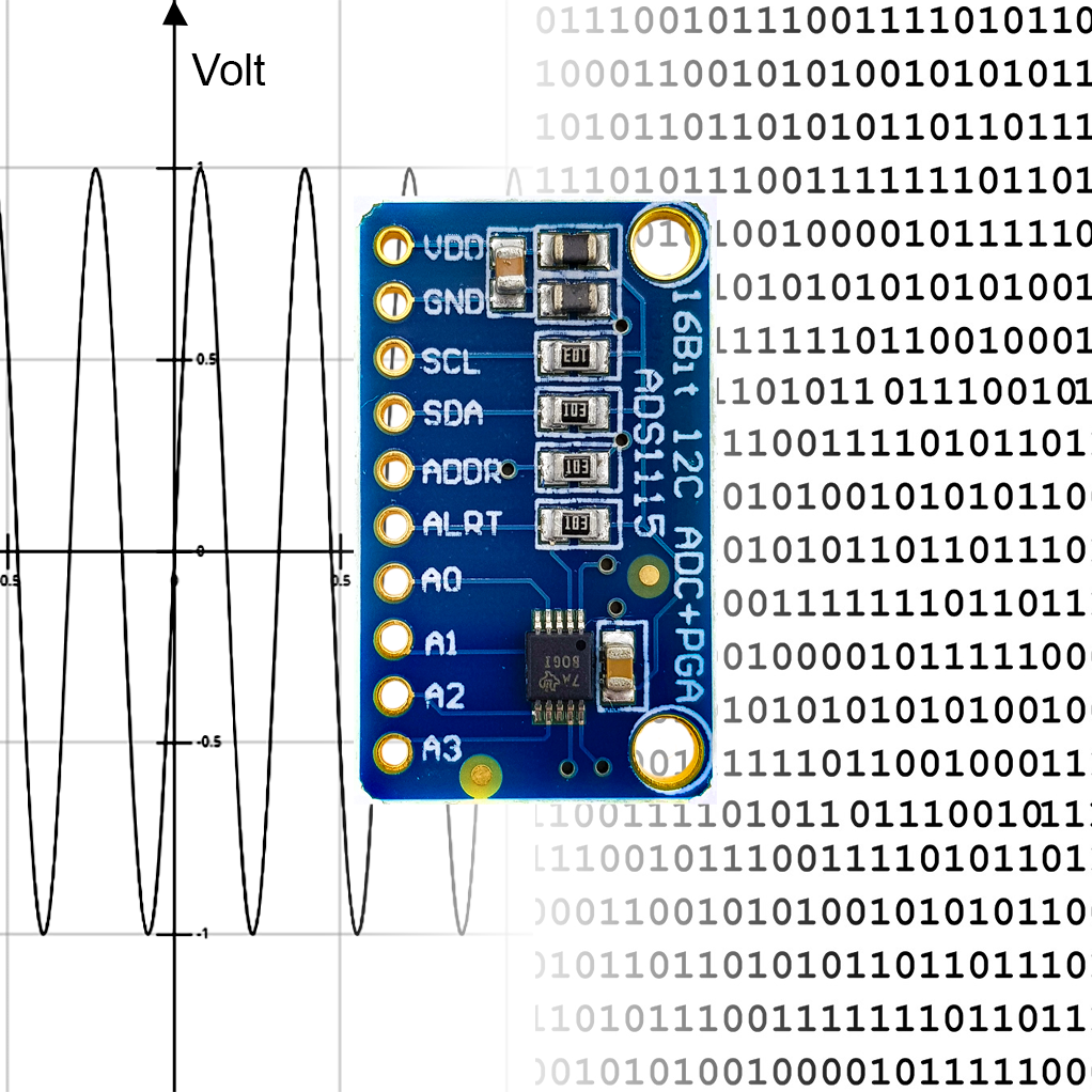
In this article, I would like to introduce the 16-bit, 4-channel A/D converter ADS1115 and its sibling, the 12-bit, 4-channel A/D converter ADS1015. You can control both with my ADS1115_WE library.
I will first go into the technical features, then I will use example sketches to show you how you can use the ADS1115 (and the ADS1015) with the library. Finally, there will be – for those who are interested – a deeper insight into the ADS1115 and its registers.
To be precise, this article deals with ADS1115 / ADS1015 modules. If you are skilled at soldering SMDs, you can of course also use the “bare” ADS1115 / ADS1015. My library should work the same way.
Why do I need the ADS1115 or the ADS1015?
“My Arduino or microcontroller already has a built-in A/D converter. So why should I deal with this external A/D converter?”
Here are a few reasons. The ADS1115
- has a resolution of 16 bits compared to the 10 bits of the Arduino.
- uses an internal amplifier so that it can measure even small voltages.
- has an alert function that you can use to efficiently monitor voltages, because:
- if your microcontroller has nothing else to do, you could send it to sleep and let the power efficient ADS1115 work.
- outsourced processes that are connected via interrupts can simplify your code.
The ADS1015 has a resolution of 12 bits but is considerably faster than the ADS1115.
Technical features of the ADS1115 / ADS1015
Inputs and outputs of the ADS1115 / ADS1015
The ADS1115 / ADS1015 and the modules have the following inputs and outputs:
- VCC / GND: To be connected to 2 to 5.5 volts.
- SDA / SCL: Communication via I2C. I didn’t need any extra pull-up resistors, but they’re not necessarily implemented in every module.
- ADDR: Address pin – you can choose from four I2C addresses according to the table shown below.
- ALRT: the alert pin asserts when adjustable thresholds are exceeded or when an A/D conversion (“conversion ready”) is completed. By default, the pin is deactivated.
- A0 – A3: Connections for the four channels. The applied voltage must not exceed VCC by more than 0.3 volts!
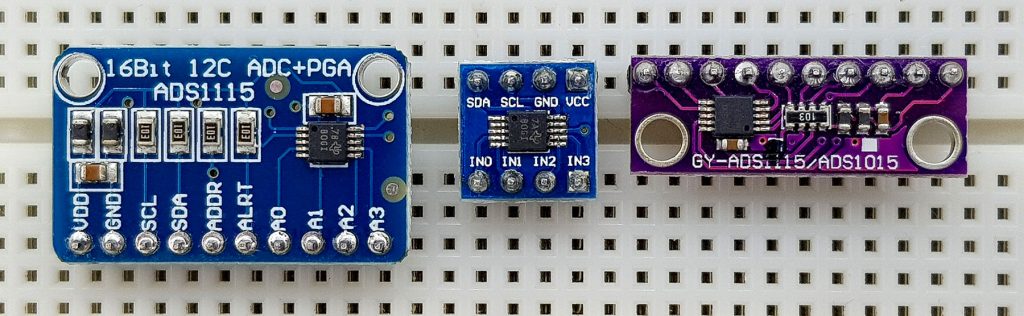
As you can see, the middle module shown above does not have an address and alarm pin. Thus, you can’t change the address 0x48 and use the alert functions. If you don’t need it, you have a very space-saving solution with such a module.
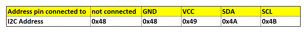
If you want to check the I2C address, you can use this I2C scanner.
attributes
Here is a brief overview of the most important features:
- 16 bit Resolution – signed (+/- 215 Bit).
- 12 bit for the ADS1015
- 4 channels that can be measured against each other or against GND.
- Multiplexing, so only one channel can be converted per time.
- 6 voltage (or gain) ranges from +/- 256 mV to +/- 6.144 V.
- Alert function (limit overrun or “conversion ready”).
- Conversion rate from 8 s-1 to 860 s-1.
- For the ADS1015: 128 s-1 to 3300 s-1
- Continuous mode or single-shot.
- Internal voltage reference.
- Low power consumption: 150 µA in continuous mode, 2.5 µA in power-down mode. The ADS1115 / ADS1015 automatically enters power-down mode after a single-shot measurement.
Further information can be found in the data sheet of the ADS1115.
ADS1115/ADS1015 modules are available for a few euros in most online stores, e.g. here on Amazon.
Apparently, there are also ADS1115 modules that do not deliver 16-bit resolution because they are incorrectly based on an ADS1015. There are also ADS1015 modules that are incorrectly based on ADS1115 modules. You can use my sample sketch “Who_AM_I.ino” to check which chip is installed.
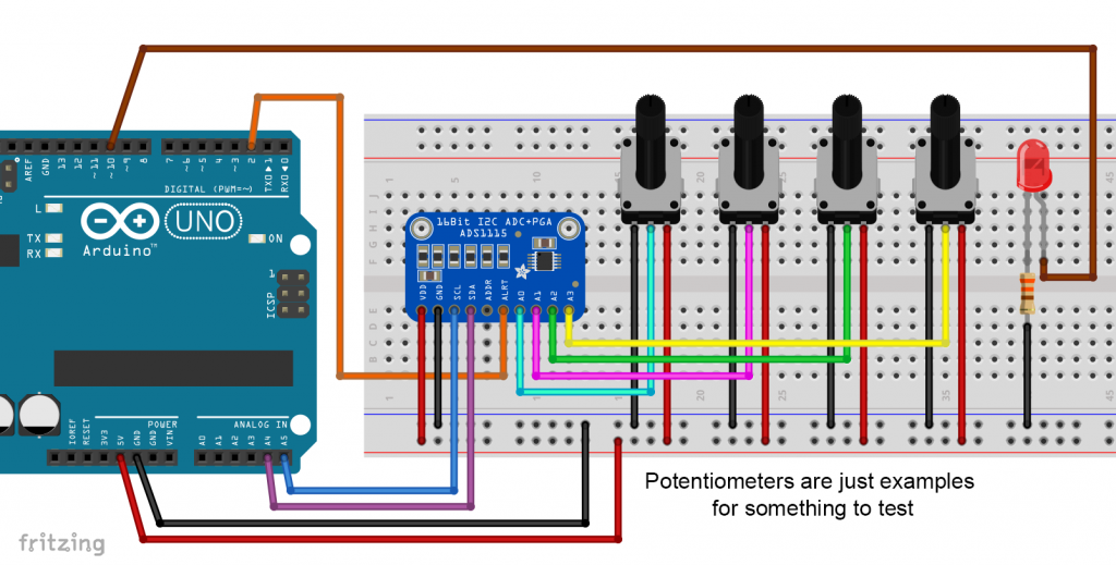
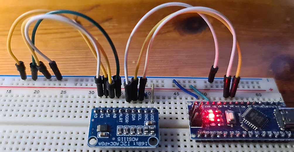
Typical circuit
I used the circuit shown below for all example sketches. Instead of the potentiometers you can, of course, connect anything else to the inputs. You could use a multimeter to check the results, or you could measure in parallel with the analog inputs of the Arduino.
As already mentioned, I didn’t need pull-ups for the I2C lines. If you have problems, add them.
Control with the ADS1115_WE library
You can download the library with the Arduino Library Manager or directly here from GitHub.
The use of example sketches is the most effective way to explain how to use the ADS1115_WE library. I have added various example sketches to the library. I go most intensively into Single_Shot.ino. Many functions used there are also used in other sketches. The sketches are written for the ADS1115. The “translation” for the ADS1015 is simple. You will find the example sketch “Continuous_ADS1015.ino” as part of the library.
Example sketch 1: Single_Shot.ino
With this sketch, we measure the four inputs in single-shot mode (i.e. on request) against GND one after the other. The parameters for the library functions you can choose from are listed in the comments in the sketch. A few notes on the (relevant) functions:
ADS1115_WE adc = ADS1115_WE()creates the ADS1115_WE object. You can pass alternative I2C addresses and buses.init()resets the settings of the configuration register of the ADS1115 to the default values. This has the advantage that you do not have to disconnect the ADS1115 from the power supply after you have changed your sketch. Otherwise, you would have to do this to have a defined state of the registers.init()also checks the connection to the module. The function returns false if the ADS1115 does not respond.setVoltageRange_mV()determines the voltage range in millivolts. The smaller the range, the greater the gain and resolution (= +/-range / 215).setCompareChannels()sets the channels to be compared.setConversionRate()sets the conversion rate in conversions per second (SPS = Samples per second).setMeasureMode()sets the mode, i.e. continuous or single-shot. The latter is the default.startSingleMeasurement()starts a conversion for the channels previously selected withsetCompareChannels().isBusy()returns true while the conversion is not yet complete. Without the linewhile(adc.isBusy()){}, the value from the last conversion would be read—and that may come from a different channel. There is only one conversion register!getResult_V()delivers the voltage in volts. For small values you can usegetResult_mV().
The other functions only become relevant when you use the alert pin.
/***************************************************************************
* Example sketch for the ADS1115_WE library
*
* This sketch shows how to use the ADS1115 in single shot mode.
*
* Further information can be found on:
* https://wolles-elektronikkiste.de/ads1115 (German)
* https://wolles-elektronikkiste.de/en/ads1115-a-d-converter-with-amplifier (English)
*
***************************************************************************/

#include<ADS1115_WE.h>
#include<Wire.h>
#define I2C_ADDRESS 0x48

/* There are several ways to create your ADS1115_WE object:
 * ADS1115_WE adc = ADS1115_WE()             -> uses Wire / I2C Address = 0x48
 * ADS1115_WE adc = ADS1115_WE(I2C_ADDRESS)  -> uses Wire / I2C_ADDRESS
 * ADS1115_WE adc = ADS1115_WE(&wire2)       -> uses the TwoWire object wire2 / I2C_ADDRESS
 * ADS1115_WE adc = ADS1115_WE(&wire2, I2C_ADDRESS) -> all together
 * Successfully tested with two I2C busses on an ESP32
 */
ADS1115_WE adc = ADS1115_WE(I2C_ADDRESS);

void setup() {
  Wire.begin();
  Serial.begin(9600);
  if(!adc.init()){
    Serial.println("ADS1115 not connected!");
  }

  /* Set the voltage range of the ADC to adjust the gain
   * Please note that you must not apply more than VDD + 0.3V to the input pins!
   *
   * ADS1115_RANGE_6144  ->  +/- 6144 mV
   * ADS1115_RANGE_4096  ->  +/- 4096 mV
   * ADS1115_RANGE_2048  ->  +/- 2048 mV (default)
   * ADS1115_RANGE_1024  ->  +/- 1024 mV
   * ADS1115_RANGE_0512  ->  +/- 512 mV
   * ADS1115_RANGE_0256  ->  +/- 256 mV
   */
  adc.setVoltageRange_mV(ADS1115_RANGE_6144); //comment line/change parameter to change range

  /* Set the inputs to be compared
   *
   *  ADS1115_COMP_0_1    ->  compares 0 with 1 (default)
   *  ADS1115_COMP_0_3    ->  compares 0 with 3
   *  ADS1115_COMP_1_3    ->  compares 1 with 3
   *  ADS1115_COMP_2_3    ->  compares 2 with 3
   *  ADS1115_COMP_0_GND  ->  compares 0 with GND
   *  ADS1115_COMP_1_GND  ->  compares 1 with GND
   *  ADS1115_COMP_2_GND  ->  compares 2 with GND
   *  ADS1115_COMP_3_GND  ->  compares 3 with GND
   */
  //adc.setCompareChannels(ADS1115_COMP_0_GND); //uncomment if you want to change the default

  /* Set number of conversions after which the alert pin will assert
   * - or you can disable the alert
   *
   *  ADS1115_ASSERT_AFTER_1  -> after 1 conversion
   *  ADS1115_ASSERT_AFTER_2  -> after 2 conversions
   *  ADS1115_ASSERT_AFTER_4  -> after 4 conversions
   *  ADS1115_DISABLE_ALERT   -> disable comparator / alert pin (default)
   */
  //adc.setAlertPinMode(ADS1115_ASSERT_AFTER_1); //uncomment if you want to change the default

  /* Set the conversion rate in SPS (samples per second)
   * Options should be self-explaining:
   *
   *  ADS1115_8_SPS
   *  ADS1115_16_SPS
   *  ADS1115_32_SPS
   *  ADS1115_64_SPS
   *  ADS1115_128_SPS (default)
   *  ADS1115_250_SPS
   *  ADS1115_475_SPS
   *  ADS1115_860_SPS
   */
  //adc.setConvRate(ADS1115_128_SPS); //uncomment if you want to change the default

  /* Set continuous or single shot mode:
   *
   *  ADS1115_CONTINUOUS  ->  continuous mode
   *  ADS1115_SINGLE     ->  single shot mode (default)
   */
  //adc.setMeasureMode(ADS1115_CONTINUOUS); //uncomment if you want to change the default

   /* Choose maximum limit or maximum and minimum alert limit (window) in volts - alert pin will
   *  assert when measured values are beyond the maximum limit or outside the window
   *  Upper limit first: setAlertLimit_V(MODE, maximum, minimum)
   *  In max limit mode the minimum value is the limit where the alert pin assertion will be
   *  be cleared (if not latched)
   *
   *  ADS1115_MAX_LIMIT
   *  ADS1115_WINDOW
   *
   */
  //adc.setAlertModeAndLimit_V(ADS1115_MAX_LIMIT, 3.0, 1.5); //uncomment if you want to change the default

  /* Enable or disable latch. If latch is enabled the alert pin will assert until the
   * conversion register is read (getResult functions). If disabled the alert pin assertion
   * will be cleared with next value within limits.
   *
   *  ADS1115_LATCH_DISABLED (default)
   *  ADS1115_LATCH_ENABLED
   */
  //adc.setAlertLatch(ADS1115_LATCH_ENABLED); //uncomment if you want to change the default

  /* Sets the alert pin polarity if active:
   *
   * ADS1115_ACT_LOW  ->  active low (default)
   * ADS1115_ACT_HIGH ->  active high
   */
  //adc.setAlertPol(ADS1115_ACT_LOW); //uncomment if you want to change the default

  /* With this function the alert pin will assert, when a conversion is ready.
   * In order to deactivate, use the setAlertLimit_V function
   */
  //adc.setAlertPinToConversionReady(); //uncomment if you want to change the default

  Serial.println("ADS1115 Example Sketch - Single Shot Mode");
  Serial.println("Channel / Voltage [V]: ");
  Serial.println();
}

void loop() {
  float voltage = 0.0;

  Serial.print("0: ");
  voltage = readChannel(ADS1115_COMP_0_GND);
  Serial.print(voltage);

  Serial.print(",   1: ");
  voltage = readChannel(ADS1115_COMP_1_GND);
  Serial.print(voltage);

  Serial.print(",   2: ");
  voltage = readChannel(ADS1115_COMP_2_GND);
  Serial.print(voltage);

  Serial.print(",   3: ");
  voltage = readChannel(ADS1115_COMP_3_GND);
  Serial.println(voltage);

  delay(1000);
}

float readChannel(ADS1115_MUX channel) {
  float voltage = 0.0;
  adc.setCompareChannels(channel);
  adc.startSingleMeasurement();
  while(adc.isBusy()){}
  voltage = adc.getResult_V(); // alternative: getResult_mV for Millivolt
  return voltage;
}
Example sketch 2: Continuous.ino
In this example, the ADS1115 measures continuously. Here, too, we switch channels again. The ADS1115 can always be read, regardless of whether the conversion register has been updated since the last read. Once the channel has been changed, it takes approximately two conversions before a new measurement value is available. To prevent values from being read from the previous channel, a delay() matched to the data rate is inserted when changing channels. The library does this in the background.
The main difference in the code is that the measurement does not need to be initiated.
I show here only the relevant or changed lines. Download the full sketches with the library.
  adc.setVoltageRange_mV(ADS1115_RANGE_6144); // wir nutzen wieder die ganze Range
  ....
  ....

  adc.setCompareChannels(ADS1115_COMP_0_GND); // we start with this channel
  ....
  ....
  adc.setMeasureMode(ADS1115_CONTINUOUS); // here we select continuous mode

void loop() {
  float voltage = 0.0;

  Serial.print("0: ");
  voltage = readChannel(ADS1115_COMP_0_GND);
  Serial.print(voltage);

  Serial.print(",   1: ");
  voltage = readChannel(ADS1115_COMP_1_GND);
  Serial.print(voltage);
  ....
  ....
  delay(1000);
}

float readChannel(ADS1115_MUX channel) {
  float voltage = 0.0;
  adc.setCompareChannels(channel);
  voltage = adc.getResult_V(); // we just retrieve a new value no startSingleMeasurement() needed
  return voltage;
}
Otherwise, the sketch should be understandable without further explanation.
Example sketch 3: Single_Shot_Conv_Ready_Controlled.ino
I have chosen a somewhat unwieldy name for the sketch. What I mean to say is that the ADS1115 measures in single-shot mode and controls the frequency of value output via the number of completed measurements and the conversion rate. I have set the conversion rate to 8 SPS. At every 32nd conversion the sketch outputs a value, i.e. every 4 seconds. Of course, you don’t have to measure 32 times to read a value. I only did this to slow down the output. It should be clear that the output is controlled by the data rate rather than a delay.
  adc.setVoltageRange_mV(ADS1115_RANGE_6144);
  ....
  ....
  adc.setCompareChannels(ADS1115_COMP_0_GND);
  ....
  ....
  adc.setConvRate(ADS1115_8_SPS); // 8 conversions per second
  ....
  ....
  //adc.setMeasureMode(ADS1115_CONTINUOUS); // commented, hence default is applied (single-shot)
  ....
  ....
void loop() {
  float voltage = 0.0;
  for(int i=0; i<32; i++){ // wait for 32 conversions
    adc.startSingleMeasurement();
    while(adc.isBusy()){}
  }
  voltage = adc.getResult_V(); // alternative: getResult_mV for Millivolt
  Serial.print("Channel 0 vs GND [V]: ");
  Serial.println(voltage);
  Serial.println("-------------------------------");
}
Example sketch 4: Conv_Ready_Alert_Pin_Controlled.ino
Another unwieldy name. This sketch also controls the output frequency by the number of conversions made. Unlike the last example, the Arduino does not ask for completion with isBusy(), but the ADS1115 reports this event via the alert pin. If this goes LOW (asserts), an interrupt is triggered that increments the counter variable.
Again, I am only performing the 32 measurements to slow down the output.
As new functions, the sketch uses:
setAlertPinMode()normally determines after how many limit overruns the alert pin asserts (1, 2 or 4). Actually, this is not relevant here. However, if you do not call the function, the default setting will be applied (ADS1115_DISABLE_ALERT). This means: the function must be called for this sketch with any parameter except ADS1115_DISABLE_ALERT.setAlertPol()determines whether the alarm pin is LOW or HIGH in the event of an alert. The default setting is LOW (ADS1115_ACT_LOW).setAlertPinToConversionReady()tells the ADS1115 that the alert should be triggered when the conversion is completed.
The Conversion Ready alarm also works in continuous mode. However, this only applies to the alarm pin, i.e., the query via hardware. The software query via isBusy() only works in single-shot mode.
....
....
int interruptPin = 2;
volatile bool convReady = false;
....
....
void setup() {
  ....
  ....
  pinMode(interruptPin, INPUT_PULLUP);
  ....
  ....
  adc.setVoltageRange_mV(ADS1115_RANGE_6144);
  ....
  ....
  adc.setCompareChannels(ADS1115_COMP_0_GND);
  ....
  ....
  adc.setAlertPinMode(ADS1115_ASSERT_AFTER_1);
  ....
  ....
  adc.setConvRate(ADS1115_8_SPS); //comment line/change paramater to change SPS
  ....
  ....
  //adc.setMeasureMode(ADS1115_CONTINUOUS); // commented --> single-shot
  ....
  ....
  //adc.setAlertPol(ADS1115_ACT_LOW); // active-low
  ....
  ....
  adc.setAlertPinToConversionReady(); // sets the alert pin to conversion ready
  ....
  ....
  attachInterrupt(digitalPinToInterrupt(interruptPin), convReadyAlert, FALLING); // interrupt, if alert pin is low, ISR = convReadyAlert
  adc.startSingleMeasurement(); // start measurement
}

void loop() {
  float voltage = 0.0;
  static int counter = 0;
  if(convReady){
    counter++;
    convReady = false;
    if(counter==32){  // counter is 32, conversion rate is 8 SPS --> 4s
      voltage = adc.getResult_V();
      Serial.print("Channel 0 vs GND [V]: ");
      Serial.println(voltage);
      Serial.println("-------------------------------");
      counter = 0;
    }
    adc.startSingleMeasurement();
  }
}

void convReadyAlert(){  // Interrupt Service Routine (ISR)
   convReady = true;
}
Example sketch 5: Alert_Window_Mode.ino
Now we come to a very helpful feature of the ADS1115, namely the limit alarm. This allows you to monitor voltages very conveniently. However, there is only one register for the upper and lower limits, respectively, and not for each channel. If you want to set the limits for each channel individually, you will have to do so again after each channel change.
The alert pin asserts if you exceed the limits set by you. The conditions under which the ADS1115 deasserts the alert pin again depends on further settings.
The following new function is relevant:
setAlertModeAndLimit():- Sets the mode:
- With ADS1115_WINDOW, you define a window with maximum and minimum. If values outside the limits are detected, the alert pin asserts. If the ADS1115 then determines values within the limit, the alert pin is deasserted – unless latch is active.
- With ADS1115_MAX_LIMIT, the alert pin only asserts if the maximum is exceeded. The minimum is the value the assertion ends – unless latch is active.
- In addition to the mode, the function also passes the limits in volts.
- Sets the mode:
You can find out what latch is all about in example sketch 6. In the current example, the alert pin automatically deassert when the above conditions occur.
Note: with assert and deassert I mean “alert on” / alert off”. Deassert does not mean that the alert pin is without function.
....
....
int ledPin = 10; // LED that indicates an alert
volatile bool outOfLimit = false;
....
....

void setup() {
  ....
  pinMode(interruptPin, INPUT_PULLUP);
  pinMode(ledPin, OUTPUT);
  digitalWrite(ledPin, LOW);
  ....
  ....
  adc.setCompareChannels(ADS1115_COMP_0_GND);
  ....
  ....
  adc.setAlertPinMode(ADS1115_ASSERT_AFTER_1); // alert after 1 value that is out of limit
  ....
  ....
  adc.setMeasureMode(ADS1115_CONTINUOUS); // single-shot would make no sense here
  ....
  ....
  adc.setAlertModeAndLimit_V(ADS1115_WINDOW, 3.0, 1.5); //you can change modes / limits
  ....
  ....
  //adc.setAlertPinToConversionReady(); // must be commented
  ....
  attachInterrupt(digitalPinToInterrupt(interruptPin), outOfLimitAlert, FALLING);
}

void loop() {
  float voltage = 0.0;
  if(outOfLimit){
    voltage = adc.getResult_V();
    Serial.print("Voltage [V]: ");
    Serial.println(voltage);
    digitalWrite(ledPin,HIGH);
    delay(1000);
    digitalWrite(ledPin,LOW);
    outOfLimit = false;
    attachInterrupt(digitalPinToInterrupt(interruptPin), outOfLimitAlert, FALLING);
  }
}

void outOfLimitAlert(){
  detachInterrupt(2);
  outOfLimit = true;
}
Example sketch 6: Alert_Window_Mode_with_Latch.ino
This sketch basically does the same as Alert_Window_Mode.ino, except that latch is used. Latch prevents the alert pin from being automatically deactivated again.
The following new functions are relevant:
setAlertLatch()activates or deactivates latch.clearAlert()deactivates the alert pin. Latch is active when the next reading is outside the limits. As an alternative toclearAlert()you can usegetResult_V()orgetResult_mV().
....
volatile int interruptPin = 2;
int ledPin = 10;
volatile bool outOfLimit = false;
....
....
void setup() {
  ....
  ....
  adc.setCompareChannels(ADS1115_COMP_0_GND);
  ....
  ....
  adc.setAlertPinMode(ADS1115_ASSERT_AFTER_1); // ...AFTER_2 or ...4 would also work
  ....
  ....
  adc.setMeasureMode(ADS1115_CONTINUOUS);
  ....
  ....
  adc.setAlertModeAndLimit_V(ADS1115_WINDOW, 3.0, 1.5); // you could also select the max limit method
  ....
  ....
  adc.setAlertLatch(ADS1115_LATCH_ENABLED); // latch enabled
  ....
  ....
  attachInterrupt(digitalPinToInterrupt(interruptPin), outOfLimitAlert, FALLING);
}

void loop() {
  float voltage = 0.0;
  if(outOfLimit){
    voltage = adc.getResult_V();
    Serial.print("Voltage [V]: ");
    Serial.println(voltage);
    digitalWrite(ledPin,HIGH);
    delay(1000);
    digitalWrite(ledPin,LOW);
    outOfLimit = false;
    attachInterrupt(digitalPinToInterrupt(interruptPin), outOfLimitAlert, FALLING);
    adc.clearAlert(); // clear alert; alternatives: call getResult_V() or getResult_mV()
  }
}

void outOfLimitAlert(){
  detachInterrupt(2);
  outOfLimit = true;
}
After the output of the exceeded limit value and the warning light of the LED, first the interrupt is switched on again. Then the alarm is deactivated with clearAlert(), i.e. the pin goes HIGH. If the out-of-limit condition still exists, the next interrupt is triggered immediately. As a result, the LED lights up almost continuously.
The latch provides more control, but you have to be careful with the timing. If you switch on the interrupt function after you have deactivated the alert, then the alert pin may be low again and a “falling” will not occur anymore.
Example sketch 7: Auto_Range.ino
In this example sketch, I present the functions setAutoRange() and setPermanentAutoRangeMode(). As you can imagine, the range is set automatically with both. To do this, setAutoRange() does the following:
- If the ADS1115 is in single-shot mode, the function switches to continuous mode.
- The maximum range (+/- 6.144) is set first.
- A measured value is recorded.
- The smallest possible range is then selected in which the measured value is still below 80% of the maximum value of the range. I have selected 80% so that certain fluctuations do not immediately lead to an overflow.
- If the ADS1115 was originally in single-shot mode, it will switch back to this mode.
The function setAutoRange() only makes sense if the expected measured values are stable or change only slowly. A call to the function takes a period of several conversions. If you have set 8 SPS as the conversion rate, this is already clearly noticeable.
setPermanentAutoRangeMode() only needs to be called once. You can use it to set the system to check whether each measured value is within the range of 30 – 80 % of the maximum value of the current range. Only if this is not the case is setAutoRange() called up in the background. This makes the function faster. Uses one OR the other function.
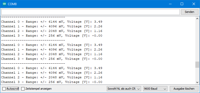
To show that the range change really works, the range is also output in the example sketch.
....
  adc.setMeasureMode(ADS1115_CONTINUOUS); //comment line/change parameter to change mode
  ....
  ....
  adc.setPermanentAutoRangeMode(true);  //use either this or setAutoRange()
  ....
}

void loop() {
  float voltage = 0.0;

  Serial.print("Channel 0 - ");
  readChannel(ADS1115_COMP_0_GND);

  Serial.print("Channel 1 - ");
  readChannel(ADS1115_COMP_1_GND);
  ....
  ....
  Serial.println("-------------------------------");
  delay(1000);
}

void readChannel(ADS1115_MUX channel) {
  float voltage = 0.0;
  adc.setCompareChannels(channel);
  //adc.setAutoRange(); //use either this or setPermanentAutoRangeMode(true)
  voltage = adc.getResult_V(); // alternative: getResult_mV for Millivolt
  printVoltageRange(); // this is just to show that the range is changing with changing voltages
  Serial.println(voltage);
}

void printVoltageRange(){
  unsigned int voltageRange = adc.getVoltageRange_mV();
  Serial.print("Range: ");

  switch(voltageRange){
    case 6144:
      Serial.print("+/- 6144 mV, Voltage [V]: ");
      break;
    case 4096:
      Serial.print("+/- 4096 mV, Voltage [V]: ");
      break;
    case 2048:
      Serial.print("+/- 2048 mV, Voltage [V]: ");
      break;
    case 1024:
      Serial.print("+/- 1024 mV, Voltage [V]: ");
      break;
    case 512:
      Serial.print("+/- 512 mV, Voltage [V]: ");
      break;
    case 256:
      Serial.print("+/- 256 mV, Voltage [V]: ");
      break;
    default:
      Serial.println("Something went wrong");
  }
}
Output of Auto_Range.ino
An output of the sketch could then look like this:
Example sketch 8: Result_Format_Options
This sketch shows the various output options for the conversion results:
getResult_mV()returns the result in millivoltsgetResult_V()outputs the result in voltsgetRawResult()returns the raw value as it appears in the conversion register- With
getResultWith Range(x,y)the raw value is scaled to the range x to y. If you select (-1023, 1023), for example, you will get your result back as a 10-bit value. - If you call the last function with a third parameter like
getResultWithRange(x,y,z), the result is also scaled to a voltage range. The parameter is specified in millivolts. The parameters (-1023, 1023, 5000) would give you the value that you would get with analogRead() with an Arduino Uno R3 in the default settings.
 ....
  adc.setVoltageRange_mV(ADS1115_RANGE_6144); //comment line/change parameter to change range
  adc.setCompareChannels(ADS1115_COMP_0_GND); //comment line/change parameter to change channel
  adc.setMeasureMode(ADS1115_CONTINUOUS); //comment line/change parameter to change mode
  ....
  ....

void loop() {

  float voltageInMillivolt = adc.getResult_mV();
  Serial.print("Result in Millivolt          [mV]: ");
  Serial.println(voltageInMillivolt);

  float voltageInVolt = adc.getResult_V();
  Serial.print("Result in Volt                [V]: ");
  Serial.println(voltageInVolt);

  int rawResult = adc.getRawResult();
  Serial.print("Raw Result                       : ");
  Serial.println(rawResult);

  int scaledResult = adc.getResultWithRange(-1023, 1023);
  Serial.print("Scaled result                    : ");
  Serial.println(scaledResult);

  int scaledResultWithMaxVoltage = adc.getResultWithRange(-1023, 1023, 5000);
  Serial.print("Scaled result with voltage scale : ");
  Serial.println(scaledResultWithMaxVoltage);

  unsigned int voltRange = adc.getVoltageRange_mV();
  Serial.print("Voltage Range of ADS1115     [mV]: ");
  Serial.println(voltRange);

  Serial.println("-------------------------------");
  delay(2000);
}
Output of Result_Format_Options.ino
And this is what an output of the Result_Format_Option.ino sketch looks like:

All functions at a glance
Here I have summarized all the functions. The table is part of my documentation on GitHub. However, you can also find the table as “List of public functions.pdf” in the library folder “libraries/ADS1115_WE” on your PC, provided you have installed the library.
I have not mentioned one function yet, namely reset() . It uses the global I2C reset (0x06). All I2C devices that are connected to the same interface and also listen to the global commands (general calls) perform a reset when the function is called.
Deeper insights into the ADS1115 / ADS1015
I am referring to the ADS1115 in this chapter. The good news is that the registers of the ADS1015 are almost identical. For all registers where its 12-bit resolution is used, the lowest 4 bits are simply set to 0.
Register map
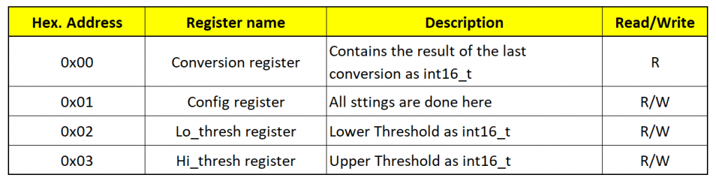
The ADS1115 has a relatively small number of registers. All settings – with one exception – are made in the configuration register (config register). I’ll go into that in a little bit.
The results of the conversions are retrieved from the conversion register. There is only one for all four channels. Therefore, you always have to select the channel first and then wait for a result for this channel. The LSB for the conversion register is:
![\[ LSB = \frac{Range}{2^{15}} \]](https://wolles-elektronikkiste.de/wp-content/ql-cache/quicklatex.com-9f34c41a5e8089a676a9afda40f46853_l3.png "Rendered by QuickLaTeX.com")
If you have defined the range, as I did, in millivolts, you then calculate the voltage in volts as follows:
![\[ U \text{[V]} = \frac{LSB \cdot ConvRegister}{1000} \]](https://wolles-elektronikkiste.de/wp-content/ql-cache/quicklatex.com-b74bdea25a7bca81db277364de84ef90_l3.png "Rendered by QuickLaTeX.com")
Because the conversion register is signed, it can take values from +215 to -215.
Reading the conversion register deletes a limit alert unless latch is enabled.
In the two limit registers (Lo_thresh and Hi_thesh) you enter the limit values if you want to use the alert function. The ADS1115 compares the content of the limit registers with the content of the conversion register. If you change the range, you must also convert the content of the limit registers. My library does this automatically. As a result, my function setVoltageRange() has become somewhat complex.
The only setting you make outside the configuration register (excluding the limits, of course) is to set the conversion ready alert. To activate this function, you need to write a “1” in the MSB of the Hi_thresh register and a “0” in the MSB of the Lo_thresh register. Since the limit registers are signed, the upper limit is negative and the lower one is positive. This condition, meaningless in itself, instructs the ADS1115 to activate the alert pin when a conversion is complete. The library provides the function setAlertPinToConversionReady() for this purpose.
The configuration register
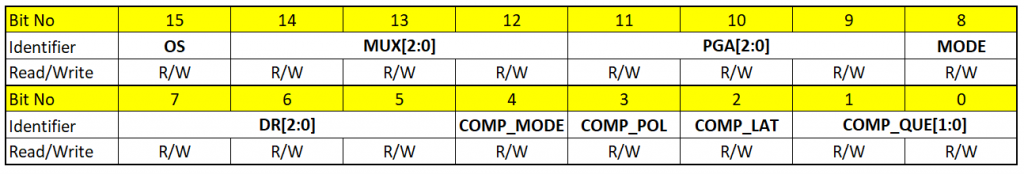
The configuration register contains the following bits:
- COMP_QUE[1:0]: defines after how many “out-of-range” measurements the ADS1115 activates the alarm pin. Alternatively, the bits switch off the alarm function. The associated function is
setAlertPinMode(). - COMP_LAT activates or deactivates latch. If latch is activated, you must manually deactivate the alert. The COMP_LAT bit is set or deleted with
setAlertLatch(). - COMP_POL determines the polarity of the alert pin ->
setAlertPol(). - COMP_MODE determines the alarm mode. Either you define an upper limit or a window. The associated function
setAlertModeAndLimit()determines the mode and sets the limits. - DR[2:0] determines the conversion rate ->
setConvRate(). - MODE: sets the continuous or single-shot mode ->
setMeasureMode(). - PGA[2:0] sets the range ->
setVoltageRange_mV(); - MUX[2:0] determines the channel or channels to be compared ->
setCompareChannels(). - OS has a double meaning. When writing, a “1” in single-shot mode triggers a measurement – >
startSingleMeasurement(). When reading, a “0” means that a conversion is ongoing, and a “1” means the opposite. The function for this isisBusy().
Good afternoon.
I am experimenting with ADS1115 type ADCs using your ADS1115_WE library.
I connected all the ADS1115 inputs (AIN0 – AIN3) to each other and connected them to GND.
Sketch – Single Shot Mode
Results:
ADS1115 Example Sketch – Single Shot Mode
Channel / Voltage [V]:
0: -0.00, 1: -0.00, 2: 0.54, 3: 0.49
0: -0.00, 1: -0.00, 2: 0.50, 3: 0.54
0: -0.00, 1: -0.00, 2: 0.54, 3: 0.49
0: -0.00, 1: -0.00, 2: 0.50, 3: 0.54
0: -0.00, 1: -0.00, 2: 0.53, 3: 0.49
0: -0.00, 1: -0.00, 2: 0.51, 3: 0.54
0: -0.00, 1: -0.00, 2: 0.51, 3: 0.51
0: -0.00, 1: -0.00, 2: 0.52, 3: 0.53
0: -0.00, 1: -0.00, 2: 0.50, 3: 0.52
0: 0.00, 1: -0.00, 2: 0.53, 3: 0.51
0: -0.00, 1: -0.00, 2: 0.49, 3: 0.54
0: -0.00, 1: 0.00, 2: 0.54, 3: 0.49
0: 0.00, 1: -0.00, 2: 0.50, 3: 0.54
0: -0.00, 1: -0.00, 2: 0.54, 3: 0.49
0: -0.00, 1: 0.00, 2: 0.50, 3: 0.54
0: 0.00, 1: -0.00, 2: 0.52, 3: 0.50
0: -0.00, 1: -0.00, 2: 0.51, 3: 0.53
0: -0.00, 1: -0.00, 2: 0.51, 3: 0.51
Where does the 0.5 V voltage come from at the AIN2 and AIN3 inputs?
Added differential measurements:
….
Serial.print(“, 3: “);
voltage = readChannel(ADS1115_COMP_3_GND);
Serial.print(voltage);
Serial.print(“, 0_1: “);
voltage = readChannel(ADS1115_COMP_0_1);
Serial.print(voltage);
Serial.print(“, 0_3: “);
voltage = readChannel(ADS1115_COMP_0_3);
Serial.print(voltage);
Serial.print(“, 1_3: “);
voltage = readChannel(ADS1115_COMP_1_3);
Serial.print(voltage);
Serial.print(“, 2_3: “);
voltage = readChannel(ADS1115_COMP_2_3);
Serial.println(voltage);
delay(1000);
….
Result:
ADS1115 Example Sketch – Single Shot Mode
Channel / Voltage [V]:
0: -0.00, 1: 0.00, 2: 0.51, 3: 0.54, 0_1: 0.00, 0_3: -0.51, 1_3: -0.52, 2_3: 0.00
0: -0.00, 1: -0.00, 2: 0.50, 3: 0.55, 0_1: 0.00, 0_3: -0.49, 1_3: -0.52, 2_3: 0.00
0: -0.00, 1: -0.00, 2: 0.50, 3: 0.54, 0_1: 0.00, 0_3: -0.50, 1_3: -0.50, 2_3: 0.00
0: -0.00, 1: -0.00, 2: 0.52, 3: 0.53, 0_1: 0.00, 0_3: -0.52, 1_3: -0.49, 2_3: 0.00
0: -0.00, 1: -0.00, 2: 0.53, 3: 0.52, 0_1: 0.00, 0_3: -0.52, 1_3: -0.47, 2_3: 0.00
0: -0.00, 1: -0.00, 2: 0.54, 3: 0.50, 0_1: 0.00, 0_3: -0.51, 1_3: -0.46, 2_3: 0.00
0: -0.00, 1: -0.00, 2: 0.53, 3: 0.49, 0_1: 0.00, 0_3: -0.50, 1_3: -0.48, 2_3: 0.00
0: -0.00, 1: -0.00, 2: 0.53, 3: 0.50, 0_1: 0.00, 0_3: -0.48, 1_3: -0.49, 2_3: 0.00
0: -0.00, 1: -0.00, 2: 0.51, 3: 0.51, 0_1: 0.00, 0_3: -0.46, 1_3: -0.51, 2_3: 0.00
0: -0.00, 1: -0.00, 2: 0.49, 3: 0.53, 0_1: 0.00, 0_3: -0.47, 1_3: -0.52, 2_3: 0.00
0: -0.00, 1: -0.00, 2: 0.49, 3: 0.54, 0_1: 0.00, 0_3: -0.48, 1_3: -0.52, 2_3: 0.00
0: -0.00, 1: -0.00, 2: 0.51, 3: 0.54, 0_1: 0.00, 0_3: -0.50, 1_3: -0.50, 2_3: 0.00
0: -0.00, 1: -0.00, 2: 0.52, 3: 0.53, 0_1: 0.00, 0_3: -0.52, 1_3: -0.48, 2_3: 0.00
0: 0.00, 1: -0.00, 2: 0.53, 3: 0.51, 0_1: 0.00, 0_3: -0.52, 1_3: -0.47, 2_3: 0.00
0: 0.00, 1: -0.00, 2: 0.54, 3: 0.49, 0_1: 0.00, 0_3: -0.51, 1_3: -0.47, 2_3: 0.00
0: -0.00, 1: -0.00, 2: 0.53, 3: 0.49, 0_1: 0.00, 0_3: -0.49, 1_3: -0.49, 2_3: 0.00
0: -0.00, 1: -0.00, 2: 0.51, 3: 0.51, 0_1: 0.00, 0_3: -0.47, 1_3: -0.51, 2_3: 0.00
0: -0.00, 1: -0.00, 2: 0.49, 3: 0.53, 0_1: 0.00, 0_3: -0.47, 1_3: -0.52, 2_3: 0.00
0: -0.00, 1: -0.00, 2: 0.49, 3: 0.54, 0_1: 0.00, 0_3: -0.48, 1_3: -0.52, 2_3: 0.00
0: -0.00, 1: -0.00, 2: 0.51, 3: 0.54, 0_1: 0.00, 0_3: -0.51, 1_3: -0.50, 2_3: 0.00
0: -0.00, 1: 0.00, 2: 0.52, 3: 0.53, 0_1: 0.00, 0_3: -0.52, 1_3: -0.48, 2_3: 0.00
0: -0.00, 1: -0.00, 2: 0.54, 3: 0.50, 0_1: 0.00, 0_3: -0.52, 1_3: -0.46, 2_3: 0.00
Hi, I have just tried to reproduce what you have done (your first comment). I have connected all ADS1115 inputs to GND:
I took the Single Shot example as is without any change and get -0.00 V for all four channels. Only if I disconnect one of the inputs from ground I get a value of 0.5 V for that channel.
I don’t know what’s different on your side. Do you want to send me a photo of your experiment? To: Wolfgang.Ewald@wolles-elektronikkiste.de.
Do you maybe use a breadboard with a splitted GND and VCC line?
I sent it away.
Thanks for sending the fotos. Bizarre! In essence it’s exactly the same I am doing. And I have even tried it on an Arduino UNO R4 WIFI now exactly your way, i.e. first connecting all the input pins AIN0-AIN3 and then connecting AIN0 to GND. Still I get 0.00 V (or -0.00 V to be exact) for all channels when using the Single Shot example. I will think about this, but currently I have no idea what could lead to this issue.
Thank you for your amazing library!
I am doing a project where I am using a force transducer as my sensor, connected to an amplifier. The amplifier’s analog ouput wire is then connected to channel 0 of the ADS1115, which is then connected to an esp32. My initial idea was to use esp32 to power all the circuit, however the amplifier needs a power supply of 12V, and it has a supply bridge of 5V for the transducer. So I am powering that part of the circuit with 12V.
The problem is the analog output voltage that I want to measure is maximum 3.3V against the amplifier’s ground, not the esp32 ground. And I took some time realising that… So now I was thinking, instead of comparing channel 0 to ground (which is esp32 ground), I could compare channel 0 to channel 1, and in channel 1 I would have the amplifiers ground.
I thought that could work but it turns out it doesn’t… So maybe I did not understand the setCompareChannels function correctly, since I assume it wasn’t about the comparator discribed in the datasheet but something different where you set the two points to measure differential voltage… Am I thinking completly wrong? Do you have any suggestions?
Thank you in advance!
Hi Francisca, the problem is that the voltage limits at the inputs A0 to A3 are GND – 0.3 volts to VDD + volts. So, even if the differential value is within these limits the absolute values must not exceed these limits. If you do so, you might damage the ADS1115. I guess that is not what you like to hear – sorry!
Wouldn’t such an i2c isolator solve your problem? I use it with ads1115 which is powered by 5V current with ground on the PV panels circuit, and esp32 3.3V. It works without problems and galvanically isolates esp32 from ads1115.
https://allegro.pl/oferta/stemma-qt-iso1540-bidirectional-i2c-isolator-modul-z-izolatorem-16318096319
Thank you! That could work. I was not aware of this part, which can be very helpful.
Hello Wolfgang Ewald
i count the number of measures with a adc.setConvRate(ADS1115_860_SPS); on serial monitor and it seems to be 166 SPS instead of 860 SPS
is there any way to increase the serial readings ?
this is my code:
float filtrado = 0;
#define alpha 0.06
unsigned long previousMillis1 = 0;
unsigned long interval1 = 1 ;
unsigned long currentMillis = 0;
float voltage = 0.0;
//—————————————-
#include
#include
#define I2C_ADDRESS 0x48
ADS1115_WE adc = ADS1115_WE(I2C_ADDRESS);
void setup() {
Wire.begin();
Serial.begin(115200);
if(!adc.init()){
Serial.println(“ADS1115 not connected!”);
}
adc.setVoltageRange_mV(ADS1115_RANGE_4096); //comment line/change parameter to change range
adc.setCompareChannels(ADS1115_COMP_0_GND); //comment line/change parameter to change channel
adc.setConvRate(ADS1115_860_SPS); //uncomment if you want to change the default
adc.setMeasureMode(ADS1115_CONTINUOUS); //comment line/change parameter to change mode
}
void loop() {
currentMillis = millis();
if ((currentMillis – previousMillis1) >= interval1) {
previousMillis1 = currentMillis;
voltage = readChannel(ADS1115_COMP_0_GND);
filtrado = (alpha * voltage) + ((1 – alpha) * filtrado);
Serial.println(filtrado,3);
}
}
float readChannel(ADS1115_MUX channel) {
float voltage = 0.0;
adc.setCompareChannels(channel);
voltage = adc.getResult_V(); // alternative: getResult_mV for Millivolt
return voltage;
}
Hi, Serial.print() is slow, but it’s also setCompareChannels() which slows down the output rate. The reason is a delay which I implemented when changing channels in the continuous mode. It’s two times the period of one measurement. The reason is that the ADS1115 is a multiplexer module. It has several channels but only one ADC. If you change the channel, the ADS1115 will first complete the ongoing measurement which is in worst case a complete measurement. Then it will start. Then it will start the next measurement.
The good news is that there are two options for you:
1) It seems you are not changing channels. Therefore change
* voltage = readChannel(ADS1115_COMP_0_GND) to voltage = readChannel()
* float readChannel(ADS1115_MUX channel) {
to float readChannel() {
* ans delete or comment adc.setCompareChannels(channel)
2) Alternatively change to the single Shop/ triggered Mode. For this I have not applied delays because everything is controlled by yorself.
Hope this helps!
Hi, I’m trying your library with Esp32 and ADS1115.
But I noticed that when I change the sampling rate (adc.setConvRate) the millivolt result also changes (adc.getResult_mV()).
I’m using the adc.startSingleMeasurement(); mode
This is not a good thing, that is, the millivolt calculation should be based on the various parameters that we have set
Thanks
Hi, how are the values changing? I will also check 1) if I can reproduce the issue and 2) if I can influence this by code. But not before next weekend.
The calculation of the millivolts from the raw values is independent from the sampling rate. The raw values are calculated by the ADS1115.
I have tried the following sketch:
#include<ADS1115_WE.h>
#include<Wire.h>
#define I2C_ADDRESS 0x48

ADS1115_WE adc = ADS1115_WE(I2C_ADDRESS);

void setup() {
  Wire.begin();
  Serial.begin(9600);
  adc.init();
  Serial.println("ADS1115 not connected!");
  adc.setVoltageRange_mV(ADS1115_RANGE_6144); //comment line/change parameter to change range
  adc.setCompareChannels(ADS1115_COMP_0_1); //uncomment if you want to change the default
}

void loop() {
  float voltage = 0.0;
  adc.setConvRate(ADS1115_8_SPS);
  for(int i=0; i<5; i++){
    delay(1000);
    adc.startSingleMeasurement();
    while(adc.isBusy()){}
    voltage = adc.getResult_mV();
    Serial.println(voltage,1);
  }
  adc.setConvRate(ADS1115_860_SPS);
  for(int i=0; i<5; i++){
    delay(1000);
    adc.startSingleMeasurement();
    while(adc.isBusy()){}
    voltage = adc.getResult_mV();
    Serial.println(voltage,1);
  }
  Serial.println("***************\n");
}
I tried a fixed voltage and typically got a result like this for the ten measurements:
2331.4
2331.4
2331.4
2331.4
2331.4
2333.4
2332.7
2330.1
2331.9
2331.6
Very stable for 8 SPS, more noise for 860 SPS, but quite similar. So, I can't confirm that the sampling range changes the results significantly. Maybe you can provide more details.
Hi Wolfgang,
Many thanks for a reliable library, with excellent documentation!
I’m using 2 x ADS1115 to get 8 inputs, and using the alert pins for ‘conversion ready’. I got tripped up though by the functionality of ‘conversion ready’.
As the alert pin is an open-drain output I connected them both together to a single MCU input, assuming that when the result is read, or when clearAlert() is called, the output would go inactive until a subsequent conversion completed.
This turns out to NOT be the case. The ONLY time the pin is false is when a conversion is actually in progress. This of course caused a problem with both alert pins connected together, as only one chip would have a conversion in progress so the other chip would be holding the signal true (low).
My solution was to disable the alert pin on the inactive chip before starting the conversion on the active one. A few extra instructions and it works fine.
I thought it might be worth mentioning this in your documentation so that other don’t fall into the same trap!
Regards,
Adrian.
I just realized that I could of course use setAlertPol() to set the active state (conversion complete) to high. Then only the chip currently converting would pull it low, so going high again would signal the end of the conversion.
Hi, great that you found a way to solve the problem. Might help others! Thanks.
Thank you for the wonderful library!!
I’m using the ads 1115 to record two differential channels connected to A/C current loops. I’m under the impression one can see negative channels values so long as they don’t exceed the -300mv limit. Do they actually clamp at 0V?
Also, have you seen any performance problems running the sample rate at 860hz for extended periods of time, as in days?
Hi, I can confirm that you can measure values exceeding VDD by 300 mV and I assume you can also go down to -300 mV vs. GND. However, I have not tried the latter. I should make this clear in the article. Beyond these limits, the ADS1115 might be destroyed.
I also have not tried yet to run the ADS1115 for several days at 860 Hz, but I have not heard that others experienced problems. May I ask what kind of performance problems you faced? Is it insufficient sample rate, noise, drift or something else?
Hi. Newbie here and i work on my first project , can I use timer interrupt library like timerone with your library. I tried and it complies but the device stop working as soon as timer is initialized. Thank you so much for any help
Hi Stan, I need some more information to help you. The easiest would be if you send me your code (wolfgang.ewald@wolles-elektronikkiste.de).
Regards, Wolfgang
Thank you Wolfgang for generously sharing your work. I am just now finding my way into ADS1115. Your code & library helped me a lot.
The most important insight that took me quite a while to grasp was:
the maximum allowable voltage (VDD+0.3V) doesn’t really matter, and neither does it make a difference whether I drive the chip with 3.3V or 5V – it almost always makes sense to set up a voltage divider and transpose the measured voltage down into a range that the ADS1115 can fully process. Without a voltage divider, even when measuring i.e. 3V or 5V directly, part of the required voltage range would be off limits due to overvoltage, effectively wasting ADS1115 precision. So using a voltage divider (or simply a potentiometer) can adjust the ADS1115 to almost any input voltage.
What I can’t seem to figure out though: even when I use a voltage divider and transpose the voltage into a safe range such as +-2.048V, I still only use half of the ADS1115 precision (since negative voltages cannot be directly measured).
So to fully leverage the ADS1115 capabilities, I would need to use a differential measurement and take my input voltage (i.e. 0-12V), and transpose it into the range -2 to +2V, feeding it into two of the ADS1115 inputs.
This is where I am really still struggling and lost. Do you by chance have a sketch for this (fully utilizing the ADS1115 precision)?
Many thanks!
Hi Tobias,
I think I know what you mean, but that won’t work. The allowed voltages you can attach to A0 – A3 are GND – 0.3V to VCC + 0.3V. You can only measure negative differences. So, let’s assume you attach a certain voltage to A0 and A1 and let’s assume the differential voltage is positive. Then you can swap A0 and A1 and you will get the same result but a negative output. But the voltage you apply to A0 has to be positive vs. GND, and it’s the same for A1.
If you are looking for an ADC that can deal with negative voltages (vs. GND) you could have a look at the ADS1220: https://wolles-elektronikkiste.de/en/4-channel-24-bit-adc-ads1220
And you should be aware that voltage dividers will lead to a certain error. The input impedance is high, but not infinite. It depends on the mode (differential vs. single-ended) and on the range. E.g., if you apply the +/- 2.048 range, single-ended, the impedance is 6 MOhm. You find these values in the datasheet (7.5 – electrical characteristics). Let’s assume you apply a voltage divider and its resistor on the GND side is 10 kOhm. Then you have 6 MOhm and 10 kOhm in parallel. If I calculate correctly (1/Rtotal = 1/R1 + 1/R2) the effective resistance is ~9.98 kOhm which is a deviation of 2%. That is quite significant – in particular for someone who is looking to get the last bit of resolution out of the ADS1115.
Hi Wolfgang,
Thank you for this excellent work, very well illustrated (I had lots of problems with other libraries). I began very recently with Arduino to make my own data logger to get rid of high costs and delivery delays of commercial products. I thank you for the very productive documents you provide.
While everything was ok in continuous mode I had problems with the single mode. I programmed bursts every minute to save energy, but is did not work… I prepared a long post to ask about needs to re-initalize between bursts… but I finally realized that a delay of 60000 mS (60 seconds) was not a good idea when integers cannot be higher than 32767 !! 60 successive delay(1000) work perfectly.
I am happy to contact you anyway just to thank you for the so much pedagogical information and examples you provide which was very useful to the poor beginner I am.
Regards,
JMM
Bonjours Jean-Marie,
thanks for your kind comment. I have to admit, I still make similar mistakes!
Regards, Wolfgang
Good day.
Is it possible for you to measure the value from the differential input? That is, I have both positive and negative voltage values in the range of +- 0.2V. It is also interesting what the maximum signal processing frequency will be. I have one idea for measuring the current, but the frequency there should be more than 100 times per second.
Thank you.
Hi, you can measure differential values. E.g. with setCompareChannels(ADS1115_COMP_0_1) you measure the difference between A0 and A1. The difference can be positive or negative, but the voltages applied to the input pins need to be positive.
Thank you
Wolfgang – again I switched from an AdaFruit library to one of your libraries. They should just pay you to write their libraries!
/Thanks for a great library,
m
Thank you for your kind comment! Much appreciated!
Hi!
Coole Bibliothek! Lief vom Fleck weg, musste Wettersensoren die eine Stromquelle darstellen auslesen.
Aber von der Zeile
while(adc.isBusy()){}
würde ich abraten, da ein ESP8266 wenn es dumm läuft crasht….
Stattdessen
while(adc.isBusy())
delay(1);
Statt der Microsekunde geht tatsächlich auch die 0 oder statt delay(…) yield()… Dann kann der ESP8266 in der Zeit seine “Hausaufgaben” (TCP/-IP-Stack abarbeiten, Register setzen und was sonst noch so zwischen den loop()-Aufrufen passiert) erledigen kann.
Hi, vielen Dank für den Hinweis. Allerdings würde ich dann eher die delay(0) nehmen oder yield() oder delayMicroseconds(1), da man sonst bei der schnellsten Datenrate (860 SPS) nur ca. die Hälfte der erwarteten Datenrate erzielt.
Auch bei den Interruptsketchen sind Anpassungen für ESP8266 und ESP32 Boards vorzunehmen. Es ist nur ein bisschen aufwendig für mich (tw. auch unübersichtlich) Anpassungen für alle Boards vorzunehmen. Aber das delay(0) “stört” ja nicht auf anderen Boards und deshalb werde ich es beim nächsten update übernehmen.
One day, I cam across your explanation of your library. This is when a spark lite up in my head. You gave me the hope to make my own energy monitor that I wanted for years. One that I can monitor, change and interface with my existing thermostat that includes almost everything in the house.
So I jump right in it and made a few test and see that it was possible using your library and mainly your very good explanation (thanks). I also designed my own board based on the ESP32 and 4 of those ADS1115. Tested and installed it in my home.
I’m using it in continuous mode at 860 SPS. This is working great but… (Yes always a but)… somehow, every now and then (8 to 24 hours) it revert back to 128SPS (which is the default). Not sure exactly why this is happening but I assumed that the chip is getting a reset may be.
I temporarily solved this issue by sending the setConvRate command every time I switch ADS1115.
So I was wondering if you are aware of a similar problem, and if so, what should I do?
To be honest, I have no idea what causes this issue and I haven’t heard so far that anyone else was experiencing something similar. Do all 4 ADS1115 modules show this phenomenon? SI can’t imagine that anything on the software side can change the rate other than the setConvRate function or a reset of the ADS1115. But what could trigger a reset? A problem with the power supply is the only reason which comes to my mind. If you like, you can send me your program (Wolfgang.Ewald@wolles-elektronikkiste.de). A circuit diagram or photos could also help. Maybe I will also do a 24 h test, just checking if the conversion rate is changing. I would like to do that as similar as possible to your conditions. So, some more information on power supply and setup could help.
ok, I’ll package this in a couple of days with photos. Yes all 4 of them does the problem but not at the same time. It’s really strange yes. The power supply is a 5 volts USB power supply that came with IKEA blinds, but battery backed up with this:
https://www.amazon.ca/-/fr/dp/B01M7Z9Z1N?psc=1&ref=ppx_yo2ov_dt_b_product_details
I’ll send you the details by email a bit later.
Thanks
Hi Wolfgang, great work and great documentation! Any you still even answer questions after 2 years 😉
It looks like your library is much better than the Adafruit one.
I need to constantly monitor 8 (0-5v) pressure sensors (slow changing). My plan is to use single shot mode, with 2 ADS on 0x48 and 0x49, with 8_SPS (to get the smoothest readings), in a loop: change channel, start conversion (nonblocking), and use an ISR to sense the READY pin and collect the result later (~125ms after starting), and then repeat from start. Of course the ISR will only set a flag, the processing will be in the main program loop. I can then constantly update the values somewhere in a variable and read them whenever I want to, and will always have a current (max 0.5s old) reading.
Does that sound sensible to you? Do you happen to know of any similar implementation I could use as an example?
kind regards,
Ethan (Grüße aus Zwingenberg)
Hi Ethan, yes, this makes sense. What you have not explained in detail is how you handle the two ADS1115 modules. There are two options:
1) You begin with module 1, first channel, start the conversion, the interrupt pin will inform you when the conversion is ready, you read the value. Then you do the same with module 1, second channel. After the fourth channel, you repeat everything with module 2. With this procedure, it would take 1 second (plus a bit for all the communication with the ADS1115 module) to read the 8 sensors.
2) You connect the interrupt pins of each module to two different interrupt pins of the microcontroller and set up two interrupts. You initiate a conversion at module 1, channel 1, and do the same for module 2, channel 1. You wait for both interrupts to be troggered and read both values. Then you proceed with module 1, channel 2 and module 2 channel 2 and so on. In this case, you would get the eight results in 0.5 seconds (plus a bit).
I hope you know what I mean. The ADS1115 is a multiplexing device, and therefore it takes 0.5 seconds to get the values from all channels of one module (at 8_SPS). But you can let the two modules work in parallel.
I don’t have an example for you. But if you have problems, please ask. Since the details might not be interesting for other readers and since displaying code in the comment boxes is a bit painful, you can contact me by e-mail: wolfgang.ewald@wolles-elektronikkiste.de
Best wishes, Wolfgang (from Wegberg which is near to Mönchengladbach)
Hi Wolfgang,
Thanks for confirming! And yes, i know what you mean. I also considered sharing the READY line between both ADC’s but I decided on using one for each, just to be on the safe side, and I had enough GPIO available. One thing I hoped was that I could trigger both ADC conversions and when one of them is ready, it would fire an IRQ and I could then read the I²C register to find out which one caused the IRQ (and on which channel) and read that one. As it is however, it seems I have to keep track myself which chip and which channel is converting, meaning I can only sense 1 of the 8 channels at a time (if using a shared READY line). But thats OK too, since 1Hz update rate is fine for me (and I could always later increase the SPS if necessary).
regards,
Ethan
what a great library !!!!!!!!!!!!!
you made it to be used by an hardware engineer so easy .
And i havent see so many detail example of use cases in a library .
you are very hardworking and sincere anfd offcourse a great expert.
wish you good health and hope to see you contribute the open source community.
Thank you for this motivating feedback!
Hi Wolfgang,
I am working with ads1115 through ESP32 with your library. I want to change the I2C pins but I can’t. I tried that:
#define SDA1 21
#define SCL1 22
TwoWire I2Cone = TwoWire(0);
void setup(){
I2Cone.begin(SDA1,SCL1,400000);
}
but that doesn’t work. I only get “ADS1115 not connected!” error. Could you please help me?
Hi, can you try to just use the example sketch Single_Shot.ino as is? Since you are using the default I2C Pins 21/22, it should work without changes. Good luck, Wolfgang
I can already get values with default I2C pins with other examples too. But in my system, there is a necessity to change I2C pins. I would be grateful if you could help me. Thanks for your replies and libraries.
Hi, here I show how to use 2 I2C interfaces with the ESP32 and the ADS1115:
https://wolles-elektronikkiste.de/en/how-to-use-the-i2c-interfaces-of-the-esp32
Take the sketch 2_ADS1115.ino as basis and delete everything for the second ADS1115.
Hi again Wolfgang,
Thank you so much!! I can use different I2C pins now. I have another question if you don’t mind. I can read correct values in 6144, 1024, 0512 and 0256 ranges but no matter what I did, I can’t read correct values in 4096 and 2144 ranges. For example, when I measured 0.212 volts through the ads1115, here are the results:
6144: 207.75, 4096: 155.25, 2048: 158.12, 1024: 212.12, 0512: 208.97, 0256: 209.08
Do you have any idea about why this is happening?
Best regards…
Hi, this is strange. I just tried it. I applied ~200 mV and measured with all ranges. I tested single shot / continuous and 8 SPS / 860 SPS. Single shot vs. continuous made no difference. The variation at 860 SPS was maximum 1 mV, at 8 SPS it was below 0.2 mV. Maybe you send me the program that you have applied by e-mail? (wolfgang.ewald@wolles-elektronikkiste.de). Best regards, Wolfgang
Hi, I’m a bit confused. You cannot apply more voltage than VDD+0.3V (i.e. max. 5.8V) to pins A0-A3, but the ADS1115 itself has a range of up to 6144mV according to the datasheet. Then how to measure the voltage e.g. 6V with ADS1115? I omit the voltage divider method, of course. Thanks and best regards.
Hi, if you want to apply up to 6 V to A0-A4 you would need a VDD of 5.7 V, which is already outside the recommended max. voltage of 5.5 V, but below the absolute maximum of 7 V. You can find these data in the data sheet. Sorry I can’t change this!
Thanks for your reply. I have another question – how to understand +/- 6144 mV notation? Ok, I can apply eg. 5.7V on VDD pin for +6V but according to data sheet I cannot apply – 6V on any of pins….
If you apply a supply voltage x, you can measure from -x to + x. x+0.3V (I should have been clearer) is the maximum voltage you can apply to the input pins without damaging the ADS1115. Data Sheet, section 9.3.3:
Analog input voltages must never exceed the analog input voltage limits given in the Absolute Maximum Ratings.
If a VDD supply voltage greater than 4 V is used, the ±6.144 V full-scale range allows input voltages to extend up
to the supply. Although in this case (or whenever the supply voltage is less than the full-scale range; for example,
VDD = 3.3 V and full-scale range = ±4.096 V), a full-scale ADC output code cannot be obtained. For example,
with VDD = 3.3 V and FSR = ±4.096 V, only signals up to VIN = ±3.3 V can be measured. The code range that
represents voltages |VIN| > 3.3 V is not used in this case.
Another limitation is that the minimum voltage is GND-0.3V. I guess your confusion is about how you you could then measure negative voltages. The answer is: Only in differential measurements, e.g. A0 against A1. The ADS1115 will measure both inputs against GND and will output the difference. If you have a positive voltage difference and swap the A0 and A1 you will get the same voltage, but negative.
Now it makes sense! Dankeschön!
I have a question using the ADS115 with 3.3V logic boards or Raspberry Pi?
If I attach the ADS1115 VDD to 5V to measure a 0-5v analog signal, are the I2C data lines going to damage my 3.3V logic boards? When powering the ADS1115 with 5V is the I2C lines brought down to 3.3 I2C or are they 5V?
Or when working with 3.3V logic board do I need to keep the VDD on the ADS1115 3.3V to avoid damaging the 3.3V logic boards?
The data line HIGH/LOW levels depend on the power supply. So yes, you have to be careful if you supply the board with 5 volts and the Rasberry Pi data lines work with 3.3 volts. I would recommend a level shifter which you get for 1 $ or 1 € in online-shops.
Hello
Sometime I have this error message during the compilation :
‘ readChannel’ was not declared in this scope
It is when I am modifying some lines of code not related to the ADS.
I first think it is a bug in the compilator. But who knows ?
Any idea ?
Best regards
Alain
Bonjour Alain, difficult to say. If you send me the complete code (to wolfgang.ewald@wolles-elektronikkiste.de) then I will have a look. Best regards, Wolfgang
Hi Wolfgang
Thanks
I have found the error in my program for a M5Stack-Core.
I had two )) instead of one at the end of an instruction but the error message was wrong
.
Best regards
Alain ham radio F1CJN
Hi,
Just came across your blog and what a great job with the ADS1115! I am being successful with your sample sketches, except unable to get the “Using_two_ads1115” to work with and ESP32 Devkit. The rest of the examples work great! Maybe you can understand the error msg as I’m not as experienced with these. Very much appreciate any advice you can offer. I do apologize if this isn’t the correct manner to post.
Thank you
Error msg:
“Arduino: 1.8.19 (Windows 10), Board: “ESP32 Dev Module, Disabled, No OTA (2MB APP/2MB SPIFFS), 240MHz (WiFi/BT), QIO, 80MHz, 4MB (32Mb), 921600, None”
C:\Users\Steve\AppData\Local\Arduino15\packages\esp32\hardware\esp32\1.0.6/tools/sdk/lib\libesp32.a(cpu_start.o):(.literal.main_task+0x14): undefined reference to `app_main’
C:\Users\Steve\AppData\Local\Arduino15\packages\esp32\hardware\esp32\1.0.6/tools/sdk/lib\libesp32.a(cpu_start.o): In function `main_task’:
/home/runner/work/esp32-arduino-lib-builder/esp32-arduino-lib-builder/esp-idf/components/esp32/cpu_start.c:545: undefined reference to `app_main’
libraries\Wire\Wire.cpp.o: In function `_GLOBAL__sub_I__ZN7TwoWireC2Eh’:
C:\Users\Steve\AppData\Local\Arduino15\packages\esp32\hardware\esp32\1.0.6\cores\esp32/IPAddress.h:94: undefined reference to `IPAddress::IPAddress(unsigned char, unsigned char, unsigned char, unsigned char)’
libraries\Wire\Wire.cpp.o:(.rodata._ZTV7TwoWire[vtable for TwoWire]+0x2c): undefined reference to `Stream::readBytes(char*, unsigned int)’
libraries\Wire\Wire.cpp.o:(.rodata._ZTV7TwoWire[vtable for TwoWire]+0x34): undefined reference to `Stream::readString()’
sketch\Using_two_ADS1115.ino.cpp.o:(.literal.startup._GLOBAL__sub_I_adc_1+0xc): undefined reference to `IPAddress::IPAddress(unsigned char, unsigned char, unsigned char, unsigned char)’
sketch\Using_two_ADS1115.ino.cpp.o: In function `_GLOBAL__sub_I_adc_1′:
C:\Users\Steve\AppData\Local\Arduino15\packages\esp32\hardware\esp32\1.0.6\cores\esp32/IPAddress.h:94: undefined reference to `IPAddress::IPAddress(unsigned char, unsigned char, unsigned char, unsigned char)’
libraries\ADS1115_WE\ADS1115_WE.cpp.o: In function `_GLOBAL__sub_I__ZN10ADS1115_WEC2Ei’:
C:\Users\Steve\AppData\Local\Arduino15\packages\esp32\hardware\esp32\1.0.6\cores\esp32/IPAddress.h:94: undefined reference to `IPAddress::IPAddress(unsigned char, unsigned char, unsigned char, unsigned char)’
collect2.exe: error: ld returned 1 exit status
exit status 1
Error compiling for board ESP32 Dev Module.”
Hi Steve,
have you changed anything in the example sketch? I have just taken the example sketch as is, selected the ESP32 Dev Module and compiled successfully. I am also using the Arduino IDE 1.8.19.
If you haven’t changed anything then it’s maybe an incompatibility with another library? It’s good that you shared the compiler messages, but unfortunately it does not tell me in this case where the issue exactly is.
If you have changed the sketch then you can it to me (wolfgang.ewald@wolles-elektronikkiste.de) if you want.
Regards, Wolfgang
Like going to the Doctor. I tried the same original (unchanged) sketch and it worked. Go figure! 🙂
thank you for responding and appreciate the help.
Cheers,
Hello Wolfgang
First of all, Congratulations for your excellent job. It is very useful !
I have a big trouble here, maybe you can help me : I developed a PCB with ATMEGA2560 and I burn the Arduino’s bootloader on that. Thus, I can send the code by Arduino IDE.
On my I2C network I have 1 ADS1115 + memory AT24C512 + RTC3232 + External connector available (nothing is connected there)
The ADS1115 with your library isn’t working. The processing is interrupted on “if(!adc.init)” . There is no response (neither 0 nor 1). Also I can’t find the 1115 from i2C scan sketch.
But the RTC3232 is working well. I already change the plate (I have 4 of them), but It happens the same.
DO you have some idea about this problem ?
Thank you in advance !
Kind regards from Brazil !
Andre Dias
Hi Andre,
when the ADS1115 cannot be found with an I2C scanner then something fundamentally is wrong. I assume you have already checked all connections? Sometimes it just a bad soldering point. Have you applied pull-up resistors for the I2C lines? Maybe a collision of I2C addresses – can you try to change the I2C address by a different wiring of the address pin of the ADS1115? That’s the things I would check first. Good luck and greetings to Brazil!
Wolfgang
Dear Wolfgang,
I am impressed with your work, it is very useful, it is very complete and it is well explained.
I have a question about the delay times between samples when using continuous mode and the highest sample rate of 860 sps.
When I measure the times between samples of two channels a0 and a1. The difference is about 6ms. I expected a maximum of 4 ms considering that the channel is changed and you introduce a delay of 2 ms so as not to mistakenly read values that mix the two channels.
So, reading your code, I have seen that in ads1115_we.cpp on line 241 and 242 there is a double delay(rate).
Could this be a bug in the code?
Thank you very much
Tomeu Estrany
desde
Majorca SPAIN
PS: I hope that if you ever visit Mallorca you contact me, best regards
code between the loop
….
….
float a0 = readChannel(ADS1115_COMP_0_GND);
gettimeofday(&ts, NULL);
sec = (long)ts.tv_sec;
micrs = (unsigned long)ts.tv_usec;
long milis0 = round(micrs/1000) + sec * 1000; // en milisegons
float a1 = readChannel(ADS1115_COMP_1_GND);
gettimeofday(&ts, NULL);
sec = (long)ts.tv_sec;
micrs = (unsigned long)ts.tv_usec;
long milis1 = round(micrs/1000) + sec * 1000; // en milisegons
…..
…..
printed results
milis0 milis1 –a0– –a1–
4:55:34.112 -> 37002 37008 2.2574 2.2192
4:55:34.149 -> 37016 37022 2.2977 2.2234
4:55:34.149 -> 37030 37036 2.1552 2.2387
4:55:34.191 -> 37044 37050 2.2422 2.1776
4:55:34.191 -> 37058 37064 2.2988 2.2210
4:55:34.191 -> 37073 37079 2.2347 2.2302
Hi Tomreau,
I have tried a lot to find the correct delay time. As I have written in the article: “If you have changed the channel, it takes about the time for two conversions to get a new value.” Since one delay is one conversion time I put in two. You can easily try and take out one delay. Then apply different voltages to the channels and see what happens when you change channels. I am happy to review if you can reduce the delay time.
Best wishes, Wolfgang
PS: I spent some holiday in the northern area of Mallorca a few years ago. It is such a beautiful place. Hope I have the chance to go there again.
Hi Ewald,
Thanks for the elaborate explanation. Great work. I’m currently building a project that requires precise current sensing, 50mA. In terms of the ADS1115 16bit resolution, what minimum current can I precisely measure with the ADS1115?
Thanks.
Hi Zakari, the ADS1115 is an ADC and therfore it mesures voltages and not currents. For measuring something like 50 mA I recomment the INA219 or the INA 226:
https://wolles-elektronikkiste.de/en/ina219-current-and-power-sensor
https://wolles-elektronikkiste.de/en/ina226-current-and-power-sensor
Alterntively, you can build a current sensor yourself using an ADS1115:
https://wolles-elektronikkiste.de/en/current-sensor-how-to-build-it-yourself
The limit depends on the shunt (resistor to measure the current) you apply. The bigger the shunt the more sensitive, but the shunt also influnces the current. This becomes clearer if you read the post.
Good luck!
Best wishes, Wolfgang
Hello Wolle !
I recently discovered your site, and I am reading your blogs with big interest.
I want to thank you for sharing your knowledge in such a great way !
I’ve read your blog on the ADS1115.
I use an Arduino sketch to monitor the voltage of my mobilhome battery.
The Arduino texts me the voltage (and cabin temp) whenever I call, or when things
go below a certain treshold.
All works fine, but I wanted more accuracy in the voltage reading, so I thought of
using the more accurate 16-bit A/D converter ADS1115.
Experimenting on the breadboard, I set up a circuit using your one-shot reading sketch.
Again, all works fine, but I notice a voltage drop on my multimeter, the moment I
connect the ADS1115.
In real figures : I have a (stable) DC source (11.9V) (shared ground with the circuit),
a voltage divider (2 x 1.5K) (since I am on the 6V gain) which brings me to a 5.95V reading on my multimeter.
As I connect to the ADS1115, the reading on my m.m. drops to 5.75V, the serial
from the ADS1115 gives me about 5.55V.
I’ve noticed, the lower the measuring voltage, the smaller the deviation.
I’m sure there’s an explanation for this, and I am even more sure you have it 🙂
Thank you for taking time and maybe help me out !
From Belgium,
Ronald.
Hi Ronald,
first thanks for your kind feedback! I am not sure if I have the full answer to your question. What you should consider is the maximum supply voltage for the ADS1115 which is 5.5 volts and that the voltage at the inputs A0 to A3 shall not exceed VDD + 0.3 volts. According to the data sheet this can destroy the ADS1115. That also means you can’t go beyond 5.8 volts. And I am not sure that you will measure meaningful data in the area of 5.5 – 5.8 volts at a supply voltage of 5.5 volts. What kind of power supply do you use for the ADS1115? Do you take the 5 volts from the Arduino board? What I have noticed is that this supply is not very stable. Even if you supply a 10 mA LED with it the voltage will go down a bit – which effects the maximum voltage you can measure. Maybe it’s getting betting with a stable power supply for the ADS1115.
I hope this helps for the moment. Happy to hear from you.
Best wishes, Wolle
Thank you Wolle, for your reply.
I am certainly going to follow your hint, like considering the power supply of the
ADS1115, which is in fact fed by the Arduino now, which in turn hangs on the PC-usb.
I will also recalculate the voltage divider, bring down the measuring voltage to
maybe 2.5V range, and set the gain to the default value.
This would not influence accuracy much, would it ?
Thanks again, also for the post on the SIM800L, because that is what I am using
now, bit I am sure I can get a even better understanding after reading through
this (like all your) interesting post.
I am so glad I’ve found your site !
Ronald
This might be basic, but could you tell me the difference between the Single shot mode and the Continuous mode? I’m thinking of making my stuff so that it returns a measurement result once when the reset button is pressed. In this case, which mode is more appropriate?
In continuous mode the ADS1115 will continuously do conversions. This means there’s always data you can immediately query. Like buying food in supermarkets – it’s ready on the shelf. In single shot mode the conversion is only made on demand. Like ordering a meal in the restaurant. Depending on the parameters it takes few to several hundred milliseconds. The advantage is energy saving. So I think for your application single shot is fine.
Very clear analogy! Thanks for the reply!
One more thing I want to check is the function of “Set the inputs to be compared”.
In the sample code above, even if you don’t specify whether single-ended mode or differential mode is selected in void setup(), multiple single-ended measurements are performed in the loop. If this is the case, is it not necessary to specify a measurement method you want to employ in void setup()?
For example, if I want to measure both ADS1115_COMP_0_1 and ADS1115_COMP_2_3 in the same loop, what should I do?
The ADS1115 has only one A/D converter. So, if you want to read certain channels, e.g. 0 vs GND, 0 vs 1, or whatever, then you just have to change the compare channel and then read the voltage.
Let’s take your example:
You set the compare channel 0 vs 1:
adc.setCompareChannels(ADS1115_COMP_0_1);
float voltage_0_1 = adc.getResult_V();
Then you change the compare channels:
adc.setCompareChannels(ADS1115_COMP_2_3);
float voltage_2_3 = adc.getResult_V();
Hope this helps.
Thanks, I got reasonable results with the code below, is there anything I should fix?
Only the parts that may need to be changed are excerpted,
void setup() {
adc.setCompareChannels(ADS1115_COMP_0_1 );
adc.setCompareChannels(ADS1115_COMP_2_3 );
}
void loop() {
float voltage_0_1 = 0.0;
float voltage_2_3 = 0.0;
voltage_0_1 = readChannel(ADS1115_COMP_2_GND);
Serial.println(voltage);
float voltage_2_3= readChannel(ADS1115_COMP_3_GND);
Serial.println(voltage);
delay(1000);
}
float readChannel(ADS1115_MUX channel) {
float voltage = 0.0;
adc.setCompareChannels(channel);
adc.startSingleMeasurement();
while(adc.isBusy()){}
voltage = adc.getResult_V();
return voltage;
}
Looks good – but you can delete the setCompareChannels fuctions in the setup. You define them later anyway.
Does your library supports differential measurements, eg a measurement between A0 and A1?
Yes, you choose the channels with the setCompareChannels() function. The available options are listed in the comments of the example sketches.
Hi Wolfgang, greetings from South Africa. I am very impressed with your library but now i need to add additional ADC’s and i have not been able to address the second namely 0x49 with an Arduino Mega. I have it on the scanner (0x48 and 0x49) Do you have an example code for the addressing i have not been able to find one.
Your input would be greatly appreciated. Thanking you.
Hi James,
in the latest release of my library you find an example sketch, called “Using_two_ADS1115.ino”. Since you find both ADS1115 with the scanner you seem to have connected everything correctly. Therefore the example should work as is – good luck.
Greetings from Germany to South Africa! Best wishes, Wolfgang
Hi Wolfgang. Thank you for your speedy reply. I found it, i had version 1.3.6 installed. The functionality and detailed operation of your library is outstanding. Your lib surpasses others. Thank you once again.
Best regards. James.
Thank you so much for this very motivating comment!
Hi Wolfgang – I like your coding and will leverage off of it. Thank you for sharing your good work! I was reviewing ADS1115_WE.h and notice in the comments, you have decimal points, making the full scale voltage values 1000x smaller.
* voltage range. E.g. if the voltage range is 6144 mV (ADS1115_RANGE_6144),
* +32767 is 6144 mV; if the range is 4096 mV, +32767 is 4096 mV, and so on.
*/
int16_t getRawResult();
/* Scaling of the result to a different range:
* The results in the conversion register are in a range of -32767 to +32767
* You might want to receive the result in a different scale, e.g. -1023 to 1023.
* For -1023 to 1023, and if you have chosen e.g. ADS1115_RANGE_4096, 0 Volt would
* give 0 as result and 4096 mV would give 1023. -4096 mV would give -1023.
Hi Robert, thanks for the feedback and this hint. The problem is that in Germany and some other European countries the use of “,” and “.” is exactly opposite to other parts of the world. One thousand with one decimal is in Germany 1.000,0 where other countries would write 1,000.0. I will take the points out completely from the comments.
Thanks Ewald for sharing. I don’t understand two things:
1- The ASD1115 can measure negative voltages (under ground level) if I conect it directly? Or the signal must be conditioned before to be all positive?
2-If the voltage to be measure is only positive, is any way to take advantage of the sign bit? I mean to get a fully 16 bits resolution, from zero to max voltage level.
Thanks in advance
Hi Richard, you can measure negative voltages directly which is an advantage versus ADCs of microcontroller. However this limits the resolution if you only use the positive range. The resolution is +/-2^15 bit. There may be ways to somehow modify your signal with some electronic parts (gain factor 2 and shift) but I assume that would be difficult to do with high precision.
Thanks Ewal, I was confused about the ranges and the microcontroller specs that use a common point to mesure negative voltage, but how you said, it has all to do with the implementation of the module itself. Excellent web, thank for sharing!
Wolfgang Ewald
My Last Comment after checking was not correct there is a fault some where as the continuous mode is the only place for the Alert pin to be used for when the voltage is in Range or Window mode.
In the single shot mode it works after the Data ready is used once.. It will flash the alert and reset at the same time and then maybe not. Its random and this happens after the 4th reading as requested however single shot may not trip to the forth as the unit goes to sleep. The internal counter trips on forth single shot. However that being said it zeros out or may stay on. It is not stable or dependable.
Only in continuous mode mode does it work best to indicate that there is alarm at too low or too high voltage. Its rock solid predictable and dependable.
So as it stands I can use a NANO Arduino as simple as it is to decided on the mode based on users settings. Do a reset and reconfigure the ADS on the fly. It is really a simple call.
When battery is in work mode or rest mode after it is charged and sitting with no draw or charge input since both of these conditions are detectable.
***** Latch Must be disabled for this to work. *****/
#define LOWVOLT 2.0
#define UPPERVOLT 3.6
// This code is in the setup of the Arduino and ADS
adc1.setVoltageRange_mV(ADS1115_RANGE_4096); //comment line to change parameter to change range Voltage
//will never be over 4.096 volts aka will not be capped out.
adc1.setConvRate(GetComandConvRate(mCommand)); // My sub call based on my Binary dipswitch selection.
// Set Alert HIGH so that as soon as the window range (anything above UPPERVOLT or below LOWVOLT)
adc1.setAlertPol(ADS1115_ACT_HIGH);
//Disable the latch so that window sets the alert at the time of the sample Immediately.
adc1.setAlertModeAndLimit_V(ADS1115_WINDOW, UPPERVOLT, LOWVOLT);
adc1.setAlertPinMode(ADS1115_ASSERT_AFTER_4);
adc1.setAlertLatch(ADS1115_LATCH_DISABLED); // latch is disabled;
//At this point one can use the following choice knowing the state and the dependability of the Alert/Ready
//Last step in the setup of the ADS
if(bmContinuous == true){
// Slower samples rates are best here so as not to consume as much power.
// Serial.println(“InContinuous Mode”);
adc1.setMeasureMode(ADS1115_CONTINUOUS);
}else{
// Does not react to the Alert and only to the “Data Ready pin status”. (unstable Alert in this mode)
// Regardless of the Alert tripping to high to low or low to high, rising or dropping edge, it never happens unless
//the Data is indeed Ready! This is the only power saving mode and consumes great deal of less power.
//Fastest “sample rate” aka “ConvRate” works best in this mode. sooner the sample is over with in the second it
//is active, till the next call seconds or minutes later.
// This is all noted in the Chips manufacture Datasheet and as you have stated.
adc1.setMeasureMode(ADS1115_SINGLE);
}
It is a bit difficult to reproduce this without the complete code and your circuit. I have just tried the Window Alert Mode with the single shot mode and it worked as expected. Working with interrupts can be quite tricky. I prefer to work with enabled latch to have better control when the interrupt is cleared on the ADS1115 side. Don’t know if this would help. And I always detach the interrupt on the MCU side until the actions I have defined as a reaction to the interrupt are completed. Not sure if this helps.
Just love your notes and Yes in Single snap read mode. “startSingleMeasurement” the one thing I tried was indeed the Alert pin.. Now the ADC1115 can go into sleep mode and not use much power.
Yes it also works in continuous mode as well.
/***** Latch Must be disabled for this to work. *****/
#define LOWVOLT 2.0
#define UPPERVOLT 3.6
adc.setVoltageRange_mV(ADS1115_RANGE_4096);
adc.setConvRate(ADS1115_64_SPS); /// Really does not matter here slower faster makes no difference.
adc.setAlertPol(ADS1115_ACT_HIGH);
adc.setAlertModeAndLimit_V(ADS1115_WINDOW, UPPERVOLT , LOWVOLT);
adc.setAlertPinMode(ADS1115_ASSERT_AFTER_4); // This needs to be set so it knows if it should or not and when.
adc.setAlertLatch(ADS1115_LATCH_DISABLED); // Disable this if you wish to have the alert pin let you if one is with in the window of value.
With these settings the alert pin will go HIGH only when the voltage is above or below the upper and lower window values.
If one sets the ADS1115_ACT_LOW then Alerts is High while voltage value is between the Upper and lower limits
However thanks for the code and its working great.
Thanks for the feedback and the hints!
hello my name is Andrews, I’m from Brazil, so my English is bad(sprry).
I’m trying to use the ADC1115, with an OLED display SH1106 (u8g2 library), and when I take the data and convert it, the display keeps locking and sometimes the ESP32 even restarts.
can you tell me what causes this ?, will i2c interference? I use esp32 with multi tasks, congratulations to the project, and thank you.
Hi Andrews, great to hear my library found its way to Brazil! Does the ADS1115 work with the ESP32 if you don’t connect the SH1106? The SH1106 also runs with I2C? Does it have a different address? Can you run an I2C scanner sketch, e.g.:
https://wolles-elektronikkiste.de/en/i2c-scanner?lang=en
Do you see the two I2C addresses?
And when the ESP32 restarts, what is the output on the serial monitor? Can you send a screenshot to wolfgang.ewald@wolles-elektronikkiste.de ?
Is the power supply sufficient?
Just first ideas….
Hello first thanks for the quick answer.
I did some tests and got the following results:
OK power supply
I2C address OK(display on 0x3C and 1115 on 0x4B)
Sh1106 (without ads1115) OK
Ads1115 (serial monitor test) Works
When I use the u8g2 library to control the display the GetRawResult is = 0
clearly an interference of the display library with that of the Ads1115.
I would like to try to use the second ESP32 I2c bus with Ads1115.
does your library support this? what would have to be done? Use Wire1.begin?
Vielen Dank!
I am not too familiar with the ESP32, but I think you need to setup two I2C busses like this:
#define SDA1 21
#define SCL1 22
#define SDA2 17
#define SCL2 16
TwoWire I2Cone = TwoWire(0);
TwoWire I2Ctwo = TwoWire(1);
void setup(){
I2Cone.begin(SDA1,SCL1,400000);
I2Ctwo.begin(SDA2,SCL2,400000);
}
For this I have to rewrite my library, sorry.
I have “played” a little bit with my library. I’ll send you a modified version. Don’t know if it works. Maybe you want to try?
Hello Wolf gang please can you send me the adapted code for the esp32 as i am trying to measure two 12v battery readings using the esp32 and two ads1115
many thanks
Hi Jim,
there are two options:
1) You use the same I2C address for both modules but with the two different I2C interfaces of the ESP32. I have described this specific example here:
https://wolles-elektronikkiste.de/en/how-to-use-the-i2c-interfaces-of-the-esp32
2) The option would prefer is to use one I2C interface and two different I2C addresses. This means you create two objects, e.g. like this:
ADS1115_WE adc_1 = ADS1115_WE(0x48);
ADS1115_WE adc_2 = ADS1115_WE(0x49);
And then you can apply the same code like in the examples. You just have to duplicate everything for adc_1 and adc_2, which means use the init() function for both,, do the settings, etc.
Regards, Wolfgang
Looking at the raw output of the ADS1115 it strikes me that the output always is a plural of 16 (13520, 13504, etc.).
Is this to be expected or is my ADS1115 defective? Changing the gain only increases this.
That’s not normal. Interestingly it’s not the first time I hear about resolution issues. You may have a look here:
https://github.com/wollewald/ADS1115_WE/issues/15
In this case the problem was specific for a certain module.
So yes, I would try another module.
Thanks for the link. That looks very much like my results with a device with markings 92 BOGI TI
Looking a bit further, the datasheet of the ADS1015 (12 bits) shows that the architecture of the registers of the 1115 and the 1015 are identical, except for the lower 4 bits of conversion register which for the 1015 are always 0, giving exactly the result hoffmakl1961 describes and that i experienced.
That might suggest that there are ADS1115 devices circulating with an incorrect device marking?
Interesting findings; I’ll find myself another device …
There are counterfeit ADS1115’s on the market! They are 12 bit versions, marked as ADS1115. I bought some modules from Amazon and found this issue. Pay more, buy on Adafruit, and get 16-bits!
Hello
In many of your examples pair of commands
adc.startSingleMeasurement();
while(adc.isBusy()){}
is used in for cycle
is there a reason to make multiple measurements before read a result ?
Hello, this is just to demonstrate the effect of measuring in conversion ready controlled mode. The slowest data rate is eight samples per second. This is still quite fast if you display it on the serial monitor. So it’s really only to slow down the output rate. It has now other effect. Only the current data in the conversion register will be displayed. Maybe I should have made this point clearer.
Thanks 🙂
In continuous mode how read multiple channel.
First, you need to change the channel with
adc.setCompareChannels()
Then you request the results with the function you prefer. That could be adc.getResult_V(), for example. There is only one issue: if you request data directly after the change of channel, then it might be still data from the former channels. In trigger mode you can use while(adc.isBusy()){} to wait for the next conversion. This software check doesn’t work in the continuous mode. You have two options to avoid that:
1) insert a delay after the change of channel. It needs to be adjusted to the conversion rate. If you use ADS1115_8_SPS, e.g. you would need 125 milliseconds to be on the safe side.
2) Use the alert pin for conversion ready check. This hardware check works. To do so:
I. uncomment adc.setAlertPinMode(ADS1115_ASSERT_AFTER_1);
II. uncomment adc.setAlertPinToConversionReady();
Then you can use the alert pin status to check if the current conversion is ready.
When talking about the continuous mode, you say ……”By the way, the conversion ready alert does not work in continuous mode.”
The data sheet says this …….(9.6.4) “When set to RDY mode, the ALERT/RDY pin outputs the OS bit when in single-shot mode, and provides a continuous-conversion ready pulse when in continuous-conversion mode”
This indicates it DOES work.
Have you found this not to be true, or is it that your library doesn’t support this feature?
Two good news for you: Firstly, you are right, it does work (of course hard to admit for me 😉 ). Secondly, it works with my library.
I mixed up to things here. What really does not work in continuous mode is to check whether the conversion is ready via the OS Bit. I use this in single shot mode with the isBusy() function. When you try the fucntion in continuous mode, it seems the ADS1115 is constantly busy. Somehow I draw the conclusion that the alert pin would also not work. But indeed it does work. Fortunately it does not have to be implemented. It works with the available functions.
So if you want to use it just take the continuous.ino example sketch and:
1) uncomment adc.setAlertPinMode(ADS1115_ASSERT_AFTER_1);
2) uncomment adc.setAlertPinToConversionReady();
That’s all. Then you can use the alert pin status to check if the conversion is ready.
Many thanks for highlighting this! I will correct this in the blog and in the comments of the example sketches soon.
Done – Corrected in the blog as well as in the example sketches.
Never mind.
Found that the ADC requires a delay after switching channels.
All of your examples use only one channel at a time.
Using setCompareChannels does switch channels but the next read is of the previous results.
What command/action is required to ‘flush’ the previous results after switching channels?
The ADS1115 has only one data register which stores the latest results. New results simply overwrite the old results. After switching the channel in the continuous mode it’s hard to say whether the available data is still from the former channel or already from the new one. I recommend using the triggered mode in conjunction with the isBusy function or triggered mode with alert pin (data ready). Then you can be sure to have the data from the current channel. Hope this helps!
Thanks. Good idea.