
About this post
In previous articles I had introduced the current and power sensors INA219 and INA226. These work according to the simple principle that the current to be measured is passed through a low-impedance resistor (shunt). According to Ohm’s law, the current is determined by the voltage drop. The idea is that you could build such a current sensor yourself and that’s what this article is all about.
The only hurdle is to measure low voltage drop. In the modules that I have dealt with so far, the shunt had a resistor of 0.1 ohms. Even with a fairly high current of, for example, an ampere, the voltage drop is just one hundred millivolts. A direct measurement with the A/D converter of the Arduino UNO would therefore be far too rough.
So the voltage signal needs to be amplified. I tried two ways:
- Amplification and A/D conversion via the ADS1115.
- Amplification with an operational amplifier (op amp), A/D conversion via the Arduino.
Selection and use of the shunt
The agony of choice
As with the INA219 and INA226, I chose 0.1 ohms for the shunt. The smaller the resistance, the smaller the signal. The greater the resistance, the greater the interference with the system to be measured. So selection is always a compromise.
For the measurement of huge currents, you can purchase specially designed shunt resistors (e.g. here). I chose a classic metal film resistor, but in a larger version that can be loaded with up to 2 watts. Normally, resistors have a typical power handling of 0.25 watts.

Installation of the shunt
In my first attempts to build a current sensor, I was initially disappointed because I could not determine reproducible readings. The reason was that the contact between my shunt and the breadboard itself presented a significant resistance. A small “jerk” at the shunt immediately changed the readings. Normally, the contact resistance does not matter, but with 0.1 ohms it is different.
As a solution, I soldered the shunt firmly on a board:
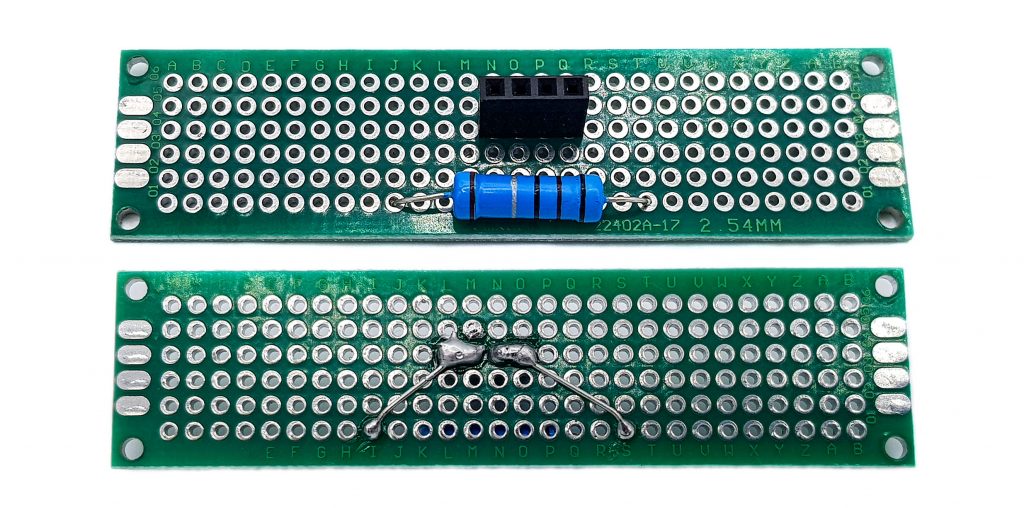
The rest I connected with jumper cables. These appear to have lower contact resistances. In any case, I obtained very reproducible measured values afterwards.
Current sensor based on the ADS1115
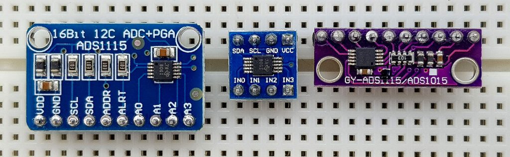
I introduced the ADS1115 in my last post. You can download my library (ADS1115_WE) here from GitHub or directly install it via the library manager of the Arduino IDE. I do not go into the details again, but I would like to mention again that the ADS1115 has an internal amplifier and a resolution of 16 bits. This makes it easy to measure even small voltages.
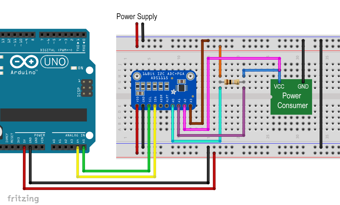
Wiring
I supplied the ADS1115 with the 5 volts of the Arduino UNO. Communication is via I2C. I didn’t need pull-up resistors for the I2C lines, but this can be different with other modules.
I put the shunt in before of the consumer on the high voltage side (high-side configuration). You can, of course, place it behind as well (low-side). I measured the shunt voltage via channels A0 and A1 of the ADS1115. The voltage drop across the consumer (bus voltage) was measured with channels A2 and A3. The power consumption of the consumer can be calculated from the current and the bus voltage.
If, like me, you use a separate power supply for the consumer, then you must ensure a common ground.
Attention: the voltage at the inputs A0 – A4 must not exceed the supply voltage of the ADS1115 by more than 0.3 volts. In this example, that would be 5.3 volts. If the bus voltage is higher, you have to use suitable voltage before the inputs (i.e. here A2 and A3)! Otherwise you will destroy the ADS1115!
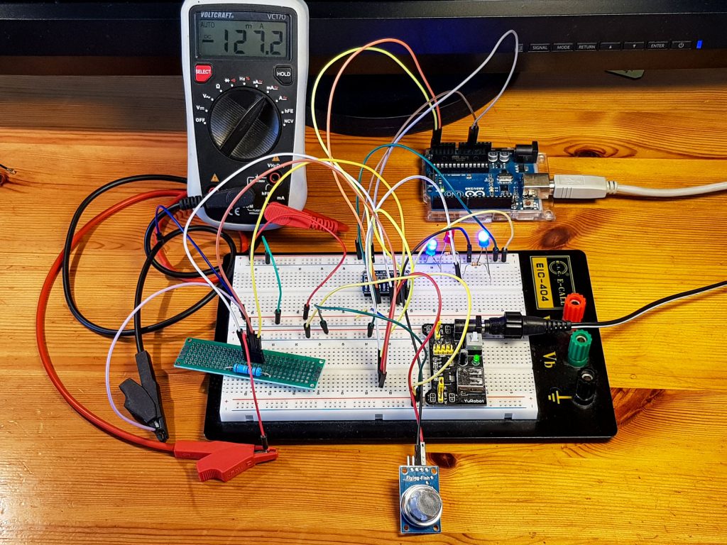
Calibration
Since we cannot take for granted that our shunt has a resistance of exactly 0.1 ohms, the sensor circuit must be calibrated. For this purpose, I used a multimeter for current measurement and determined the shunt voltage for different power consumers. For small currents I have taken LEDs, for slightly larger currents a gas sensor (because I had it just at hand). Here’s what it looked like:
The sketch for calibration
Only the shunt voltage is of interest for calibration. I have chosen the continuous mode and the highest gain (i.e. the smallest voltage range).
#include<ADS1115_WE.h>
#include<Wire.h>
#define I2C_ADDRESS 0x48

ADS1115_WE adc(I2C_ADDRESS);

void setup() {
  Wire.begin();
  Serial.begin(9600);
  if(!adc.init()){
    Serial.println("ADS1115 not connected!");
  }

  /* Set the voltage range of the ADC to adjust the gain
   * Please note that you must not apply more than VDD + 0.3V to the input pins!
   *
   * ADS1115_RANGE_6144  ->  +/- 6144 mV
   * ADS1115_RANGE_4096  ->  +/- 4096 mV
   * ADS1115_RANGE_2048  ->  +/- 2048 mV (default)
   * ADS1115_RANGE_1024  ->  +/- 1024 mV
   * ADS1115_RANGE_0512  ->  +/- 512 mV
   * ADS1115_RANGE_0256  ->  +/- 256 mV
   */
  adc.setVoltageRange_mV(ADS1115_RANGE_0256); //comment line/change paramater to change range

  adc.setCompareChannels(ADS1115_COMP_0_1); //comment line/change paramater to change channel

  adc.setMeasureMode(ADS1115_CONTINUOUS); //comment line/change parameter to change mode

  Serial.println("Stromsensor - Shuntspannung");
  Serial.println();
}

void loop() {
  float voltage = 0.0;
  voltage = adc.getResult_mV(); // alternative: getResult_mV for Millivolt
  Serial.print("Shuntspannung [mV]: ");
  Serial.println(voltage);
  Serial.println("-------------------------------");
  delay(2000);
}
The result of the calibration
The calibration resulted in a nice, straight regression line with only small deviations.


The full current sensor sketch
From shunt voltages and the calibration factor (current / shunt voltage ratio = approx. 9.67) unknown currents can be determined. The power of the consumer is determined by the current I and the bus voltage UBus:
![\[ P_{Consumer}=I\cdot U_{Bus} \]](https://wolles-elektronikkiste.de/wp-content/ql-cache/quicklatex.com-61b00aca8359eddedc89b0261fd8b5a1_l3.png "Rendered by QuickLaTeX.com")
Since the bus voltage is considerably higher than the shunt voltage, these measurements are carried out with different gain factors.
I have chosen the “Single-Shot” mode (i.e. measurement on request). On the one hand, this mode is more energy-efficient, and on the other hand, it ensures via the isBusy() function that no outdated values are read.
#include<ADS1115_WE.h>
#include<Wire.h>
#define I2C_ADDRESS 0x48
ADS1115_WE adc(I2C_ADDRESS);

const float voltageToCurrent = 9.67;

void setup() {
  Wire.begin();
  Serial.begin(9600);
  if(!adc.init()){
    Serial.println("ADS1115 not connected!");
  }

  /* Set the voltage range of the ADC to adjust the gain
   * Please note that you must not apply more than VDD + 0.3V to the input pins!
   *
   * ADS1115_RANGE_6144  ->  +/- 6144 mV
   * ADS1115_RANGE_4096  ->  +/- 4096 mV
   * ADS1115_RANGE_2048  ->  +/- 2048 mV (default)
   * ADS1115_RANGE_1024  ->  +/- 1024 mV
   * ADS1115_RANGE_0512  ->  +/- 512 mV
   * ADS1115_RANGE_0256  ->  +/- 256 mV
   */
  //adc.setVoltageRange_mV(ADS1115_RANGE_6144); //comment line/change paramater to change range

  /* Set the inputs to be compared
   *
   *  ADS1115_COMP_0_1    ->  compares 0 with 1 (default)
   *  ADS1115_COMP_0_3    ->  compares 0 with 3
   *  ADS1115_COMP_1_3    ->  compares 1 with 3
   *  ADS1115_COMP_2_3    ->  compares 2 with 3
   *  ADS1115_COMP_0_GND  ->  compares 0 with GND
   *  ADS1115_COMP_1_GND  ->  compares 1 with GND
   *  ADS1115_COMP_2_GND  ->  compares 2 with GND
   *  ADS1115_COMP_3_GND  ->  compares 3 with GND
   */
  //adc.setCompareChannels(ADS1115_COMP_0_GND); //uncomment if you want to change the default

  Serial.println("Strom- und Leistungssensor mit ADS1115");
  Serial.println();
}

void loop() {
  float voltage = 0.0;

  adc.setCompareChannels(ADS1115_COMP_0_1);
  adc.setVoltageRange_mV(ADS1115_RANGE_0256);
  adc.startSingleMeasurement();
  while(adc.isBusy()){}
  voltage = adc.getResult_mV();
  Serial.print("Shuntspannung [mV]: "); // Shunt voltage
  Serial.println(voltage);

  float current_mA = voltage * voltageToCurrent;
  Serial.print("Busstrom      [mA]: "); // Bus current
  Serial.println(current_mA);

  adc.setVoltageRange_mV(ADS1115_RANGE_6144);
  adc.setCompareChannels(ADS1115_COMP_2_3);
  adc.startSingleMeasurement();
  while(adc.isBusy()){}
  voltage = adc.getResult_V();
  Serial.print("Busspannung    [V]: "); // Bus voltage
  Serial.println(voltage);

  float power_mW = voltage * current_mA;
  Serial.print("Leistung      [mW]: "); // Power
  Serial.println(power_mW);

  Serial.println("-------------------------------");
  delay(2000);
}
Here’s what the output looks like on the serial monitor:
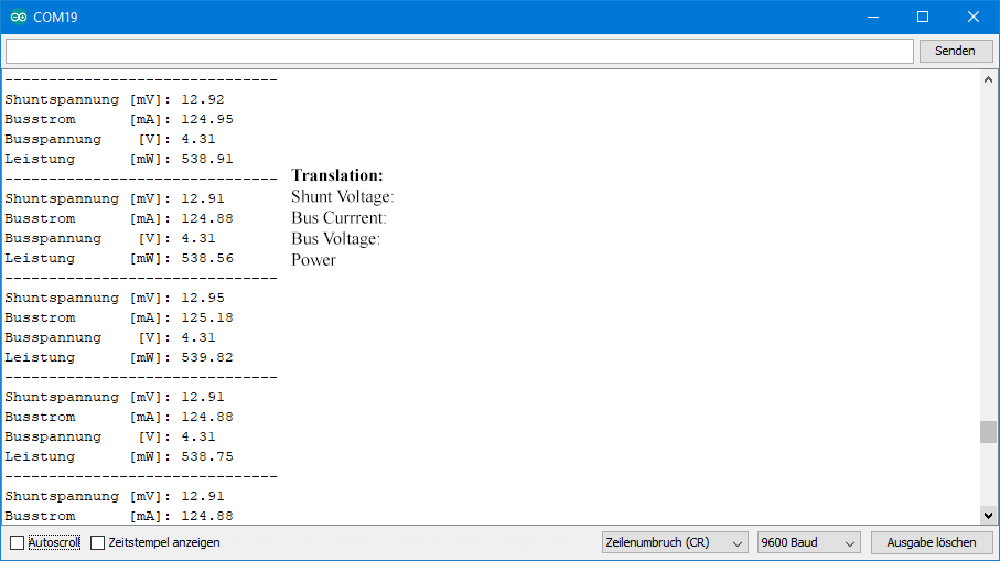
Monitoring of currents
The ADS1115 has an alert pin that you can configure to assert when defined thresholds are exceeded. When you connect the alert pin to an interrupt pin of the Arduino, you can easily monitor currents. With this you have (almost) the full functionality of an INA226 current sensor. You can find information on programming the alert pin in my post about the ADS1115.
Self built current sensor with operational amplifier
The results with shunt and ADS1115 did not look bad, but under the conditions I chose I only used about 10 % of the measuring range of the ADS1115 even at the highest gain. Depending on the resolution you require and the shunt voltages you generate, further amplification may be appropriate. An operational amplifier is ideal for this purpose.
What does an operational amplifier do?
Operational amplifiers (op amps) are extremely versatile components about which books can be written. Therefore, I cannot provide an introduction to this topic within the scope of this article. As an absolute minimum, however, you should know:
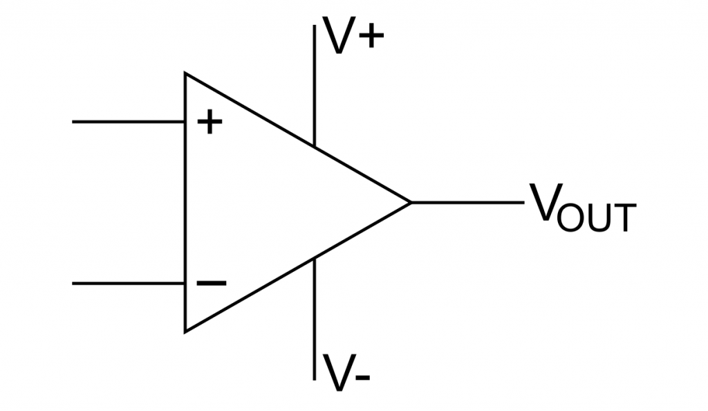
- Op amps are used for voltage amplification.
- They have an inverting (“-“) input, a non-inverting input (“+”) and an output (VOUT).
- The power supply is mostly symmetrical (V+ / V-), but there are also applications with V+ / GND.
- We are dealing here with the latter.
- The op amp only gets its function by connecting it with other components.
- Op amps can be used as inverting or non-inverting amplifiers, as differential amplifiers, integrator amplifiers, etc.
If you are a beginner and want to know more, I recommend this website.
Some op amp examples
Op amps are available in different designs. Mostly you get them as ICs containing several op amps. For this article, the MCP6002, LM358 and the TLV2462 were tried out.
It should be noted up front that I had problems with linearity at low voltages with the TLV2462.

All mentioned representatives have 2 op amps and have the same pinout:

The op amp as differential amplifier
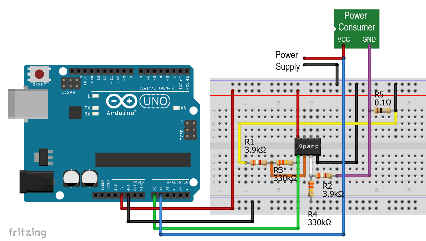
For the amplification of the shunt voltage I used the op amp as a differential amplifier. To amplify the voltage difference between V1 and V2, the op amp is connected as follows:

If R1 is R2 and R3 equals R4, then VOUT is:
![\[ V_{OUT}=\frac{R_3}{R_1}\cdot(V_2-V_1) \]](https://wolles-elektronikkiste.de/wp-content/ql-cache/quicklatex.com-23109455551d2d6bb400633da908f7aa_l3.png "Rendered by QuickLaTeX.com")
If you want to know why, I recommend reading this. As R1 or R2 I have chosen 3.9 kOhm and 330 kOhm as R3 or R4. Thus, the gain factor is theoretically 84.6. With a measuring range of up to 5 volts, shunt voltages of up to 5 V / 84.6 = 59.1 mV can be detected. This in turn corresponds to a maximum current of 591 mA.
For those who are familiar with op amps: I had initially tried to use the op amp as a non-inverting amplifier, as described here. I couldn’t get stable gain factors and the gain factors were much higher than calculated – does anyone have any idea what the issue might be? However, the differential amplifier circuit works very well.
Calibration of the op amp based current sensor
Wiring
For calibration, we have to determine again practically how the increased shunt voltage depends on the current. So weou need a device for voltage measurement and one for current measurement. I used my multimeter for current measurement and the ADS1115 for voltage measurement. Of course, I could have used the A/D converter of the Arduino directly for voltage measurement. However, I was interested in whether there is a linear dependence even for small voltages. And I wanted to use the high resolution of the ADS1115. It would be even easier to use two multimeters. But not everyone has that.
This time, the shunt is positioned behind the consumer (low-side). All components have a common mass.
With a separate power source for the consumer and above all with a separate mass, the high-side configuration can also be realized. For this case, the consumer’s VCC is connected to the mass of the rest of the circuit. The problem, however, is the measurement of the bus voltage, which then is in the negative range.

As a test consumer with different currents, I again chose what was lying around on my table.
Sketch for calibration
The sketch is specific to my type of calibration. If you have multiple multimeters, you don’t need a sketch at all, but measure directly.
#include<ADS1115_WE.h>
#include<Wire.h>
#define I2C_ADDRESS 0x48

ADS1115_WE adc(I2C_ADDRESS);

void setup() {
  Wire.begin();
  Serial.begin(9600);
  if(!adc.init()){
    Serial.println("ADS1115 not connected!");
  }

  /* Set the voltage range of the ADC to adjust the gain
   * Please note that you must not apply more than VDD + 0.3V to the input pins!
   *
   * ADS1115_RANGE_6144  ->  +/- 6144 mV
   * ADS1115_RANGE_4096  ->  +/- 4096 mV
   * ADS1115_RANGE_2048  ->  +/- 2048 mV (default)
   * ADS1115_RANGE_1024  ->  +/- 1024 mV
   * ADS1115_RANGE_0512  ->  +/- 512 mV
   * ADS1115_RANGE_0256  ->  +/- 256 mV
   */
  adc.setVoltageRange_mV(ADS1115_RANGE_6144); //comment line/change paramater to change range

  adc.setCompareChannels(ADS1115_COMP_0_GND); //comment line/change paramater to change channel

  adc.setMeasureMode(ADS1115_CONTINUOUS); //comment line/change paramater to change mode

  Serial.println("Stromsensor - Shuntspannung am Opamp");
  Serial.println();
}

void loop() {
  float voltage = 0.0;
  voltage = adc.getResult_mV();
  Serial.print("Shuntspannung [mV]: ");
  Serial.println(voltage);
  Serial.println("-------------------------------");
  delay(2000);
}
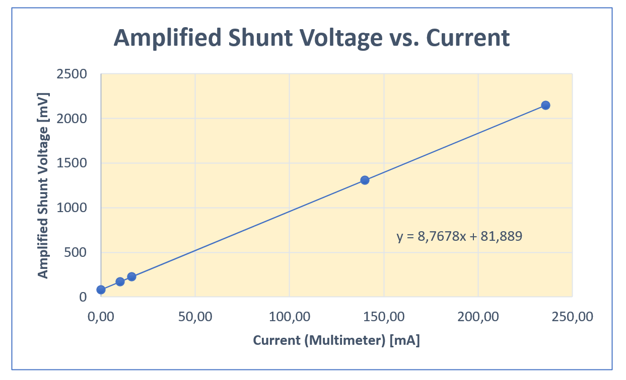
Result of calibration
The measured values were all very close to regression line, at least this applies to the MCP6002 (results shown below) and the LM358. At 0 milliamperes, the amplified shunt voltage should be 0 millivolts. However, the op amps have an offset voltage on VOUT, which must be corrected accordingly.
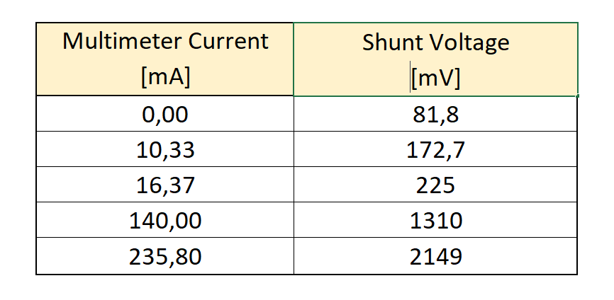
With the TLV2462, the measured values “buckled” towards zero at small voltages. As if the offset voltage was disappearing. I don’t know why – I didn’t want to investigate further.
The complete current sensor
The rest is simple. You can now measure the amplified shunt voltage directly at the Arduino and convert it into the current. The bus voltage is usually so high that you do not need to amplify it.
If you measure the bus voltage at the consumer’s VCC, then there is also a small amount of shunt voltage in it. As a first approximation that is the current, multiplied by 0.1. Last but not least, you can easily calculate the performance.
Here, for completeness, the circuit:
And here’s the full sketch:
const float calibrationFactor = 8.77;
const int offsetValue = 15;
const int opampVOutPin = A0;
const int busAnalogPin = A1;

void setup(){
  Serial.begin(9600);
  Serial.println("Stromsensor mit OpAmp");
}

void loop(){

  float amplifiedShuntVoltage_mV = (analogRead(opampVOutPin) - offsetValue) * 5.0 / 1.024;
  Serial.print("Verstärkte Shuntspannung [mV]: "); // Amplified shunt voltage
  Serial.println(amplifiedShuntVoltage_mV);

  float current_mA = amplifiedShuntVoltage_mV / calibrationFactor;
  Serial.print("Strom [mA]                   : "); // Current
  Serial.println(current_mA);

  // Wir ziehen die Shuntspannung ab, um die reine Busspannung zu haben
  float busVoltage_V = (analogRead(busAnalogPin) * 5.0 / 1024) - (current_mA * 0.1 / 1000);
  Serial.print("Busspannung [V]              : "); // Bus voltage
  Serial.println(busVoltage_V);

  float power_mW = busVoltage_V * current_mA;
  Serial.print("Leistung [mW]                : "); // Power
  Serial.println(power_mW);

  Serial.println("-------------------------------");
  delay(2000);
}
Acknowledgement
I took the already used image of the electric meter for the post image from the Free-Photos section of Pixabay. I owe most of the tools to Clker-Free-Vector-Images. The drilling machine is from Francis Ray on Pixabay.
Why did you choose to add an op-amp to the circuit when the ADS1115 has a programmable gain amplifier built in, and you were using it to good success? You did not explain why you went with this further development of the circuit, it seemed quite good with just the ADS1115 set to maximum gain.
Indeed, the result without opamp did not look bad, at least it was linear. But with the maximum current (~250 mA) I used in my tests, I had a maximum shunt voltage of ~25 mV. That is, even with the highest gain, only about 10% of the positive range of the ADS1115 (+/- 256 mV). Other people might even have lower voltages, depending on shunt size and current. So, the opamp is just an option to get a higher resolution if needed. I will add this in rhe article. Thanks for your comment!
Thank you for your detailed and nice tutorial!
I would like to use your setup, however the current of intrest is very low from 0.1 µA to 10 µA. Could your setup be conviently adapted to handel these lower currents, or would a complete new design be required?
regards
M
Hi M,
to be honest I have no experience with such low currents. For very low currents you either need a big shunt, a high gain and / or a high resolution ADC. A big shunt could have a big impact and a high gain means high noise. So you have “to play” a bit. A suitable high resolution ADC could be the HX711. But still not sure if it would work or if you need something different. Can’t provide a better answer, sorry! Maybe other readers might have an idea?
Regards, Wolfgang
Guten Morgen,
Thank you very much for the fast answer! I will keep an eye open for a sololution or give it a shot with the HX711.
Regards
M