
About this Post
This article is once again about radio, more precisely about LoRa technology using the example of the Ebyte E220, E22 and E32 module series. The example sketches are written for the E220 modules, but can be transferred relatively easily, especially as I list the essential points that need to be adapted. Please forgive me for not having written three versions of each sketch.
Here is an overview of the post:
- Legal – please note
- What is LoRa, LoRaWAN and LPWAN?
- LoRA Modules
- Ebyte LoRa Modules
- Libraries for the Ebyte E220, E22 and E32 Series
- Circuit for the Arduino Nano
- How to make Settings
- Response Container and Response Status
- Transparent Transmission Mode
- Sending and receiving Structures
- Fixed Transmission Mode
- RSSI Received Signal Strength Indicator
- Using Wake On Radio (WOR)
- Waking up the MCU with WOR
- Range Test
- Appendices – Transceiver Sketches with Settings for E220, E22, E32
Legal – please note!
Important to know:
- Radio transmission is regulated by law in almost every country in the world, e.g. regarding the permitted frequencies, the transmission power or the duty cycle (percentage of the actual transmission time).
- Not everything you can buy in your country can be used without restrictions – and some things can’t be used at all!
In Germany, the rules for radio are set by the Federal Network Agency. You can find the relevant details here in the section “Funkanlagen mit geringer Reichweite”. Hobbyists mainly use the frequencies around 433 MHZ, 868 MHz, 915 MHz and 2.4 GHz – but they are not free of restrictions. You are responsible for complying with the regulations in your country.
What is LoRa, LoRaWAN and LPWAN?
If you are dealing with LoRa, you will also come across the terms LoRaWAN and LPWAN. LoRa stands for Long Range, i.e. it is a radio technology for comparatively long distances. LoRa (like Sigfox) belongs to the group of LPWAN radio technologies, which in turn is the abbreviation for Low-Power Wide Area Network. This name thus contains a second characteristic of this technology, namely its low-energy consumption. While LoRa refers to the special radio technology, LoRaWAN is a communication protocol based on it.
I am neither a physicist nor a radio engineer. That’s why I prefer to hold back on explaining exactly how LoRa works. Just this much: It is a special modulation technology that achieves the long-range and low-energy consumption. The data transfer rates are comparatively low.
LoRa Modules
Many different LoRa modules are offered in popular online stores such as Amazon or AliExpress. These also include ready-made solutions, e.g. ESP32-based boards with OLED displays. Originally, I had planned to give a broader overview of common modules and libraries. However, I then realized that the topic is simply too extensive to cover everything in one post. I will therefore initially limit myself to the E220, E22 and E32 series from Ebyte. They are close relatives that can be programmed in almost the same way. I may look at other modules in a later post.
Ebyte LoRa Modules
Overview
Ebyte, more precisely Chengdu Ebyte Electronic Technology Co. Ltd, offers various LoRa modules. If you are looking for specific models, take a look here. I have summarized the most important differences between the module series here:
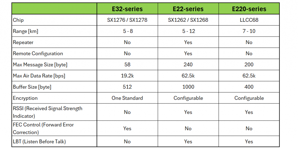
The modules all have the same pinout and are very similar in operation.
An overview of the SX1262, SX1276 and SX1278 chips can be found here. All chips and modules have their advantages and disadvantages.
Naming
The modules are named according to the scheme Eaaa-bbbTccd, e.g. E220-900T22D. The parameters are:
- aaa: the “family name”,
- bbb: represents the radio frequency,
- cc: represents the signal strength in dBm,
- d: stands for the design (DIP or SMD).
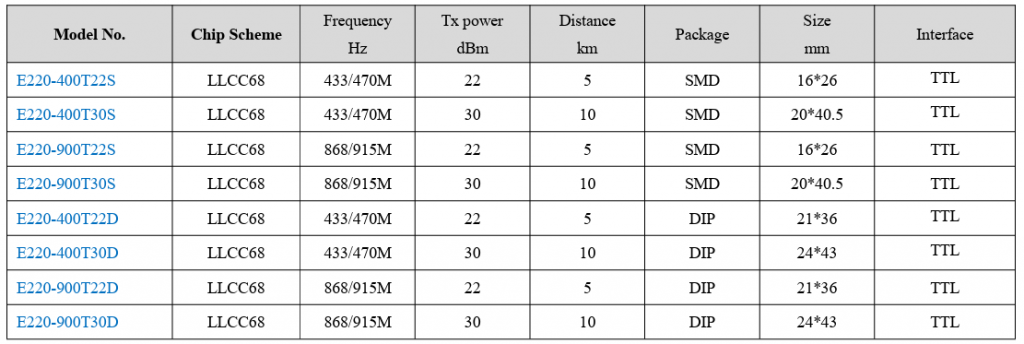
Here, as an example, is an overview of some representatives of the E220 series:
Technical Data (Example E220-900T22D)
You can find data sheets and manuals on the Chengdu Ebyte website. As an example, I have the technical data of the E220-900T22D model for you here:
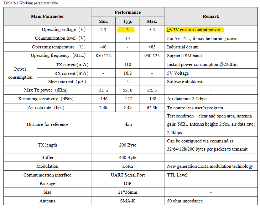
I found a data sheet for the same module elsewhere, but with slightly different information on the optimum voltage supply:
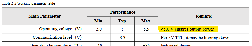
If in doubt, try out whether you achieve better results with 5 volts. However, it is important to note that not all pins can handle 5 volts. For 5 volt MCUs, you should therefore use level shifters or voltage dividers.
Pinout LoRa E220, E22, E32 Series

- GND / VCC: Power supply
- AUX: Indicates the status of the data buffers for sending and receiving and is used for the self-check.
- RX / TX: Serial communication
- M0 / M1 (E220): Control of the four operating modes:
- M0 = LOW, M1 = LOW: Normal mode
- M0 = HIGH, M1 = LOW: WOR Transmitter
- M0 = LOW, M1 = HIGH: WOR Receiver
- M0 = HIGH, M1 = HIGH: Deep sleep
- M0 /M1 (E22): Control of the four operating modes:
- M0 = LOW, M1 = LOW: Normal mode
- M0 = HIGH, M1 = LOW: WOR mode (transmitter/receiver)
- M0 = LOW, M1 = HIGH: Configuration mode
- M0 = HIGH, M1 = HIGH: Deep sleep
- M0 / M1 (E32): Control of the four operating modes:
- M0 = LOW, M1 = LOW: Normal mode
- M0 = HIGH, M1 = LOW: Wake-up mode (transmitter)
- M0 = LOW, M1 = HIGH: Power saving
- M0 = HIGH, M1 = HIGH: Sleep
Libraries for the Ebyte E220, E22 and E32 Series
I selected the libraries of Renzo Mischianti to control the modules. You can download them here from GitHub:
… or install via the library manager of the Arduino IDE.
In addition, the industrious Renzo Mischianti has created a multipart tutorial for each of the module series. Here are the links to the first parts: E220-Tutorial, E22-Tutorial, E32-Tutorial.
My motivation for writing my own article was to summarize things a little more compactly and to compare the module series. However, it is definitely worth taking a look at the tutorials. They offer a lot of additional information, such as example sketches and circuit diagrams for other boards.
The tutorials and libraries for the various series are structured in the same way. This means you can quickly find your way around if you change the module series.
Circuit for the Arduino Nano
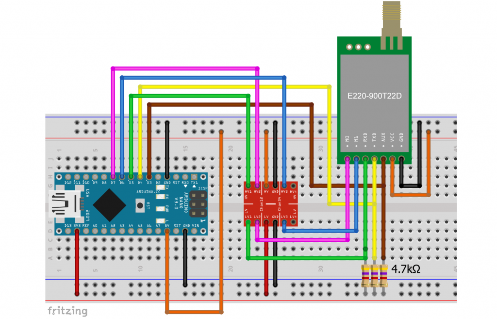
In this article, I use the classic Arduino Nano as the controlling board. I connected it to the E220 module as follows (identical for E22 and E32):

A few comments on this:
- If you do not want to use the WOR (Wake On Radio) or power-down modes, you can connect M0 and M1 to GND.
- In principle, you can also leave AUX unconnected. In this case, the microcontroller does not know when the data transfer is complete, but the library provides a sufficient waiting time.
- When using a 5 volt board, you must use a level shifter or a voltage divider (e.g. 2 kΩ / 1 kΩ) for connecting M0, M1, RX to the board pins.
- AUX, RX and TX require a pull-up resistor.
- Example circuits for other MCU boards can be found in the tutorials by Renzo Mischianti.
- The antennas for the E220-900T22D and E32-433T30D modules I used were special versions with a magnetic base for 868 MHz and 433 MHz. These are available for < €10 in online stores.
This is what my setup looked like on the breadboard:
How to make Settings
Configuration Sketch using the E220 Module Series
The libraries are equipped with separate example sketches for setting up and operating the modules. Use setConfiguration.ino to make the settings, and getConfiguration.ino to query them. These settings are retained even if the power supply is disconnected, provided you select the parameter WRITE_CFG_PWR_DWN_SAVE when saving the configuration (line 62 in the next sketch).
When you open setConfiguration.ino, you may be overwhelmed by its size. However, most of it is commented out, and many things are repeated. The upper section contains various examples of object creation for different boards. The middle section contains ready-made configuration examples that you can easily uncomment. At the end you will find the functions for outputting the settings.
I have reduced setConfiguration.ino (E220 module) to the essentials for use on an Arduino Nano. But I have also added a few lines:
- Lines 1 to 5 are used to output the correct frequency. Just uncomment the line with the correct frequency range.
- Lines 6 and 7 are relevant for selecting the signal strength.
- Line 8 ensures that the settings are output in detail.
- Lines 57 and 58 allow you to encrypt your messages individually.
// #define FREQUENCY_433 // default value without set
// #define FREQUENCY_170
// #define FREQUENCY_470
#define FREQUENCY_868
// #define FREQUENCY_915
// #define E220_22 // default value without set
// #define E220_30 // uncomment in case you use an E220...T30D or E220...T30S
#define LoRa_E220_DEBUG  // for printing the settings
#include "LoRa_E220.h"

SoftwareSerial mySerial(4, 5); // Arduino RX <-- e220 TX, Arduino TX --> e220 RX
LoRa_E220 e220ttl(&mySerial, 3, 7, 6); // AUX M0 M1
// LoRa_E220 e220ttl(4, 5, 3, 7, 6); // alternative function to create the LoRa_E220 object

void printParameters(struct Configuration configuration);
void printModuleInformation(struct ModuleInformation moduleInformation);

void setup() {
  Serial.begin(9600);
  while(!Serial){};
  delay(500);

  Serial.println();


  // Startup all pins and UART
  e220ttl.begin();

  ResponseStructContainer c;
  c = e220ttl.getConfiguration();
  // It's important get configuration pointer before all other operation
  Configuration configuration = *(Configuration*) c.data;
  Serial.println(c.status.getResponseDescription());
  Serial.println(c.status.code);

  printParameters(configuration);

//	----------------------- DEFAULT TRANSPARENT -----------------------
  configuration.ADDL = 0x02;  // Low byte of address
  configuration.ADDH = 0x00; // High byte of address

  configuration.CHAN = 18; // 868 MHz for Exxx-900 modules, choose 23 for Exxx-400 to set 433 MHz

  configuration.SPED.uartBaudRate = UART_BPS_9600; // Serial baud rate
  configuration.SPED.airDataRate = AIR_DATA_RATE_010_24; // Air baud rate
  configuration.SPED.uartParity = MODE_00_8N1; // Parity bit

  configuration.OPTION.subPacketSetting = SPS_200_00; // Packet size
  configuration.OPTION.RSSIAmbientNoise = RSSI_AMBIENT_NOISE_DISABLED; // Need to send special command
  configuration.OPTION.transmissionPower = POWER_22; // Device power

  configuration.TRANSMISSION_MODE.enableRSSI = RSSI_DISABLED; // Enable RSSI info
  configuration.TRANSMISSION_MODE.fixedTransmission = FT_TRANSPARENT_TRANSMISSION; // Transmission mode
  configuration.TRANSMISSION_MODE.enableLBT = LBT_DISABLED; // Check interference
  configuration.TRANSMISSION_MODE.WORPeriod = WOR_2000_011; // WOR timing

  configuration.CRYPT.CRYPT_H = 0x00;  // encryption high byte, default: 0x00
  configuration.CRYPT.CRYPT_L = 0x00;  // encryption low byte, default: 0x00

  /* Set configuration changed and set to hold the configuration; chose
WRITE_CFG_PWR_DWN_LOSE to not save the configuration permanently */
  ResponseStatus rs = e220ttl.setConfiguration(configuration, WRITE_CFG_PWR_DWN_SAVE);
  Serial.println(rs.getResponseDescription());
  Serial.println(rs.code);

  c = e220ttl.getConfiguration();
  // It's important get configuration pointer before all other operation
  configuration = *(Configuration*) c.data;
  Serial.println(c.status.getResponseDescription());
  Serial.println(c.status.code);

  printParameters(configuration);
  c.close();
}

void loop() {

}
void printParameters(struct Configuration configuration) {
  DEBUG_PRINTLN("----------------------------------------");

  DEBUG_PRINT(F("HEAD : "));  DEBUG_PRINT(configuration.COMMAND, HEX);DEBUG_PRINT(" ");DEBUG_PRINT(configuration.STARTING_ADDRESS, HEX);DEBUG_PRINT(" ");DEBUG_PRINTLN(configuration.LENGHT, HEX);
  DEBUG_PRINTLN(F(" "));
  DEBUG_PRINT(F("AddH : "));  DEBUG_PRINTLN(configuration.ADDH, HEX);
  DEBUG_PRINT(F("AddL : "));  DEBUG_PRINTLN(configuration.ADDL, HEX);
  DEBUG_PRINTLN(F(" "));
  DEBUG_PRINT(F("Chan : "));  DEBUG_PRINT(configuration.CHAN, DEC); DEBUG_PRINT(" -> "); DEBUG_PRINTLN(configuration.getChannelDescription());
  DEBUG_PRINTLN(F(" "));
  DEBUG_PRINT(F("SpeedParityBit     : "));  DEBUG_PRINT(configuration.SPED.uartParity, BIN);DEBUG_PRINT(" -> "); DEBUG_PRINTLN(configuration.SPED.getUARTParityDescription());
  DEBUG_PRINT(F("SpeedUARTDatte     : "));  DEBUG_PRINT(configuration.SPED.uartBaudRate, BIN);DEBUG_PRINT(" -> "); DEBUG_PRINTLN(configuration.SPED.getUARTBaudRateDescription());
  DEBUG_PRINT(F("SpeedAirDataRate   : "));  DEBUG_PRINT(configuration.SPED.airDataRate, BIN);DEBUG_PRINT(" -> "); DEBUG_PRINTLN(configuration.SPED.getAirDataRateDescription());
  DEBUG_PRINTLN(F(" "));
  DEBUG_PRINT(F("OptionSubPacketSett: "));  DEBUG_PRINT(configuration.OPTION.subPacketSetting, BIN);DEBUG_PRINT(" -> "); DEBUG_PRINTLN(configuration.OPTION.getSubPacketSetting());
  DEBUG_PRINT(F("OptionTranPower    : "));  DEBUG_PRINT(configuration.OPTION.transmissionPower, BIN);DEBUG_PRINT(" -> "); DEBUG_PRINTLN(configuration.OPTION.getTransmissionPowerDescription());
  DEBUG_PRINT(F("OptionRSSIAmbientNo: "));  DEBUG_PRINT(configuration.OPTION.RSSIAmbientNoise, BIN);DEBUG_PRINT(" -> "); DEBUG_PRINTLN(configuration.OPTION.getRSSIAmbientNoiseEnable());
  DEBUG_PRINTLN(F(" "));
  DEBUG_PRINT(F("TransModeWORPeriod : "));  DEBUG_PRINT(configuration.TRANSMISSION_MODE.WORPeriod, BIN);DEBUG_PRINT(" -> "); DEBUG_PRINTLN(configuration.TRANSMISSION_MODE.getWORPeriodByParamsDescription());
  DEBUG_PRINT(F("TransModeEnableLBT : "));  DEBUG_PRINT(configuration.TRANSMISSION_MODE.enableLBT, BIN);DEBUG_PRINT(" -> "); DEBUG_PRINTLN(configuration.TRANSMISSION_MODE.getLBTEnableByteDescription());
  DEBUG_PRINT(F("TransModeEnableRSSI: "));  DEBUG_PRINT(configuration.TRANSMISSION_MODE.enableRSSI, BIN);DEBUG_PRINT(" -> "); DEBUG_PRINTLN(configuration.TRANSMISSION_MODE.getRSSIEnableByteDescription());
  DEBUG_PRINT(F("TransModeFixedTrans: "));  DEBUG_PRINT(configuration.TRANSMISSION_MODE.fixedTransmission, BIN);DEBUG_PRINT(" -> "); DEBUG_PRINTLN(configuration.TRANSMISSION_MODE.getFixedTransmissionDescription());


  DEBUG_PRINTLN("----------------------------------------");
}
void printModuleInformation(struct ModuleInformation moduleInformation) {
  Serial.println("----------------------------------------");
  DEBUG_PRINT(F("HEAD: "));  DEBUG_PRINT(moduleInformation.COMMAND, HEX);DEBUG_PRINT(" ");DEBUG_PRINT(moduleInformation.STARTING_ADDRESS, HEX);DEBUG_PRINT(" ");DEBUG_PRINTLN(moduleInformation.LENGHT, DEC);

  Serial.print(F("Model no.: "));  Serial.println(moduleInformation.model, HEX);
  Serial.print(F("Version  : "));  Serial.println(moduleInformation.version, HEX);
  Serial.print(F("Features : "));  Serial.println(moduleInformation.features, HEX);
  Serial.println("----------------------------------------");
}
When trying things out, it can be a bit annoying to adjust the settings via a separate sketch, even if this saves resources. Perhaps you would prefer to make the settings directly in the sketches that you also use for control? And perhaps you would like to have an overview of all the setting options? Then take a look at Appendix 1 for the E220 series.
Configuration Sketches for the E22 and E32 Series
In Appendix 2 and Appendix 3 you will find the counterparts to Appendix 1 for the E22 and E32 series respectively. The sketches also provide a good overview of the differences between the three module series.
Settings in Detail
Address and Channel (configuration)
Each LoRa module has an address, which is made up of the higher byte ADDH and the lower byte ADDL. This allows you to set 65536 addresses. The address is assigned via configuration.ADDL = ... or configuration.ADDH = ....
The modules I tested cover the frequencies 850 – 930 MHz and 410 to 493 MHz. Fine adjustment is made via the channel. The formula for the frequency ν is
![\[ \nu_{Exxx-900}\; \text{[MHz]} = 850.125\ + \text{\it{CHANNEL}} \]](https://wolles-elektronikkiste.de/wp-content/ql-cache/quicklatex.com-d9f59811c2590eac059781d3714981cd_l3.png "Rendered by QuickLaTeX.com")
![\[ \nu_{Exxx-400}\; \text{[MHz]} = 410.125 + \text{\it{CHANNEL}} \]](https://wolles-elektronikkiste.de/wp-content/ql-cache/quicklatex.com-2baff5daf0d7fc991550d9b45a8122bb_l3.png "Rendered by QuickLaTeX.com")
For the Exxx-900 modules, use configuration.CHAN = 18 to set the frequency to 868.125 MHz. With the Exxx-400 models, you set 433.125 MHz with configuration.CHAN = 23.
There is a certain risk that you will transmit on a frequency that is not permitted in your country if you make the wrong selection. I’m just saying.
A check with a tinySA Spectrum Analyzer showed a good match with the target frequency within the accuracy of this device. Here is the result for channels 0, 18 and 80 of an E220-900T22D module:
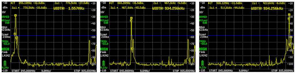
The principle of channel setting is identical for all modules.
Transmission Rate and Options (configuration.SPED)
You can set the following parameters for UART communication and data transmission over the air (example E220):
- uartBaudRate: Baud rate UART_BPS_xxx
- xxx = 1200, 2400, 4800, 9600, 19200, 38400, 57600, 115200
- airDataRate: Data rate for radio transmission AIR_DATA_RATE_xxx
- AIR_DATA_RATE_010_24: 2.4 kbit/s (default)
- AIR_DATA_RATE_011_48: 4.8 kbit/s
- AIR_DATA_RATE_100_96: 9.6 kbit/s
- AIR_DATA_RATE_101_192: 19.2 kbit/s
- AIR_DATA_RATE_110_384: 38.4 kbit/s
- AIR_DATA_RATE_111_625: 62.5 kbit/s
- uartParity: Parity MODE_xxx;
- MODE_00_8N1: none (default)
- MODE_01_8O1: odd
- MODE_10_8E1: even
The options for the airDataRate differ for the E22 and 32 series. See Appendix 2 and 3.
Regarding the data rate via radio: the lower the data rate, the higher the maximum range.
Further Transmission Options (configuration.OPTION)
Further options (example E220):
- subPacketSetting: Maximum data packet size, i.e. the maximum length of your message that you can send continuously in one piece.
- SPS_200_00: 200 bytes
- SPS_128_01: 128 bytes
- SPS_064_10: 64 bytes
- PLC_032_11: 32 bytes
- RSSIAmbientNoise: RSSI (Received Signal Strength Indicator) Ambient Noise enable
- RSSI_AMBIENT_NOISE_DISABLED: Function is switched off
- RSSI_AMBIENT_NOISE_ENABLED: Function is switched on
- transmissionPower: Transmission power POWER_xx with xx = power in dbm. The setting options depend on the model you are using.
- xx for E220….22D: 22, 17, 13, 10
- xx for E220….30D: 30, 27, 24, 21
The subPacketSetting and transmissionPower settings differ for the E22 and E32 series (see Appendix 2 and 3). RSSIAmbientNoise is not available on the E32 module.
Mode Settings (configuration.TRANSMISSION_MODE)
I will come back to some of these settings later. Here are the options for the E220 series:
- enableRSSI: Signal strength information (Received Signal Strength Indication)
- RSSI_DISABLED: disabled
- RSSI_ENABLED: enabled
- fixedTransmission: Transmission mode
- FT_FIXED_TRANSMISSION: Transmission to a specific address / channel.
- FT_TRANSPARENT_TRANSMISSION: Transmission to all modules with identical address and channel.
- enableLBT: LBT (Listen Before Talk) is a function that causes the module to wait up to two seconds for a favorable moment (with low interference) before transmitting.
- LBT_DISABLED: Function disabled
- LBT_ENABLED: Function enabled
- WORPeriod: WOR (Wake On Radio) period WOR_xxx_yyy with xxx = wake-up period in milliseconds
- xxx_yyy = 500_000, 1000_001, 1500_010, 2000_011, 2500_100, 3000_101, 3500_110, 4000_111
The WORPeriod parameter needs a little more explanation. This is the period after which the receiver wakes up to check whether a message is coming. Of course, the sender does not know when the receiver is awake and therefore sends a “preamble” with the length of the wake-up period. The WOR receiver then remains awake until the actual message is received. For this reason, the WOR Receiver and the WOR Transmitter must have the same WORPeriod set.
The WORPeriod is called wirelessWakeUpTime when using the E32 series. The selectable periods are also different. The enableRSSI and enableLBT settings are not available on the E32 modules.
Encryption (configuration.CRYPT)
All modules encrypt the messages. However, only the E22 and E220 series modules allow individual encryption. To do this, you define values for the two bytes CRYPT_H and CRYPT_L. The setting must, of course, be identical for the transmitter and receiver. A fixed encryption setting is used on the E32.
Response Container and Response Status
Before we finally come to the pratical part, I need to explain two structures defined in the library, namely ResponseContainer and ResponseStatus. They contain information about the incoming and outgoing messages.
The ResponseContainer contains the actual message data, the signal strength value rssi, and the ResponseStatus status.
struct ResponseContainer {
  String data;
  byte rssi; // only E22 and E220 series!
  ResponseStatus status;
};
The ResponseStatus is also a structure. It contains the error code code and the function getResponseDescription(), which returns a string that translates the code comprehensibly. For example, error code 1 (E220_SUCCESS) means “Success”.
struct ResponseStatus {
  Status code;
  String getResponseDescription() {
    return getResponseDescriptionByParams(this->code);
  }
};
Transparent Transmission Mode
But now to the first sketch. We allow several (at least two) modules to communicate with each other in “Transparent Transmission Mode”. In this mode, you can reach all LoRa modules that have the same address and channel set:
To try out the transparent mode, you should not normally need to make any changes to the settings. However, if you have problems, set the modules to the correct state with setConfiguration_modified.ino.
Then upload the lora_transparent.ino sketch to the microcontroller boards. You may need to adjust lines 3 and 4 for your boards. Take a look at the original example sketches in the library – there are many ready-made settings for different boards.
In most examples, we need a separate serial monitor for each board. With the old Arduino IDE 1.x, this was easy by simply calling up the IDE several times, i.e. creating several instances and selecting a separate serial port for each instance. The IDE 2.x does not seem to allow multiple instances. You can help yourself by saving the sketch under different names, opening the versions, and then setting a separate port for each sketch.
#include "LoRa_E220.h"

SoftwareSerial mySerial(4,5);
LoRa_E220 e220ttl(&mySerial, 3, 7, 6); // AUX M0 M1

void setup() {
  Serial.begin(9600);
  delay(500);

  Serial.println("Hi, I'm going to send message!");

  // Startup all pins and UARTD
  e220ttl.begin();

  // Send message
  ResponseStatus rs = e220ttl.sendMessage("Hello, world?");
  // Check if there is some problem of successfully send
  Serial.println(rs.getResponseDescription());
}

void loop() {
    // If something available
  if (e220ttl.available()>1) {
      // read the String message
    ResponseContainer rc = e220ttl.receiveMessage();
    // Is something goes wrong print error
    if (rc.status.code!=1){
        Serial.println(rc.status.getResponseDescription());
    }else{
        // Print the data received
        Serial.println(rc.data);
    }
  }
  if (Serial.available()) {
      String input = Serial.readString();
      e220ttl.sendMessage(input);
  }
}
Apart from the library to be integrated and the object creation (line 4), the sketch works in the same way with the E22 and E32 boards.
Explanations for lora_transparent.ino
First create the object e220ttl and initialize your module with e220ttl.begin().
You send messages using sendMessage(). As you can see, you do not enter an address or channel in transparent mode. The module automatically sends to the modules with the same settings. The return value of sendMessage() is a structure of the type ResponseStatus, which I explained above. You can get a readable translation of the status code with getResponseDescription(). Ideally, this is “Success”. However, “Success” only means that the message was sent successfully and not that it was received.
You can check whether a message has been received on the receiver side with e220ttl.available(). You are reading the message using receiveMessage(). More precisely, receiveMessage() returns a structure of the type ResponseContainer, which contains the actual message in the element data.
The ResponseContainer “rc” in turn contains the ResponseStatus “rc.status”. You check with
if (rc.status.code != 1) {....
whether an error has occurred. Perhaps the variant
if (rc.status.getResponseDescription() = "Success") {...
would be a little easier to understand, but I wanted to stay close to the original library sketches.
If everything is OK, the message is displayed, if not, the corresponding error message appears.
Use if (Serial.available(){... to check whether an input has been made via the serial monitor. If this is the case, the entry is read and sent.
Output lora_transparent.ino
I used three modules. Below, you can see the output of the first activated module. The two “Hello, world?” messages were sent via the setup of the other modules. I sent the two other messages “manually” from the other modules by entering them in the serial monitor.

Sending and receiving Structures
In most cases, you probably do not want to transmit character strings, but data, such as that of a weather station. In the following example, we send the humidity (integer), the temperature (float) and the rain status (bool) every five seconds. To send this data as a “package”, we define the structure weatherData.
For this example, we will remain in transparent mode. The two sketches for the transmitter and receiver only need to be changed for the E22 and E32 modules regarding the library to be integrated and the object creation.
Transmitter
The sketch for the transmitter should be largely self-explanatory:
#include "LoRa_E220.h"
SoftwareSerial mySerial(4,5);
LoRa_E220 e220ttl(&mySerial, 3, 7, 6); // AUX M0 M1
struct weatherData {
int humidity;
float temperature;
bool rain;
};
weatherData currentWeather = {50, 20.0, false};
void setup() {
Serial.begin(9600);
delay(500);
Serial.println("Hi, I'm going to send message!");
// Startup all pins and UARTD
e220ttl.begin();
// Send message
ResponseStatus rs = e220ttl.sendMessage("Hello, world?");
// Check if there is some problem of successfully send
Serial.println(rs.getResponseDescription());
}
void loop() {
static unsigned long lastSend = millis();
if(millis() - lastSend > 5000){
currentWeather.humidity = 30;
currentWeather.temperature = 23.7;
currentWeather.rain = false;
e220ttl.sendMessage(¤tWeather, sizeof(currentWeather));
lastSend = millis();
}
}
Regarding the sending process, the only difference to the previous sketch is that we do not pass sendMessage() a string, but a structure (as reference using “&”) and the size of the structure.
Receiver
To be able to process the structure to be received, we use the structureur ResponseStructContainer instead of ResponseContainer, which is defined as follows:
struct ResponseStructContainer {
  void *data;
  byte rssi;
  ResponseStatus status;
  void close() {
    free(this->data);
  }
};
The data type void* is an untyped pointer that many readers may not be familiar with. In contrast to the usual pointers such as int*, its meaning, i.e. the data type, must first be assigned to it.
Here is the sketch:
#include "LoRa_E220.h"

SoftwareSerial mySerial(4,5);
LoRa_E220 e220ttl(&mySerial, 3, 7, 6); // AUX M0 M1

struct weatherData {
  int humidity;
  float temperature;
  bool rain;
};

void setup() {
  Serial.begin(9600);
  delay(500);

  Serial.println("Hi, waiting for weather data...");
  // Startup all pins and UARTD
  e220ttl.begin();
}

void loop() {
  if (e220ttl.available()>1) {
      // read the String message
    ResponseStructContainer rsc = e220ttl.receiveMessage(sizeof(weatherData));
    weatherData currentWeather = *(weatherData*) rsc.data;
    Serial.print("Humidity     [%]: ");
    Serial.println(currentWeather.humidity);
    Serial.print("Temperature [°C]: ");
    Serial.println(currentWeather.temperature);
    Serial.print("Rain            : ");
    if(currentWeather.rain){
      Serial.println("yes");
    }
    else{
      Serial.println("no");
    }
    Serial.println();
  }
}
The line:
ResponseStructContainer rsc = e220ttl.receiveMessage(sizeof(weatherData));
reads the received message and saves it in ResponseStructContainer “rsc”. Please note that we must pass the size of the expected data packet to receiveMessage().
The actual data is stored as data type void* in rsc.data. To be able to do something with this, we cast the data type void* into a pointer with (weatherData*), which points to the structure of type weatherData. To save the data in the structure currentWeather, we have to dereference the pointer with another *. So:
weatherData currentWeather = *(weatherData*) rsc.data;
The output is still missing. It’s a bit boring, of course, because we always send the same data. But this is only about the principle.
Fixed Transmission Mode
You set the fixed transmission mode by changing the line
configuration.TRANSMISSION_MODE.fixedTransmission = FT_TRANSPARENT_TRANSMISSION;
to:
configuration.TRANSMISSION_MODE.fixedTransmission = FT_FIXED_TRANSMISSION;
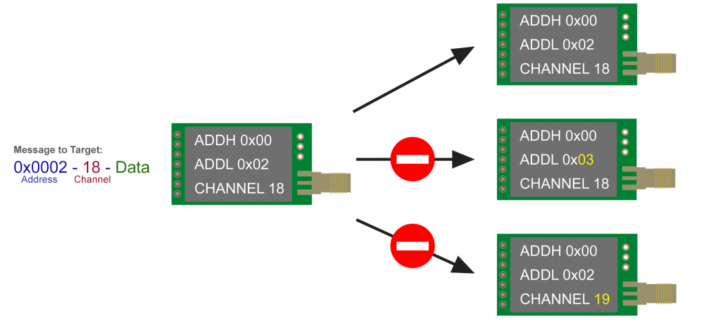
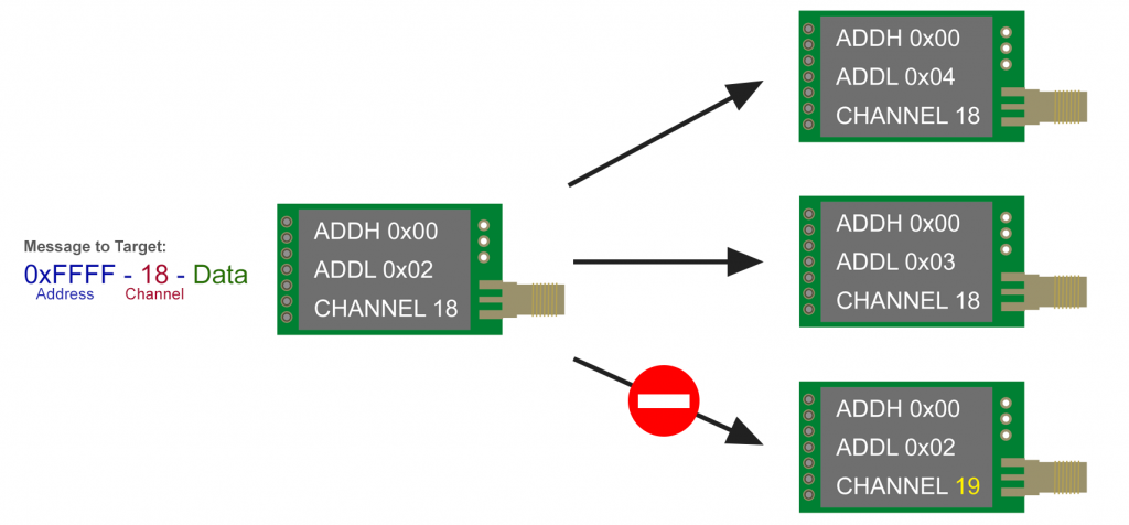
There are two options for sending messages in fixed transmission mode:
- Exclusive transmission to the modules with a specific address on a specific channel:
- Function:
sendFixedMessage(ADDH, ADDL, channel, message); - The transmitting module itself may have a different address and a different channel set.
- Function:
- Sending to all modules on a specific channel, regardless of their address (“broadcasting”):
- Function:
sendBroadcastFixedMessage(channel, message)- which corresponds to:
sendFixedMessage(0xFF, 0xFF, channel, message), as 0xFFFF is the broadcasting address.
- which corresponds to:
- The transmitting module may also have a different channel set here.
- Function:
I have two diagrams to illustrate this. Here first for sending to a specific address:
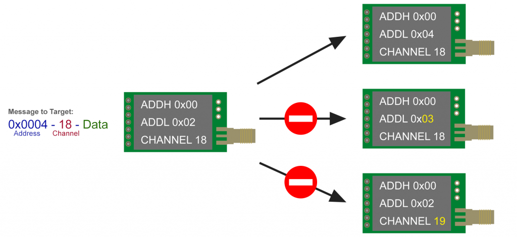
And here is the diagram for broadcasting in fixed transmission mode:
Example Sketch Fixed Transmission Mode
To test the fixed transmission mode, I used three modules with the following settings:
- ADDH = 0x00, ADDL = 0x01, Channel = 18
- ADDH = 0x00, ADDL = 0x02, Channel = 18
- ADDH = 0x00, ADDL = 0x03, Channel = 18
I have uploaded the following sketch to the three controlling Arduino boards, whereby I have only adapted the “greeting” in line 16 and the switch construction from line 38.
The sketch allows messages entered via the serial monitor to be sent to specific addresses (input: “x,message” with x = 1,2,3) or to all modules via broadcasting (input: “18,message”).
The sketch only needs to be adapted for use on E22 and E32 modules regarding the library and object creation.
#include "LoRa_E220.h"

SoftwareSerial mySerial(4, 5); // Arduino RX <-- e220 TX, Arduino TX --> e220 RX
LoRa_E220 e220ttl(&mySerial, 3, 7, 6); // AUX M0 M1

void setup() {
  Serial.begin(9600);
  delay(500);

  Serial.println("Hi, I'm going to send message!");

  // Startup all pins and UART
  e220ttl.begin();

  // Send message
  ResponseStatus rs = e220ttl.sendBroadcastFixedMessage(18,"Hi to all receivers! This is no. 1"); // adjust
  // Check If there is some problem of successfully send
  Serial.println(rs.getResponseDescription());
}

void loop() {
    // If something available
  if (e220ttl.available()>1) {
      // read the String message
    ResponseContainer rc = e220ttl.receiveMessage();
    // Is something goes wrong print error
    if (rc.status.code!=1){
        Serial.println(rc.status.getResponseDescription());
    }else{
        // Print the data received
        Serial.println(rc.data);
    }
  }
  if (Serial.available()) {
    int addr = Serial.parseInt();
    String input = Serial.readString();
    input = input.substring(input.indexOf(",")+1);
    switch(addr){
      case 2:
        e220ttl.sendFixedMessage(0,2,18,input);
        break;
      case 3:
        e220ttl.sendFixedMessage(0,3,18,input);
        break;
      case 18:
        e220ttl.sendBroadcastFixedMessage(18,input);
        break;
      default:
        e220ttl.sendBroadcastFixedMessage(18,input);
    }
  }
}
Here is the output of module 3 (ADDL = 3). To receive the greetings (“Hi to all receivers! …”) from the other modules, it had to be initialized before them.
Of course, structures can also be sent in fixed transmission mode. However, I try to keep my examples simple and limit them to the relevant topic.
RSSI Received Signal Strength Indicator
As the RSSI function is not available on the E32 modules, this section only applies to the E22 and E220 modules.
The RSSI is a dimensionless number of the byte datatype that tells you how strong the received signal was. The number cannot be directly translated into a signal strength in dBm. To read out the RSSI, simply replace receiveMessage() with ReceiveMessageRSSI() on the receiver side, for example:
ResponseContainer rc = e220ttl.receiveMessageRSSI();
Here is an example sketch:
#include "LoRa_E220.h"

SoftwareSerial mySerial(4,5);
LoRa_E220 e220ttl(&mySerial, 3, 7, 6); // AUX M0 M1

void setup() {
  Serial.begin(9600);
  delay(500);

  Serial.println("Hi, I'm going to send message!");

  // Startup all pins and UART
  e220ttl.begin();

  // Send message
  ResponseStatus rs = e220ttl.sendFixedMessage(0,2,18,"Hello, world?");
  // Check If there is some problem of successfully send
  Serial.println(rs.getResponseDescription());
}

void loop() {
    // If something available
  if (e220ttl.available()>1) {
      // read the String message
    ResponseContainer rc = e220ttl.receiveMessageRSSI();
    // Is something goes wrong print error
    if (rc.status.code!=1){
        Serial.println(rc.status.getResponseDescription());
    }else{
        // Print the data received
        String output = rc.data;
        byte rssiVal =  rc.rssi;
        Serial.println(rc.data);
        Serial.print("RSSI: ");
        Serial.println(rc.rssi);
    }
  }
  if (Serial.available()) {
      String input = Serial.readString();
      e220ttl.sendFixedMessage(0,2,18,input);
  }
}
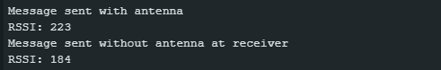
For the following receiver output, I placed two modules on my desk and sent two messages. For the first message, I used antennas for both modules. Before sending the second message, I disconnected the antenna from the receiving module. As you can see, the received signal strength has dropped accordingly. As you can also see, the RSSI is not a measure of the actual signal strength, as this is the same in both cases.
Using Wake On Radio (WOR)
The power consumption of the LoRa module series E220, E22 and E32 can be significantly reduced if they are operated in WOR mode (“Wake On Radio”). As mentioned above, the transmitter and receiver must have the same WOR period set.
WOR Transmitter
The only additional setting you need to make on the transmitter side is the WOR transmitter mode:
e220ttl.setMode(MODE_1_WOR_TRANSMITTER);
You do this directly in your application sketch, i.e. not via the configuration sketch. Despite its role as a WOR transmitter, the module can still receive messages.
Here is the sketch for the WOR transmitter:
#include "LoRa_E220.h"

SoftwareSerial mySerial(4, 5); // Arduino RX <-- e220 TX, Arduino TX --> e220 RX
LoRa_E220 e220ttl(&mySerial, 3, 7, 6); // AUX M0 M1

void setup() {
  Serial.begin(9600);
  delay(500);

  Serial.println("Hi, I'm going to send a WOR message!");

  e220ttl.begin();
  e220ttl.setMode(MODE_1_WOR_TRANSMITTER);

  // Send message
  ResponseStatus rs = e220ttl.sendFixedMessage(0,2,18,"Hello, world? WOR!");
  // Check If there is some problem of successfully send
  Serial.println(rs.getResponseDescription());
}

void loop() {
    // If something available
  if (e220ttl.available()>1) {
      // read the String message
    ResponseContainer rc = e220ttl.receiveMessage();
    // Is something goes wrong print error
    if (rc.status.code!=1){
       Serial.println(rc.status.getResponseDescription());
    }else{
        // Print the data received
        Serial.println(rc.data);
    }
  }
  if (Serial.available()) {
      String input = Serial.readString();
      e220ttl.sendFixedMessage(0,2,18,input);
  }
}
The output is still missing. As you can see below, the transmitter receives a confirmation of receipt. This is not a feature of WOR mode, but a feature of the receiver sketch, to which we will come soon.

Instead of setMode(MODE_1_WOR_TRANSMITTER) you use setMode(MODE_1_WAKE_UP) for the E32 modules. For the E22 modules, set mode MODE_1_WOR in the sketch and define the role as WOR transmitter via the configuration sketch.
WOR Receiver
You can set the WOR receiver mode as follows:
e220ttl.setMode(MODE_2_WOR_RECEIVER);
To be able to send back the confirmation of receipt, you must switch the receiver to normal mode using e220ttl.setMode(MODE_0_NORMAL);.
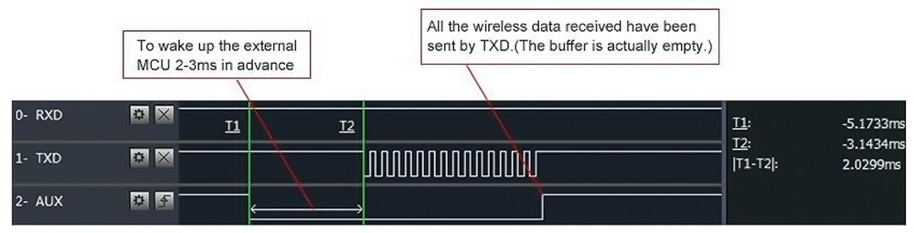
You do not necessarily need the interrupt inserted here, which is triggered by the falling edge of the AUX pin. It is only used to announce the output of the incoming message via the TX pin. Here is the diagram of the behavior of the AUX pin and TX pin:
#include "LoRa_E220.h"
#define AUX_PIN 3
volatile bool interruptExecuted = false;

SoftwareSerial mySerial(4, 5); // Arduino RX <-- e220 TX, Arduino TX --> e220 RX
LoRa_E220 e220ttl(&mySerial, AUX_PIN, 7, 6); // AUX M0 M1


void wakeUp() {
  interruptExecuted = true;
  //detachInterrupt(digitalPinToInterrupt(AUX_PIN));
}

void setup() {
  Serial.begin(9600);
  delay(500);

  e220ttl.begin();
  e220ttl.setMode(MODE_2_WOR_RECEIVER);

  Serial.println("Start sleep!");
  delay(100);
  attachInterrupt(digitalPinToInterrupt(AUX_PIN), wakeUp, FALLING);
}

void loop() {
  //  If something available
  if (e220ttl.available()>1) {
    Serial.println("Message arrived");
      // read the String message
    ResponseContainer rc = e220ttl.receiveMessage();

    String message = rc.data;
    //Serial.println(rc.status.getResponseDescription());
    Serial.println(message);

    e220ttl.setMode(MODE_0_NORMAL); // change to normal mode
    delay(1000);

    e220ttl.sendFixedMessage(0, 1, 18, "We have received the message!");
    e220ttl.setMode(MODE_2_WOR_RECEIVER); // change back to WOR receiver mode
    interruptExecuted = false;
  }

  if(interruptExecuted) {
    Serial.println("WakeUp Callback, AUX pin go LOW and start receive message!");
    Serial.flush();
    //attachInterrupt(digitalPinToInterrupt(AUX_PIN), wakeUp, FALLING);
    interruptExecuted = false;
  }
}
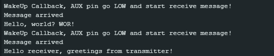
And here is the output:
Instead of setMode(MODE_2_WOR_RECEIVER) you use setMode(MODE_2_POWER_SAVING) for the E32 modules. For the E22 modules, set the mode MODE_1_WOR in the sketch and define the role as WOR receiver before as a permanent setting via setConfiguration.ino.
Waking up the MCU with WOR
Since the AUX pin goes LOW after / while receiving the message and before outputting it to the microcontroller, this signal can be used to wake up not only the LoRa module but also a sleeping microcontroller via an external interrupt.
Unfortunately, the lead time between the falling edge of the AUX pin and the start of transmission via the TX pin cannot be set (at least I have not found a way to do this). Two to three milliseconds may be too little time, for example, to bring an ESP32 back from deep sleep. On the Arduino Nano, I noticed that at least the first character of the transmitted message was missing. A pragmatic solution, at least for my Arduino Nano configuration, would be to prefix the message with a few dummy characters that can be sacrificed.
I have chosen an alternative solution in my example, namely we first send a “wake-up call”. Before the actual message goes out, we send the transmitter a confirmation that the receiver is awake.
Here is the transmitter sketch:
Transmitter Side
#include "LoRa_E220.h"

SoftwareSerial mySerial(4, 5); // Arduino RX <-- e220 TX, Arduino TX --> e220 RX
LoRa_E220 e220ttl(&mySerial, 3, 7, 6); // AUX M0 M1

void setup() {
  Serial.begin(9600);
  delay(500);
  Serial.println("Hello, starting now. Type in a message.");

  e220ttl.begin();
  e220ttl.setMode(MODE_1_WOR_TRANSMITTER);
}

void loop() {
  if (Serial.available()) {
    String input = Serial.readString();
    e220ttl.sendFixedMessage(0,2,18,"......wake up!!"); // wake up call
    e220ttl.setMode(MODE_0_NORMAL); // change to normal mode
    delay(100); // give time for the receiver to wake up

    while(e220ttl.available()<= 1); // wait for confirmation
    ResponseContainer rc = e220ttl.receiveMessage(); // receive message
    rc.status.getResponseDescription();
    Serial.println(rc.data);

    e220ttl.sendFixedMessage(0,2,18,input); // send the actual message
    e220ttl.setMode(MODE_1_WOR_TRANSMITTER); // change back to WOR transmitter mode
  }
}
And here is the unsurprising output:
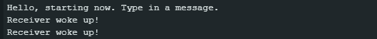
Here too – apart from the general adjustments – you must make the setting setMode(MODE_1_WAKE_UP) instead of setMode(MODE_1_WOR_TRANSMITTER) for the E32 modules. For the E22 modules, set the mode MODE_1_WOR in the sketch and define the role as WOR transmitter as a permanent setting.
Receiver Side
The sleep modes of microcontrollers are hardware-specific. I have written an article about the sleep modes of AVR microcontrollers here. If you are not using an AVR-based microcontroller board, you will have to adapt the sketch accordingly.
#include "LoRa_E220.h"
#include <avr/sleep.h>

#define AUX_PIN 3

SoftwareSerial mySerial(4, 5); // Arduino RX <-- e220 TX, Arduino TX --> e220 RX
LoRa_E220 e220ttl(&mySerial, AUX_PIN, 7, 6); // AUX M0 M1

void wakeUp() {
  delay(0); // add code if you want
}


void setup() {
  Serial.begin(9600);
  delay(500);

  // Startup all pins and UART
  e220ttl.begin();

  e220ttl.setMode(MODE_2_WOR_RECEIVER);

  Serial.println("Start sleep!");
  delay(100);
  attachInterrupt(digitalPinToInterrupt(AUX_PIN), wakeUp, FALLING);
  set_sleep_mode(SLEEP_MODE_PWR_DOWN); // define sleep mode
}


void loop() {
  sleep_mode(); // set MCU (Arduino Nano) to sleep
  delay(10);
  if (e220ttl.available()>1) {  // wait for wake up
    ResponseContainer rc = e220ttl.receiveMessage();
    String message = rc.data;
    Serial.println(message);

    e220ttl.setMode(MODE_0_NORMAL);
    delay(200);
    e220ttl.sendFixedMessage(0, 1, 18, "Receiver woke up!");
    delay(100);

    while(e220ttl.available()<= 1); // wait for second message
    rc = e220ttl.receiveMessage();
    message = rc.data;
    Serial.println(message);
    Serial.flush();
    e220ttl.setMode(MODE_2_WOR_RECEIVER);
  }
}
Here is the output:
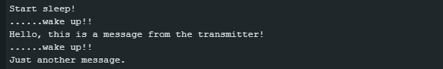
If you change the WORPeriod, you must change the delays in the sketches so that the interaction works.
For E32 modules, among other things, setMode(MODE_2_WOR_RECEIVER) must be replaced by setMode(MODE_2_POWER_SAVING). For the E22 modules, set the mode MODE_1_WOR in the sketch and define the role as WOR receiver as a permanent setting.
Range Test
I carried out a range test with the E220-900T22D module. According to the data sheet, the range is up to 5 km, but only if there is a clear line of sight between the modules, which is rather rare at this distance.
I selected the highest transmission power of 22 dBm (one-off test that exceeds the allowed limits in Germany) and the lowest data rate because this should provide the greatest range. The antenna used was an 868 MHz antenna. The Arduino was supplied with power via a 9 V lithium battery. Measures for voltage stabilization such as additional capacitors were not used.
Here is the receiver unit:
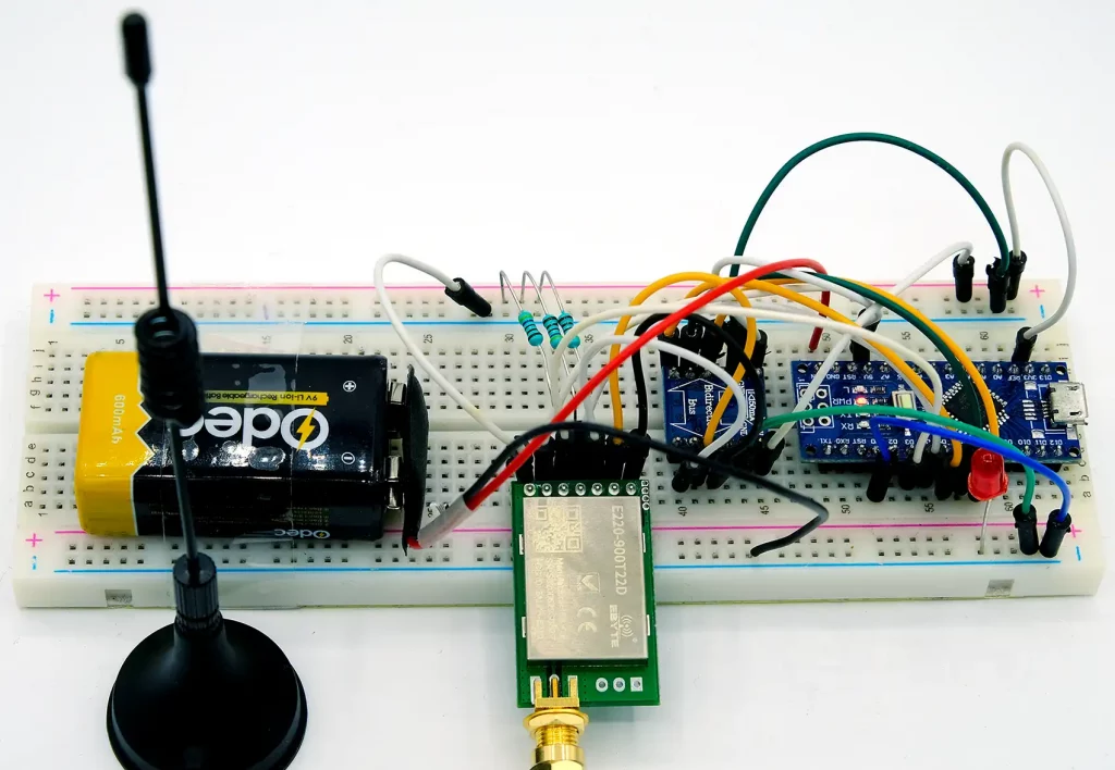
The transmitter has sent a message every 5 seconds:
#include "LoRa_E220.h"

SoftwareSerial mySerial(4, 5); // Arduino RX <-- e220 TX, Arduino TX --> e220 RX
LoRa_E220 e220ttl(&mySerial, 3, 7, 6); // AUX M0 M1

void setup() {
  Serial.begin(9600);
  delay(500);

  Serial.println("Hi, I'm going to send message!");

  // Startup all pins and UART
  e220ttl.begin();

  // Send message
  ResponseStatus rs = e220ttl.sendFixedMessage(0,2,18,"Hi to receiver!"); // adjust
  // Check If there is some problem of successfully send
  Serial.println(rs.getResponseDescription());
  delay(2000);
}

void loop() {
  // If something available
  static unsigned long lastSend = 0;
  if (millis() - lastSend > 5000) {
    e220ttl.sendFixedMessage(0,2,18, "Hi Receiver, did you get this message?");
    lastSend = millis();
  }
}
The receiver has received the message, checked the content and, if correct, briefly illuminated an LED on pin 8 five times.
#include "LoRa_E220.h"
#define LED_PIN 8

SoftwareSerial mySerial(4, 5); // Arduino RX <-- e220 TX, Arduino TX --> e220 RX
LoRa_E220 e220ttl(&mySerial, 3, 7, 6); // AUX M0 M1

void setup() {
  pinMode(LED_PIN, OUTPUT);
  Serial.begin(9600);
  delay(500);

  Serial.println("Hi, waiting for messages!");

  // Startup all pins and UART
  e220ttl.begin();
  delay(2000);
}

void loop() {
  // If something available
  if (e220ttl.available()>1) {
    ResponseContainer rc = e220ttl.receiveMessage();
    //Serial.println(rc.data);
    if(rc.data = "Hi Receiver, did you get this message?"){
      for(int i=0; i<5; i++){
        digitalWrite(LED_PIN, HIGH);
        delay(100);
        digitalWrite(LED_PIN, LOW);
        delay(100);
      }
    }
  }
}
The transmitter was placed on my desk at home. I went out into the fields with the receiver unit and checked up to what distance I could receive messages. The radio signal first had to penetrate my own house wall, then a narrow strip of woodland and three or four houses before it crossed the open field. The terrain was flat. This gave me a range of 1.34 km.

Appendices – Transceiver Sketches with Settings for E220, E22, E32
Appendix 1 – E220 Transceiver Sketch with Settings
Sketch with embedded configuration for E220 modules. You can copy the function setConfiguration() and use it in other sketches. The sketch was tested with two E220-900T22D modules.
// #define FREQUENCY_433 // default value without set
// #define FREQUENCY_170
// #define FREQUENCY_470
#define FREQUENCY_868
// #define FREQUENCY_915
// #define E220_22 // default value without set
// #define E220_30 // uncomment in case you use an E220...T30D or E220...T30S
#include "LoRa_E220.h"

SoftwareSerial mySerial(4,5);
LoRa_E220 e220ttl(&mySerial, 3, 7, 6); // AUX M0 M1

void setup() {
  Serial.begin(9600);
  delay(500);

  Serial.println("Beginning configuration...");
  e220ttl.begin();
  setConfiguration();
  Serial.println("Hi, I'm going to send message!");

  ResponseStatus rs = e220ttl.sendBroadcastFixedMessage(18, "Hello, world?");
  Serial.println(rs.getResponseDescription());
}

void loop() {
    // If something available
  if (e220ttl.available()>1) {
      // read the String message
    ResponseContainer rc = e220ttl.receiveMessage();
    // Is something goes wrong print error
    if (rc.status.code!=1){
        Serial.println(rc.status.getResponseDescription());
    }else{
        // Print the data received
        Serial.println(rc.data);
    }
  }
  if (Serial.available()) {
      String input = Serial.readString();
      e220ttl.sendFixedMessage(0, 2, 18, input);
  }
}

void setConfiguration(){
  ResponseStructContainer c;
  c = e220ttl.getConfiguration();
  // It's important get configuration pointer before all other operation
  Configuration configuration = *(Configuration*) c.data;
  Serial.println(c.status.getResponseDescription());
  Serial.println(c.status.code);

  configuration.ADDL = 0x03;  // Low byte of address
  configuration.ADDH = 0x00; // High byte of address

  configuration.CHAN = 18; // Communication channel --> 868 MHz

  /*
  UART_BPS_xxx with xxx = Baudrate
  xxx = 1200, 2400, 4800, 9600, 19200, 38400, 57600, 115200
  */
  configuration.SPED.uartBaudRate = UART_BPS_9600; // Serial baud rate

  /*
  AIR_DATA_RATE_000_24     2.4 kb/s
  AIR_DATA_RATE_001_24     2.4 kb/s
  AIR_DATA_RATE_010_24     2.4 kb/s
  AIR_DATA_RATE_011_48     4.8 kb/s
  AIR_DATA_RATE_100_96     9.6 kb/s
  AIR_DATA_RATE_101_192   19.2 kb/s
  AIR_DATA_RATE_110_384   38.4 kb/s
  AIR_DATA_RATE_111_625   62.5 kb/s
  */
  configuration.SPED.airDataRate = AIR_DATA_RATE_010_24; // Air baud rate

  /*
  MODE_00_8N1  none
  MODE_01_8O1  odd
  MODE_10_8E1  even
  MODE_11_8N1  none
  */
  configuration.SPED.uartParity = MODE_00_8N1; // Parity bit

  /*
  SPS_200_00  200
  SPS_128_01  128
  SPS_064_10   64
  SPS_032_11   32
  */
  configuration.OPTION.subPacketSetting = SPS_200_00; // Packet size

  /*
  RSSI_AMBIENT_NOISE_DISABLED
  RSSI_AMBIENT_NOISE_ENABLED
  */
  configuration.OPTION.RSSIAmbientNoise = RSSI_AMBIENT_NOISE_DISABLED; // Need to send special command

  /*
  POWER_xxx with xxx = power in dBm
  E220...T22D/S: xxx = 22, 17, 13, 10
  E220...T30D/S: xxx = 30, 27, 24, 21
  */
  configuration.OPTION.transmissionPower = POWER_22; // Device power

  /*
  RSSI_DISABLED
  RSSI_DISABLED
  */
  configuration.TRANSMISSION_MODE.enableRSSI = RSSI_DISABLED; // Enable RSSI info

  /*
  FT_FIXED_TRANSMISSION
  FT_TRANSPARENT_RANSMISSION
  */
  configuration.TRANSMISSION_MODE.fixedTransmission = FT_FIXED_TRANSMISSION; // Transmission mode

  /*
  LBT_DISABLED
  LBT_ENABLED
  */
  configuration.TRANSMISSION_MODE.enableLBT = LBT_DISABLED; // Check interference

  /*
  WOR_xxx_yyy with xxx = WOR Period
  xxx_yyy = 500_000, 1000_001, 1500_010, 2000_011, 2500_100, 3000_101, 3500_110, 4000_111
  */
  configuration.TRANSMISSION_MODE.WORPeriod = WOR_2000_011; // WOR timing

  configuration.CRYPT.CRYPT_H = 0x00;  // encryption high byte, default: 0x00
  configuration.CRYPT.CRYPT_L = 0x00;  // encryption low byte, default: 0x00

  // Set configuration changed and set to hold the configuration
  ResponseStatus rs = e220ttl.setConfiguration(configuration, WRITE_CFG_PWR_DWN_SAVE); // WRITE_CFG_PWR_DWN_LOSE to not permanently save

  Serial.println(rs.getResponseDescription());
  Serial.println(rs.code);
  c.close();
}
Appendix 2 – E22 Transceiver Sketch with Settings
Sketch with embedded configuration for E22 modules. You can copy the function setConfiguration() and use it in other sketches. The sketch was tested with two E22-400T22D modules.
// #define FREQUENCY_433 // default value without set
// #define FREQUENCY_170
// #define FREQUENCY_470
// #define FREQUENCY_868
// #define FREQUENCY_915
// #define E22_22 // default value without set
// #define E22_30 // uncomment in case you use an E22...T30D or E22...T30S
#include "LoRa_E22.h"

SoftwareSerial mySerial(4,5);
LoRa_E22 e22ttl(&mySerial, 3, 7, 6); // AUX M0 M1

void setup() {
  Serial.begin(9600);
  delay(500);

  Serial.println("Beginning configuration...");
  e22ttl.begin();
  setConfiguration();
  Serial.println("Hi, I'm going to send message!");

  ResponseStatus rs = e22ttl.sendBroadcastFixedMessage(23, "Hello, world?");
  Serial.println(rs.getResponseDescription());
}

void loop() {
    // If something available
  if (e22ttl.available()>1) {
      // read the String message
    ResponseContainer rc = e22ttl.receiveMessage();
    // Is something goes wrong print error
    if (rc.status.code!=1){
        Serial.println(rc.status.getResponseDescription());
    }else{
        // Print the data received
        Serial.println(rc.data);
    }
  }
  if (Serial.available()) {
      String input = Serial.readString();
      e22ttl.sendFixedMessage(0, 2, 23, input);
  }
}

void setConfiguration(){
  ResponseStructContainer c;
  c = e22ttl.getConfiguration();
  // It's important get configuration pointer before all other operation
  Configuration configuration = *(Configuration*) c.data;
  Serial.println(c.status.getResponseDescription());
  Serial.println(c.status.code);

  configuration.ADDL = 0x03;  // Low byte of address
  configuration.ADDH = 0x00; // High byte of address
  configuration.NETID = 0x00; // used for repeater function

  configuration.CHAN = 23; // Communication channel --> 433 MHz

  /*
  UART_BPS_xxx with xxx = Baudrate
  xxx = 1200, 2400, 4800, 9600, 19200, 38400, 57600, 115200
  */
  configuration.SPED.uartBaudRate = UART_BPS_9600; // Serial baud rate

  /*
  AIR_DATA_RATE_000_03     0.3 kb/s
  AIR_DATA_RATE_001_12     1.2 kb/s
  AIR_DATA_RATE_010_24     2.4 kb/s
  AIR_DATA_RATE_011_48     4.8 kb/s
  AIR_DATA_RATE_100_96     9.6 kb/s
  AIR_DATA_RATE_101_192   19.2 kb/s
  AIR_DATA_RATE_110_384   38.4 kb/s
  AIR_DATA_RATE_111_625   62.5 kb/s
  */
  configuration.SPED.airDataRate = AIR_DATA_RATE_010_24; // Air baud rate

  /*
  MODE_00_8N1  none
  MODE_01_8O1  odd
  MODE_10_8E1  even
  MODE_11_8N1  none
  */
  configuration.SPED.uartParity = MODE_00_8N1; // Parity bit

  /*
  SPS_240_00  200
  SPS_128_01  128
  SPS_064_10   64
  SPS_032_11   32
  */
  configuration.OPTION.subPacketSetting = SPS_240_00; // Packet size

  /*
  RSSI_AMBIENT_NOISE_DISABLED
  RSSI_AMBIENT_NOISE_ENABLED
  */
  configuration.OPTION.RSSIAmbientNoise = RSSI_AMBIENT_NOISE_DISABLED; // Need to send special command

  /*
  POWER_xxx with xxx = power in dBm
  E22...T22D/S: xxx = 22, 17, 13, 10
  E22...T30D/S: xxx = 30, 27, 24, 21
  */
  configuration.OPTION.transmissionPower = POWER_22; // Device power

  /*
  RSSI_DISABLED
  RSSI_DISABLED
  */
  configuration.TRANSMISSION_MODE.enableRSSI = RSSI_DISABLED; // Enable RSSI info

  /*
  FT_FIXED_TRANSMISSION
  FT_TRANSPARENT_RANSMISSION
  */
  configuration.TRANSMISSION_MODE.fixedTransmission = FT_FIXED_TRANSMISSION; // Transmission mode

  /*  In the repeater mode, ADDH/ADDL is no longer used as the module address, it is used as a NETID
  to pair and forwarding. If the reperater receive the data from a network, then it will forward the
  data to the other network. The network ID of the repeater itself is invalid in this case.
  The repeater module cannot transmit and receive data, and cannot perform low-power operation.
  REPEATER_ENABLED
  REPEATER_DISABLED
  */
  configuration.TRANSMISSION_MODE.enableRepeater = REPEATER_DISABLED;

  /*
  LBT_DISABLED
  LBT_ENABLED
  */
  configuration.TRANSMISSION_MODE.enableLBT = LBT_DISABLED; // Check interference

  /*
  WOR_TRANSMITTER
  WOR_RECEIVER
  */
  configuration.TRANSMISSION_MODE.WORTransceiverControl = WOR_RECEIVER;

  /*
  WOR_xxx_yyy with xxx = WOR Period in ms
  xxx_yyy = 500_000, 1000_001, 1500_010, 2000_011, 2500_100, 3000_101, 3500_110, 4000_111
  */
  configuration.TRANSMISSION_MODE.WORPeriod = WOR_2000_011; // WOR timing

  configuration.CRYPT.CRYPT_H = 0x00;  // encryption high byte, default: 0x00
  configuration.CRYPT.CRYPT_L = 0x00;  // encryption low byte, default: 0x00

  // Set configuration changed and set to not hold the configuration
  ResponseStatus rs = e22ttl.setConfiguration(configuration, WRITE_CFG_PWR_DWN_SAVE); // WRITE_CFG_PWR_DWN_LOSE to not permanently save

  Serial.println(rs.getResponseDescription());
  Serial.println(rs.code);
  c.close();
}
Appendix 3 – E32 Transceiver Sketch with Settings
Sketch with embedded configuration for E32 modules. You can copy the function setConfiguration() and use it in other sketches. The sketch was tested with two E220-900T22D modules.
// #define FREQUENCY_433 // default value without set
// #define FREQUENCY_170
// #define FREQUENCY_470
// #define FREQUENCY_868
// #define FREQUENCY_915/* Choose your module */
// #define E32_TTL_100
// #define E32_TTL_500
#define E32_TTL_1W // E32-TTL-1W, E32-433T30S/D, E32-868T30S/D, E32-915T30S/D
// #define E32_TTL_2W
#include "LoRa_E32.h"

SoftwareSerial mySerial(4,5);
LoRa_E32 e32ttl(&mySerial, 3, 7, 6); // AUX M0 M1

void setup() {
  Serial.begin(9600);
  delay(500);

  Serial.println("Beginning configuration...");
  e32ttl.begin();
  setConfiguration();
  Serial.println("Hi, I'm going to send message!");

  ResponseStatus rs = e32ttl.sendBroadcastFixedMessage(23, "Hello, world?");
  Serial.println(rs.getResponseDescription());
}

void loop() {
    // If something available
  if (e32ttl.available()>1) {
      // read the String message
    ResponseContainer rc = e32ttl.receiveMessage();
    // Is something goes wrong print error
    if (rc.status.code!=1){
        Serial.println(rc.status.getResponseDescription());
    }else{
        // Print the data received
        Serial.println(rc.data);
    }
  }
  if (Serial.available()) {
      String input = Serial.readString();
      e32ttl.sendFixedMessage(0, 2, 23, input);
  }
}

void setConfiguration(){
  ResponseStructContainer c;
  c = e32ttl.getConfiguration();
  // It's important get configuration pointer before all other operation
  Configuration configuration = *(Configuration*) c.data;
  Serial.println(c.status.getResponseDescription());
  Serial.println(c.status.code);

  configuration.ADDL = 0x03;  // Low byte of address
  configuration.ADDH = 0x00; // High byte of address

  configuration.CHAN = 23; // Communication channel --> 433 MHz

  /* After turning off FEC, the actual data transmission rate increases
  while anti-interference ability decreases. Also, the transmission distance is relatively short, and both communication parties must keep on the same pages about turn-on or turn-off FEC.
  FEC_0_OFF
  FEC_1_ON
  */
  configuration.OPTION.fec = FEC_1_ON;

  /*
  FT_FIXED_TRANSMISSION
  FT_TRANSPARENT_RANSMISSION
  */
  configuration.OPTION.fixedTransmission = FT_FIXED_TRANSMISSION; // Transmission mode

  /* Using internal pull-up resistors may make external redundant
  IO_D_MODE_OPEN_COLLECTOR
  IO_D_MODE_PUSH_PULLS_PULL_UPS
  */
  configuration.OPTION.ioDriveMode = IO_D_MODE_PUSH_PULLS_PULL_UPS;

  /* for E32_TTL_1W
  POWER_xxx with xxx = power in dBm
  E32_TTL_100: xxx = 20, 17, 14, 10
  E32_TTL_500: xxx = 27, 24, 21, 18
  E32_TTL_1W : xxx = 30, 27, 24, 21
  E32_TTL_2W : xxx = 33, 30, 27, 24
  */
  configuration.OPTION.transmissionPower = POWER_30; // Device power

  /* WOR period is called WAKE_UP time here
  WAKE_UP_xxx with xxx = Wake-Up Period
  xxx = 250, 500. 750, 1000, 1250, 1500, 1750, 2000
  */
  configuration.OPTION.wirelessWakeupTime = WAKE_UP_1250;

  /*
  AIR_DATA_RATE_000_03     0.3 kb/s
  AIR_DATA_RATE_001_12     1.2 kb/s
  AIR_DATA_RATE_010_24     2.4 kb/s
  AIR_DATA_RATE_011_48     4.8 kb/s
  AIR_DATA_RATE_100_96     9.6 kb/s
  AIR_DATA_RATE_101_192   19.2 kb/s
  AIR_DATA_RATE_110_192   19.2 kb/s
  AIR_DATA_RATE_111_192   19.2 kb/s
  */
  configuration.SPED.airDataRate = AIR_DATA_RATE_010_24; // Air baud rate

  /*
  UART_BPS_RATE_xxx with xxx = Baudrate
  xxx = 1200, 2400, 4800, 9600, 19200, 38400, 57600, 115200
  */
  configuration.SPED.uartBaudRate = UART_BPS_9600; // Serial baud rate

  // Set configuration changed and set to hold the configuration
  ResponseStatus rs = e32ttl.setConfiguration(configuration, WRITE_CFG_PWR_DWN_SAVE); // WRITE_CFG_PWR_DWN_LOSE to not save permanently

  Serial.println(rs.getResponseDescription());
  Serial.println(rs.code);
  c.close();
}
Acknowledgement
I would like to thank Renzo Mischianti for the wonderful libraries and the detailed tutorials.
Hi,
I’m trying to set up communicatioon (FIXED_TRANSMISSION) for a RC boat with your library.
Everything seems OK, except for one point, after configuring the receiver (setConfiguration), and trying to read a structured message, it seems, there are some bytes as a message (not send by me) : 0xFFFFFFC0 ADDRL ADDRH 0x1A CHAN 0xFFFFFFC4
Seems to be an echo of my configuration, but myReceiveMessage(sizeof(mystruct)) failed with “wrong size”;
Do I need to “getConfiguration” after “setConfiguration” to get rid of this message ?
Thanks
OK, after decoding those bytes, it’s the configuration sequence (with defaults values, except for ADDRH, ADDRL, CHAN et FIXED_TRANSMISSION).
So, why after loramodule.setconfiguration(…); those bytes are in the reception buffer ? Do I miss something ?
Thanks
Hi, first of all, it’s not my library, but Renzo Mischianti’s library. And it’s not one library but different ones depending on the module you use. The libraries for the E220, E22 and E32 series have examples for sending structures with the fixed transmission mode:
https://github.com/xreef/EByte_LoRa_E220_Series_Library/blob/master/examples/05_sendFixedTransmissionStructure/05_sendFixedTransmissionStructure.ino
https://github.com/xreef/EByte_LoRa_E22_Series_Library/tree/master/examples/esp32_e22_05_SendFixedTransmissionStructure
https://github.com/xreef/LoRa_E32_Series_Library/tree/master/examples/sendReceiveFixedMessageStructure
So I would start with the sketch that belongs to the series that you are using. If it works, then I would take it as a basis for your project. If the example does not work, and you are sure you did everything correctly then you might consider raising this as an issue on GitHub.
I also recommend reading Renzo’s tutorial for the module series you are using. I tried to cover everything in one article, whereas Renzo has written eight or nine articles per series.
Regards, Wolfgang
Thanks
Examples works fine, the only issue is when I change the configuration and run the receive Loop without rebooting the card.
I will check the Renzo’s tutorials.
Thanks
OK, understand. Basically, I like solving problems, but, unfortunately, I won’t have time in the coming days to dive deeper into this. If you can’t solve it, please come back and I will look at it later.
can e32 nad e22 communicate to each other? if yes then pleae advise how. I am not able to do that.
Renzo Mischianti, who has dived into these modules much deeper than me, says they are not compatible:
https://mischianti.org/forums/topic/lora-e32-e22-e220-module-compatibility/
I have not tried it myself, but it seems your experience is in line with Renzo’s statement.
Huge thanks for putting out this awesome technical article! 👏 We’re the official team behind EBYTE.
If you want more tutorials and guides for our various product models, head over to our official website: cdebyte.com
Plus, we regularly introduce new product series on a monthly basis. To explore our latest offerings, please visit:
👉 https://www.cdebyte.com/Aboutus-NewProductExpress
Thank you for your feedback and for providing the link. I had already had a brief look. I will definitely visit your site more often!
Bardzo dobrze napisany artykuł. Bardzo mi pomógł w projekcie który robię z użyciem modułów LORA E220.
Dziękuję!!! 🙂
Translation added by Wolfgang: Translation: A very well-written article. It has been very helpful in the project I am working on using LORA E220 modules.
Thank you!
Thank you! Dziękuję!
Thanks for very good description.
Tell me, please, have you ever worked with the eByte configurator? It is listed in the E220-400T22D User Manual (433/470MHz 22dBm LoRa Wireless Module), but it is not entirely clear how to connect and configure the module.
Hi Andrey, I have not tried it. But I have asked ChatGPT how to connect. Here is the answer:
1) Required hardware
• USB↔TTL adapter with 3.3 V operating voltage (FTDI / CP2102 / CH340). Not 5 V!
• If the adapter cannot supply a stable 3.3 V: use an external 3.3 V regulator (e.g. AMS1117-3.3).
2) Wiring (typical connections)
Adapter → EByte:
• 3.3V (adapter VCC 3.3 V) → VCC module
• GND → GND module (common ground!)
• TX (adapter) → RXD (module)
• RX (adapter) → TXD (module)
Important: Cross TX ↔ RX. Many connection problems arise from this or from a missing common ground.
3) M0 / M1 for configuration
For the E22/E220 series, the mode pins must be set so that the module switches to configuration mode. For E22/E220, this is usually:
• M0 = LOW (GND) and M1 = HIGH (3.3 V) → Configuration mode (UART controller at 9600, 8N1 for configuration commands).
(Other combinations = Normal / WOR / Deep Sleep — see manual).
Tip: Many breakout boards have solder bridges/jumpers for M0/M1 (short/open). If you don’t want to solder the pins permanently, you can use jumpers/plugs.
4) Software / serial settings
• Download the official configuration programme (RF_Setting / RF_Settingv3.x) from eByte / your retailer’s website.
• Before opening the tool: put the module into configuration mode (M0=0, M1=1), then select the COM port.
• In configuration mode, the module usually expects 9600 baud, 8N1 (some variants use this; the manual specifies 9600 in Config Mode). If the tool reports “module not response”, M0/M1, baud or COM port are often incorrect.
Since I have not tried it I can’t promise that it works. Sometimes ChatGPT is providing wrong information.
You can contact service@cdebyte.com for technical support.
fair play thats a comprehensive tutorial 👏👏
Thank you!
Hi,
I am looking for a gateway device, which is able to communicate with E22-400T22S, not expensive, easy to program, has interface (preferably USB-Serial) to a normal computer.
Do you have any recommendation?
I don’t have experience with these devices. Therefore, I can’t recommend any. Maybe someone else who reads this?
I have 2 Teensy 4.1 and 2 LoRa E22 900T22D modules. Can I make them work in both transmitter and receiver mode?
For example, one LoRa module will continuously send sensor data, while the other LoRa module will receive data from the serial monitor and send it to the sensor-transmitting LoRa module. The sensor-transmitting LoRa module will then receive this command.
Will this setup work?
Hi, why should it not work? I don’t have experience with Teensy Boards, but I don’t expect problems that can’t be solved. The E22 transceiver sketch in the appendix should be a good starting point. You may need to do few adjustments, e.g. with regards to the pins. If you want to deep dive into the E22 in particular, I recommend you also take a look into Renzo Mischianti’s articles:
https://mischianti.org/ebyte-lora-e22-device-for-arduino-esp32-or-esp8266-specs-and-basic-usage-1/
Just try! Good luck!
I have been working with EBYTE’s E32 915T30D LoRa radios; however they now offer a replacement, the E323 900T30D. However, this replacement radio has limited the AirRate to 2.4K which limits the range in non line of site situations (none line of sight situations, dense forest trails, with steep terrain).
One of my forest test areas provided ranges of 8K – 10K feet or more with the E32 915T30D LoRa radios with AirRate set @ 300.
With the replacement E32 900T30D radios, which limits the AirRate @ 2.4k, I record less that 4000 feet in the same area of testing?
Do you happen to know a source for these now obsolete EBYTE’s E32 915T30D LoRa radios?
It seems the E32 915T30D module is hard get. It seems it is avialable on Alibaba:
https://www.alibaba.com/product-detail/Module-Long-distance-E32-915T30D-SX1278_1600130443546.html
But I have no experience with Alibaba. I think it’s primarily a business to business shop.
All EByte modules with higher sending power use a different wavelength and are only available as SMD.
Thank you for excellent documantation,
I have a simple LoRa project, and I am using two LoRa E22 400 TD modules to communicate, along with two ESP32s. The reason for this choice is to enable sending the received data to the web via Wi-Fi. However, I haven’t found any examples related to E22 and ESP32, and I am unable to initialize the LoRa modules. What do you think could be the reason for this?
Hi, it could be related to the fact that SoftwareSerial does not on the ESP32. To be more exact, SoftwareSerial is not part of the Arduino ESP32 board package. You could use Serial2 instead, like this:
LoRa_E22 e22ttl(&Serial2);
On Renzo Mischianti’s great website, you find a complete sketch for the E22 module connected to an ESP32. Here’s the link:
https://mischianti.org/ebyte-lora-e22-device-for-arduino-esp32-or-esp8266-specs-and-basic-usage-1/
Good luck!
help me do everything as in your example, I betray 3 int numbers and the receiver freezes at 132 reception, I transmit 1 int variable and the receiver freezes at 352 reception how to fix it is that you are not looking for or is there a problem????
Hi, which example have you used, lora_struct_transmitter.ino / lora_struct_receiver.ino ? I understand your message consists of 3 integers, so what have you modified? Which module are you using and what is your microcontroller board? If you want, you can send me your sketches (wolfgang.ewald@wolles-elektronikkiste.de) and I hvae a look. And what happens if you take my sketches without any changes? Do they also freeze after a certain time?
Wanted say thank for the settings you provided for the tinySA Ultra; I was able to confirm the WOR waveform ws present to continue with theE220-Remote-Switch project and complete the project. Appreciate your writeup and experieces with the E220!
Project post on https://esp32.com: https://esp32.com/viewtopic.php?f=17&t=40930
Completed project code: https://github.com/Tech500/E220-Remote-Switch
Best Regards,
William
Thank you for the feedback!
Thank you for the very, excellent documentation.
Please share tinySA Ultra cofiguration for Ebyte E220-900T30D. did you use triggering? Have watched Eric’s youtube videos, feeling a little overwelmed; especially with triggering.
[url=https://drive.google.com/file/d/16ueK_zGvQOtzUgejC9PCGnO1Dyy_-rdm/view?usp=sharing]I managed once to capture preamble and message.[/url]
My settings were not recorded; best I can recall: Start 916.1 Mhz., Stop 916.3 Mhz,. Center 916.125 Mhz,. Span .300 Mhz. Used tinySA desktop app and OBS to capture video.
Wonder if “the smoke is out”of module. Able to config modules using Ebyte RF software without any issue.
Hi William,
I agree, there’s lots of options for the setting. I spent quite some time until I got what I wanted. Fortunately, there is an option to save the settings. Since I do not use this nice device every day, I will have forgotten next time how I got it working.
So the main settings are:
Frequency: Start: 845 MHz / Stop: 900 MHz
Level: Auto
Trigger: Normal / Level: -60 dBm / Edge: Down / Trigger: PRE / Interval: 0s
Trace: Enable
Measure: – 3dB WIDTH
Mode: HIGH in
What I noticed is that one should not set the frequency limits too wide. I don’t say it’s the optimum settings – it’s just what works for me.
Hope this helps!
Is it possible that module E32 , E22 and E220 will work together. What I need to setup to be able send and revive packages on all of them
Hi Daniel,
probably not, see also here:
https://mischianti.org/forums/topic/lora-e32-e22-e220-module-compatibility/
But not tested by myself.
Regards, Wolfgang
Are you able to send the full payload size when in fixed point transmission mode? I’ve been testing and the modem seems to consider the first 3 bytes as part of the payload when they aren’t received on the other end.
I’ve also noticed that in order to send multiple packets, the payload must have the address/channel at every new subpacket, the transmission while in transparent mode seems a lot easier to operate considering this.
I have tested this now with an E22 module, which has a maximum payload size of 240 bytes. Indeed, I was only able to send 237 bytes, the rest is used for address and channel as you rightly say. Thanks for the useful comment!
Thanks for checking my work, these modules have some interesting undocumented behavior.
I wonder if that data is really transmitted as part of the payload, and if the receiving device uses that “header” info to know if it should handle the rest of the frame. That still doesn’t explain why the channel would be part of that, and I’m honestly a bit confused why this has to be specified when I don’t think it sets the receiving channel. I can see some use in sending a packet across each channel or something, but then it would still only be ready to receive on a single channel.
I also don’t know why the channel should be sent. However, the three bytes are used for the channel and the address. It’s mentioned in the data sheet.
Is there any way to know the address a packet was received from while in fixed point mode?
The sender address is – to my best knowledge – not sent. A pragmatic solution would be if you add the address to the message you.
Thanks, I bought a few of these modules a few weeks ago, and I believe some rylr 998 modules were aware of the receive address, but are a bit less compatible.
I’ve tested the e22 and e220’s talking to each other, the only issue is that the e22’s have the option for a network ID while the 220’s don’t seem to have that.
The maximum subpacket size is 240b on the e22 and 200b on the e220, so encoding the sender address in here seems like a waste of space and potentially unreliable. I’m wondering if the SPI versions reveal info about the sender.
I have not tested the SPI type versions (yet).