
About the post
In my last post, I gave an introduction to the Arduino IoT Cloud. In this post, I want to build on this and show you how to use the Arduino SIM card and the Sigfox service to make yourself independent of the presence of a Wi-Fi net.
With the Arduino SIM card, you can access the Arduino IoT Cloud over the 3G network. The Sigfox solution uses a technology called 0G. With this, you do not access the Arduino IoT Cloud, but use a system of the French telecommunications company Sigfox. I still put this topic under the heading “Arduino IoT Cloud” because it can be realized using the Arduino board MKR FOX 1200.
First of all, I have to say that both solutions have limitations in terms of data volume or data updates per unit of time. Regular data refresh every second is not possible. Whether this is a problem or not depends on the nature of your project.
This article is based on knowledge from my previous article. So if questions arise, they might be answered there.
Arduino SIM
What you need
Board and SIM card

The only board that currently works with the Arduino SIM is the MKR GSM 1400. This board is available here in the Arduino Store for 60 euros, but with taxes and shipping you even end up just below 80 euros (as of May 2020). You also get it in many electronic online shops, but not really cheaper. An antenna is usually included, but not the SIM card.
You can get an Arduino SIM card for 3 Euro (+ taxes / shipping) here in the Arduino Store. In my opinion, the conditions are very fair, which perhaps comforts the board’s high price a little bit. The first three months are free with 10 MB credits, after that it costs 1.50 USD/month for 5 MB/month. You can pause the Arduino SIM card for up to six months and cancel the contract at any time. But please do not rely blindly on my information, but check the current conditions which might change! With 5 MB, a lot can be done, but not everything. More on that later.
You can also buy the board and the SIM card a kit, see here. The other day, the board and kit were sold out. Then you have to wait or buy the board and SIM card separately.
Further requirements
Then you need:
- an Arduino account
- the Arduino Create Agent
- the Maker Plan if you want to try a lot or use multiple boards in the Arduino IoT Cloud
Please take a look at these points in my last post if necessary .
Then you need to integrate the SAMD boards into the Arduino IDE if you haven’t done so before. If you need help, check out the Getting Started pages here.
The Arduino MKR GSM 1400 Board
Like all currently available Arduino IoT boards, the MKR GSM 1400 board is based on the SAMD21 Cortex-M0+ 32bit Low Power ARM microcontroller. I have already briefly reported on this in the last post. More technical details about the board can be found here. In addition, I recommend a look at the already mentioned Getting Started pages. Above all, please note that the board runs on 3.3 volts.
Connecting the Arduino MKR GSM 1400 board to the Arduino IoT cloud.
Now let’s start. At this point you must have the board and the SIM card. In addition, the SIM card must be activated, which is usually the case within 24 hours. Then you go to the Arduino Create page:

There you go to the Device Manager –> Add new board –> follow the instructions. I explained this already in my last post. But I would like to mention only one small difference, namely the entry of the SIM card data:

This data is the same for all Arduino SIM cards, and it seems it can’t be changed.
- APN: prepay.pelion
- PIN: 0000
- USER_NAME: arduino
- PASSWORD: arduino
At the end of the installation, you upload an example sketch that allows you to turn the on-board LED on and off.
Connection quality with the Arduino SIM
I live quite rural, with mediocre radio connection. Nevertheless, everything worked wonderfully even from enclosed spaces. Only the first connection was a little delayed. So don’t give up right away.
Create a new thing
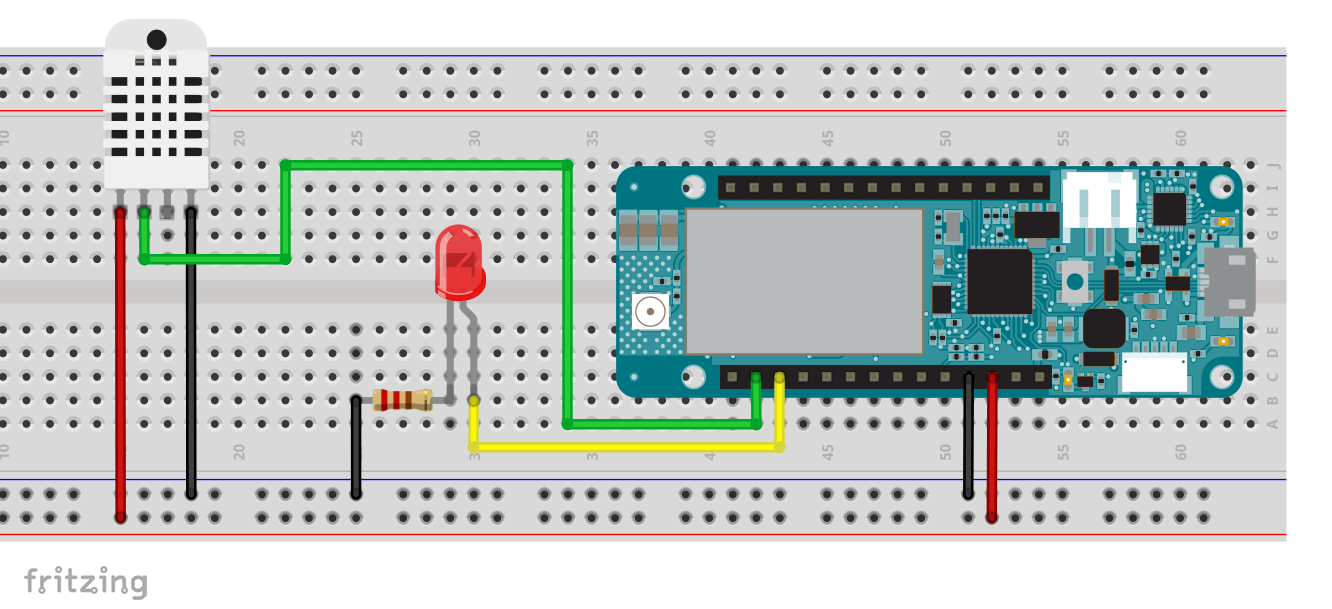
I took over the task for our thing from the last post. A DHT22 sensor shall be read and an LED shall be switched. Of course, you can also try anything else. Ideally, however, you should choose one property that you control (read and write) and another that you only read.
The test sketch
The sketch should look like this or similar.
#include "thingProperties.h"
#include "DHT.h"

#define LED_PIN 8
#define DHTPIN 7
#define DHTTYPE DHT22

DHT dht(DHTPIN, DHTTYPE);

void setup() {
  // You can of course delete all Serial Monitor Outputs after you've tested everything
  Serial.begin(9600);
  // This delay gives the chance to wait for a Serial Monitor without blocking if none is found
  delay(1500);
  dht.begin();
  pinMode(LED_PIN, OUTPUT);

  // Defined in thingProperties.h
  initProperties();

  // Connect to Arduino IoT Cloud
  ArduinoCloud.begin(ArduinoIoTPreferredConnection);

  setDebugMessageLevel(2);
  ArduinoCloud.printDebugInfo();
}

void loop() {
  static unsigned long lastMeasurement = millis();
  ArduinoCloud.update();
  if((millis() - lastMeasurement) > 3000){
    myTemp = dht.readTemperature();
    Serial.print("Temperatur: ");
    Serial.print(myTemp);
    Serial.println(" C");
    lastMeasurement = millis();
  }
}

void onLedStatusChange() {
    digitalWrite(LED_PIN, ledStatus);
    Serial.print("The light is ");
    if (ledStatus) {
        Serial.println("ON");
    } else {
        Serial.println("OFF");
    }
}
And here is the header file thingProperties.h:
#include <ArduinoIoTCloud.h>
#include <Arduino_ConnectionHandler.h>

const char THING_ID[]      = "e8095xxxxxxxxxxxxxxxxxxxxxxxxxbbc";

const char GPRS_APN[]      = SECRET_APN;
const char PINNUMBER[]     = SECRET_PIN;
const char GPRS_LOGIN[]    = SECRET_USERNAME;
const char GPRS_PASSWORD[] = SECRET_PASSWORD;

void onLedStatusChange();

CloudTemperature myTemp;
bool ledStatus;

void initProperties(){

  ArduinoCloud.setThingId(THING_ID);
  ArduinoCloud.addProperty(myTemp, READ, ON_CHANGE, NULL);
  ArduinoCloud.addProperty(ledStatus, READWRITE, ON_CHANGE, onLedStatusChange);

}

GSMConnectionHandler ArduinoIoTPreferredConnection(PINNUMBER, GPRS_APN, GPRS_LOGIN, GPRS_PASSWORD);
Finally, for the sake of completeness, the corresponding circuit:
Now we build our thing
To create a thing, follow the instructions on the Arduino pages. Click back to the Arduino Create page –> Arduino IoT Cloud –> ADD NEW THING. So everything like in the last post.
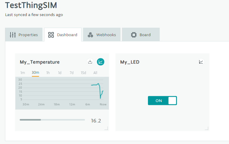
This time, however, I would like to show an option that I had mentioned only briefly so far. If you tick the box next to “Show History Visualization” in the Properties section, you can see the value history. I did this once and cooled down my sensor with cold spray. Here’s what the result looks like in the dashboard:
Data usage of the Arduino SIM card
The 5 MB/month provided to you with the Arduino SIM should actually be enough for a lot of data. To my astonishment, however, I found that the data usage of my sketch shown above was very high. The 5 MB would have been used up in a few days.
The call of ArduinoCloud.update() takes place at high frequency because I did not insert a delay into the main loop. Only every three seconds there is a break when the temperature is measured. However, in the property definition of temperature, I specified that an update should only be made if the delta is greater than or equal to 0.1 degrees to the last updated value. And since my workroom is quite constant tempered, the frequency of updates should be limited.
So the issue seems to be the size of the transmitted data packets. The measured value itself is only a “float” of four bytes. Surely the Thing ID will be sent along and some additional transmission protocol stuff. Encryption may also have an impact. A test with fixed update frequency (i.e. not “on change”) showed that per update of my temperature about 600 – 800 bytes are consumed. That means 5 MB for a month would allow updates about every 5 to 10 minutes.
I tried to understand what exactly is being transferred with the updates in the relevant libraries and header files. But then I “lost” myself in it and instead asked about the size of the data packets in the Arduino Forum (so far without an answer).
Solutions to reduce data consumption
One solution is to limit the number of ArduinoCloud.update() calls. In the example sketch above, you could, for example, add the function into the loop which ensures that the temperature is read only every 3 seconds. However, you would have to set the interval much higher. The disadvantage is that the LED is then switched accordingly delayed.
Or you don’t define an update “on change” but an update “every x seconds”.
Alternatively, you could only call the ArduinoCloud.update() function if you really need it, e.g. if limit values are exceeded, triggering an alarm system, etc. But then it becomes difficult to communicate into the direction of the board because without updating no switching….
In any case, at least initially, you should check the remaining data quota of the Arduino SIM card via Arduino Create –> Device Manager on a regular basis.
Sigfox
As already mentioned, Sigfox is first of all a French telecommunications company. Sigfox has built a wireless network which is based on the Low-Power Wide-Area Network (LPWAN) technology and uses 868 MHz. It is designed specifically for IoT applications that require low data transfer. If you want to know more about the company and the technology, then I recommend a look at this Wikipedia article and the Sigfox websites.
I have put relatively little effort into this part of the article. In essence, I just followed the instructions on the Arduino pages and modified them a bit:
Check the network coverage
Before you spend money on the hardware, you should check the availability of the Sigfox network for your project location. In August 2019, Sigfox (according to Sigfox) achieved an area coverage of 85% in Germany (link to article) and it is planned to increase that number.
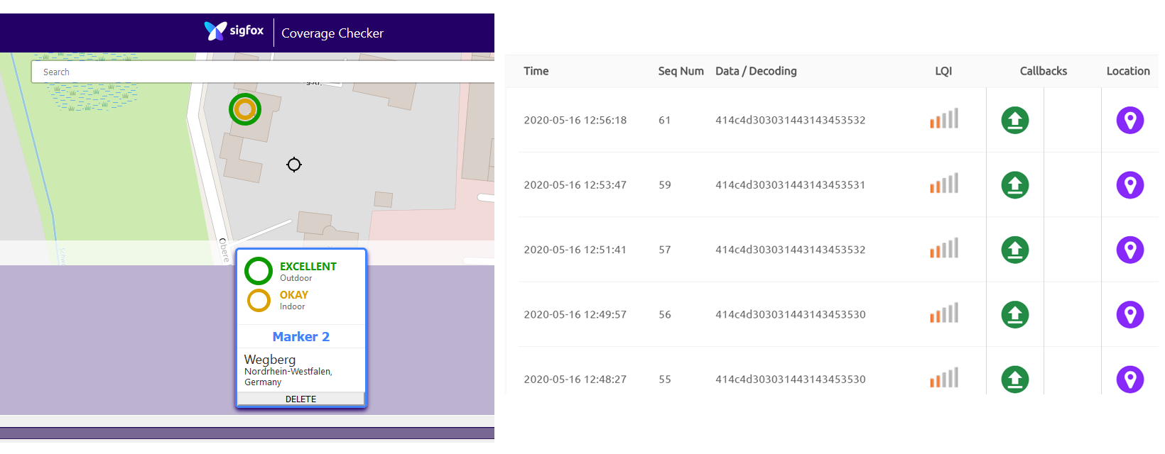
It’s best to check the availability for your location here. On the interactive map you will get information about the predicted indoor and outdoor connection quality. I zoomed into the map that I could check the network quality exactly for my house. The result was: outdoor – excellent and indoor – OK. The reality was: outdoor – borderline, indoor – didn’t work at all. I have to say, however, that the map predicted a bad connection a little further down the road. I recommend to set several markers on the map near your project location. If there are no bad results anywhere, I would be optimistic that it will actually work.
The Arduino MKR Fox 1200 Board
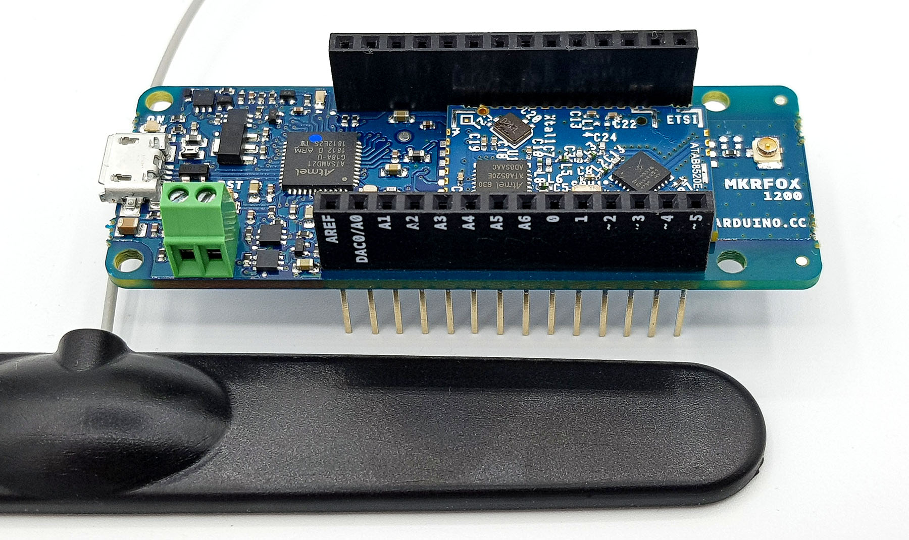
The MKR Fox 1200 is currently the only Arduino board designed for Sigfox.
This board is also based on the Low Power Arm® Cortex®-M0 32-bit SAMD21. Please pay attention to the board voltage of 3.3 volts again. You find additional technical data about the board here on the Arduino pages. In addition, I recommend a look at the Getting Started pages, as well as the functions of the Low Power Library.
The board costs 35 euros in the Arduino Store plus taxes and shipping (as of May 2020). This includes a one-year use of the Sigfox IoT service with 140 messages per day worth 20 euros. After that, you have to pay for the service. A price list for Germany can be found here. The price depends mainly on how many messages you want to send per day (2, 50 or 140).
Preparations
Preparing the Arduino IDE
First, you need to prepare the Arduino IDE. If you have not already done so, install the Arduino SAMD Boards in the Board Manager. Then you need the libraries “Arduino SigFox for MKRFox1200” and “Arduino Low Power”, which you get via the Library manager.
Sigfox Access
To get a Sigfox account, follow this link and select “Apply now”. First you will be asked for the company name, but you can alternatively type in your name. You will also be asked for your website – enter something there. This is followed by a number of other rather curious questions until you land here:
Before that, you received an email for setting your password. Now you can leave the Sigfox pages first.
Read Board ID and PAC
To read your Board ID and the so-called PAC, download the following sketch to the MKR Fox 1200:
#include <SigFox.h>
#include <ArduinoLowPower.h>

void setup() {
  Serial.begin(9600);

  while (!Serial) {};

  if (!SigFox.begin()) {
    Serial.println("Shield error or not present!");
    return;
  }
  String version = SigFox.SigVersion();
  String ID = SigFox.ID();
  String PAC = SigFox.PAC();

  // Display module informations
  Serial.println("MKRFox1200 Sigfox first configuration");
  Serial.println("SigFox FW version " + version);
  Serial.println("ID  = " + ID);
  Serial.println("PAC = " + PAC);

  Serial.println("");

//  Serial.print("Module temperature: ");
//  Serial.println(SigFox.temperatureL()); --> funktionierte nicht bei mir!

  Serial.println("Register your board on https://backend.sigfox.com/activate with provided ID and PAC");

  delay(100);

  // Send the module to the deepest sleep
  SigFox.end();

}

void loop() {
}
The output should look like this or similar:
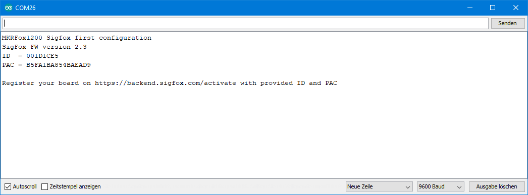
The ID is a unique identification number for your board, the PAC is a kind of security code for registering the board at Sigfox. Save the numbers or write them down.
Register MKR Fox 1200 with Sigfox
Now you navigate to the backend area of Sigfox and log in with the previously received credentials. Again, there are a number of questions. First, select the country:

Now you need the ID and the PAC. At “Tell us about your project” you can enter something (nicely something useful):

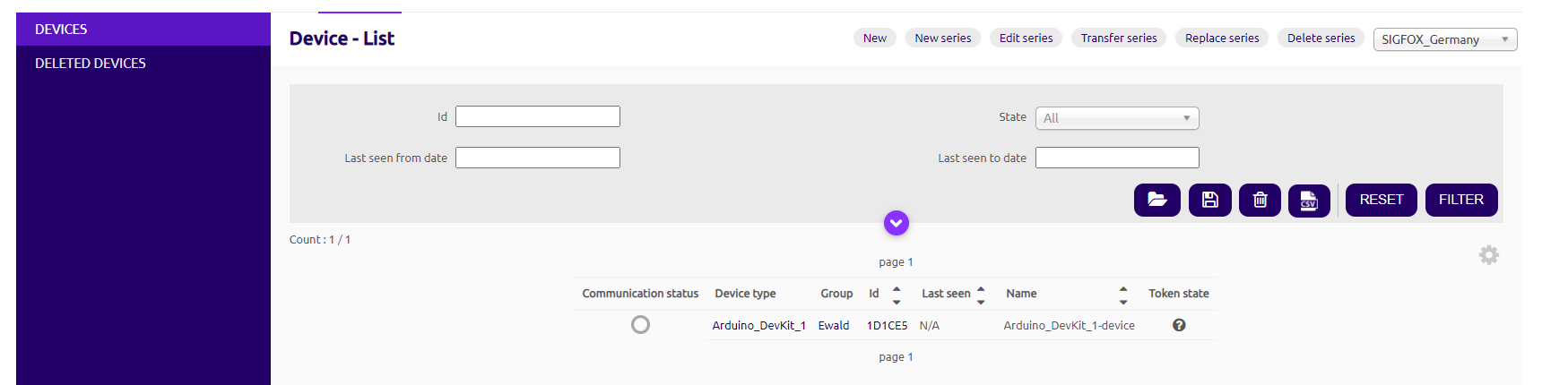
And more questions. With the company name, you take your name again, unless of course you have a company. Then select “Activate your Kit”. Now you find your board in the Device List:
Then go to the top of the menu to DEVICE TYPE, then click on the N/A under Keep alive, then select edit:

In the next window that opens, you enter a keep-alive value, e.g. 30 min and change the download mode to “DIRECT”. Then confirm with OK.

Click on Device at the top, then on your ID in the list. Here you can find information about your board. You can also click on the other menu items on the left (location, messages, etc.). But that’s not so much exciting, as you haven’t had any connections yet. Later you can come back here. Sigfox asks a lot, but also tells a lot.
A first test
Go back to the Arduino IDE and upload the following sketch to the MKR Fox 1200:
#include <SigFox.h>
#include <ArduinoLowPower.h>

void setup() {
  Serial.begin(9600);
  while (!Serial) {};

  // Uncomment this line and comment begin() if you are working with a custom board
  //if (!SigFox.begin(SPI1, 30, 31, 33, 28, LED_BUILTIN)) {
  if (!SigFox.begin()) {
    Serial.println("Shield error or not present!");
    return;
  }
  // Enable debug led and disable automatic deep sleep
  // Comment this line when shipping your project :)
  SigFox.debug();


  // Send the module to the deepest sleep
  SigFox.end();

  Serial.println("Type the message to be sent");
  while (!Serial.available());

  String message;
  while (Serial.available()) {
    message += (char)Serial.read();
  }

  // Every SigFox packet cannot exceed 12 bytes
  // If the string is longer, only the first 12 bytes will be sent

  if (message.length() > 12) {
    Serial.println("Message too long, only first 12 bytes will be sent");
  }

  Serial.println("Sending " + message);

  // Remove EOL
  message.trim();

  // Example of message that can be sent
  // sendString(message);

  Serial.println("Getting the response will take up to 50 seconds");
  Serial.println("The LED will blink while the operation is ongoing");

  // Example of send and read response
  sendStringAndGetResponse(message);
}

void loop()
{
}

void sendString(String str) {
  // Start the module
  SigFox.begin();
  // Wait at least 30mS after first configuration (100mS before)
  delay(100);
  // Clears all pending interrupts
  SigFox.status();
  delay(1);

  SigFox.beginPacket();
  SigFox.print(str);

  int ret = SigFox.endPacket();  // send buffer to SIGFOX network
  if (ret > 0) {
    Serial.println("No transmission");
  } else {
    Serial.println("Transmission ok");
  }

  Serial.println(SigFox.status(SIGFOX));
  Serial.println(SigFox.status(ATMEL));
  SigFox.end();
}

void sendStringAndGetResponse(String str) {
  // Start the module
  SigFox.begin();
  // Wait at least 30mS after first configuration (100mS before)
  delay(100);
  // Clears all pending interrupts
  SigFox.status();
  delay(1);

  SigFox.beginPacket();
  SigFox.print(str);

  int ret = SigFox.endPacket(true);  // send buffer to SIGFOX network and wait for a response
  if (ret > 0) {
    Serial.println("No transmission");
  } else {
    Serial.println("Transmission ok");
  }

  Serial.println(SigFox.status(SIGFOX));
  Serial.println(SigFox.status(ATMEL));

  if (SigFox.parsePacket()) {
    Serial.println("Response from server:");
    while (SigFox.available()) {
      Serial.print("0x");
      Serial.println(SigFox.read(), HEX);
    }
  } else {
    Serial.println("Could not get any response from the server");
    Serial.println("Check the SigFox coverage in your area");
    Serial.println("If you are indoor, check the 20dB coverage or move near a window");
  }
  Serial.println();

  SigFox.end();
}
In the serial monitor you enter any message of a maximum of 12 bytes. This is not a limitation of the sketch, but a limitation by Sigfox. More doesn’t fit in. If you want to send sensor data or similar later, you could choose e.g. 6 integers or 3 floats. What exactly you do in this test is not important, since you have not yet defined an action at Sigfox.
The moment of truth: now you see whether you can connect to Sigfox or not. If all goes well, you should get an answer from Sigfox:
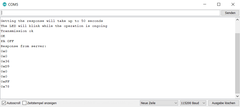
If the connection doesn’t work, you could place the antenna near a window or try it outside again.
When you return to Sigfox and to your device, you’ll find information about connection quality, the number of messages sent, and more.
An Event Trigger
Now we want Sigfox to work for us. That means, when Sigfox receives a message, a specific action should follow. As a simple example, taken from here, two buttons are attached to the MKR Fox 1200. If one of the buttons is pressed, a message is sent to Sigfox and Sigfox should inform you by e-mail.
Preparations on the Sigfox web page
Go back to Sigfox in the backend area. Go to Device at the top of the page, and then to the entry under Device-Type in the Device-List:

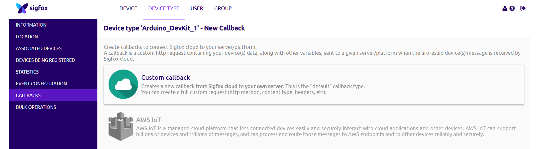
Then click on callbacks on the left side menu. Next, click on “New” (top right). Then select “Custom callbacks” from the list:
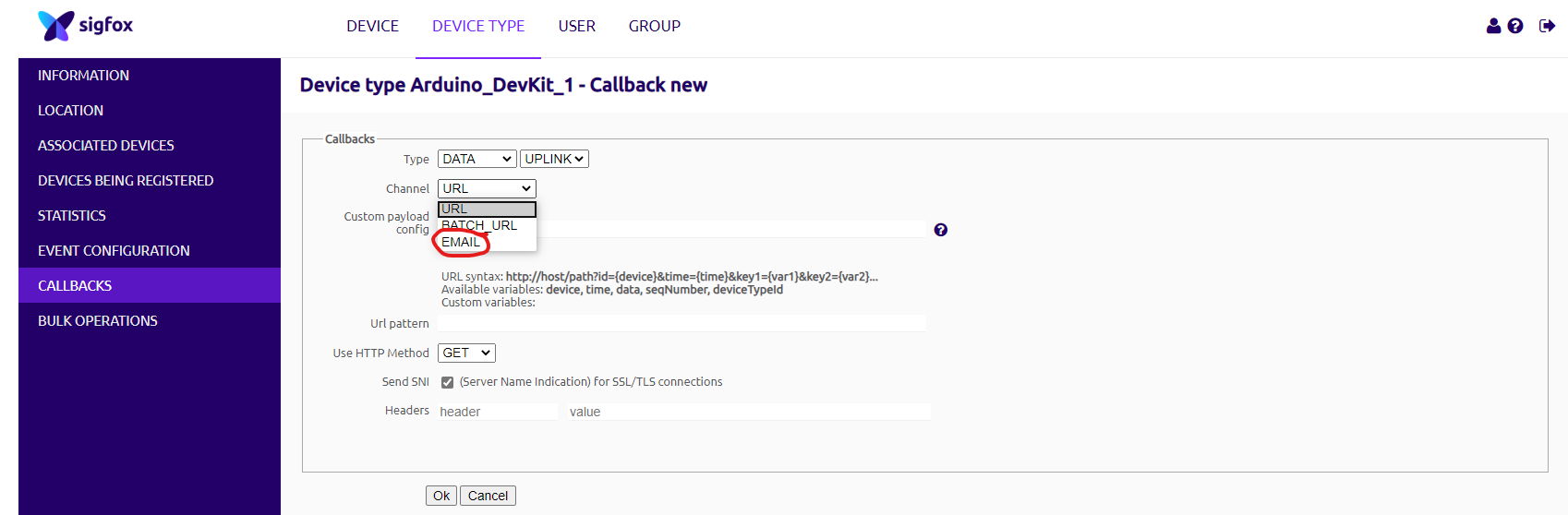
In the next window, you select EMAIL as CHANNEL:
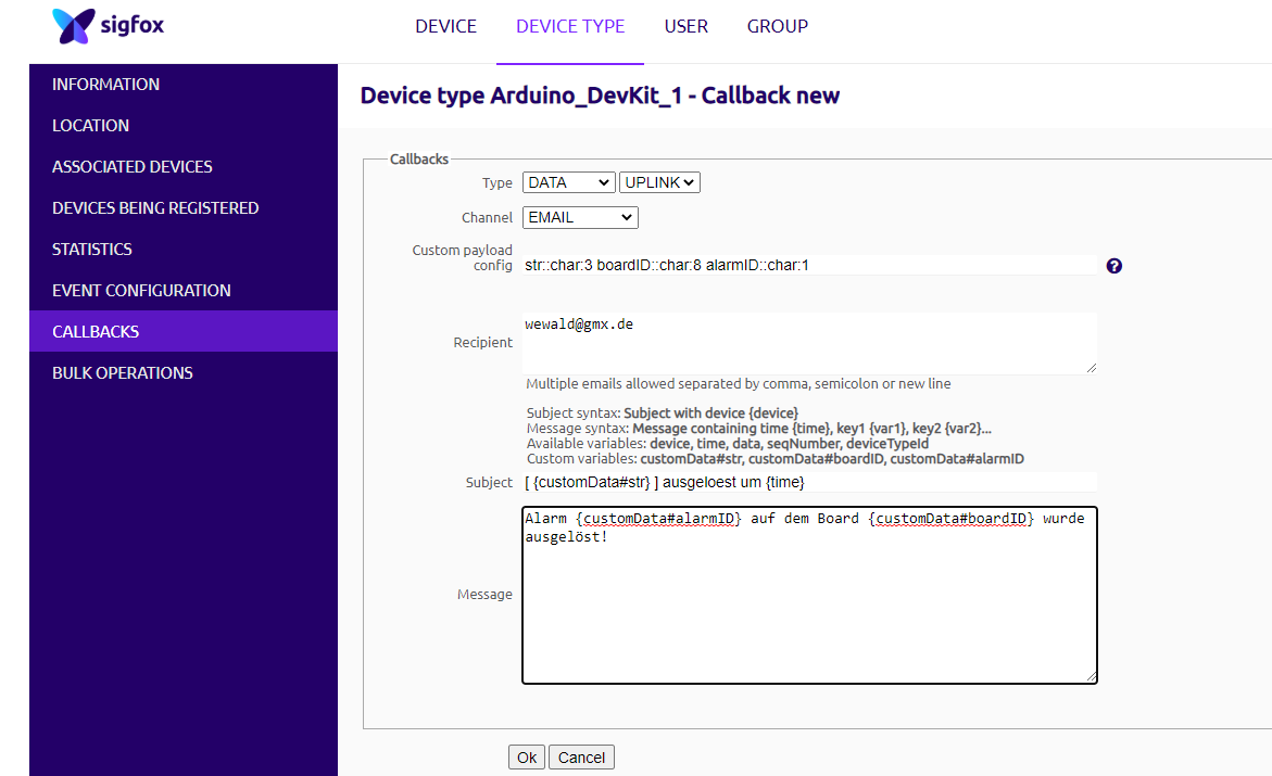
Then comes the most important point. You enter the structure of your messages in the “Custom payload config” field, in this example:
- str::char:3 boardID::char:8 alarmID::char:1
This means that the 12 byte message shall be interpreted as follows:
- the variable “str” are the first three characters
- followed by “boardID” with eight characters
- and finally the “alarmID” which is a single char
How you divide this up and how you name the variables is completely up to you. You only have to ensure that you end up with twelve bytes.
As recipient, enter the destination email address.
In the subject and message you can then write free text and use the variables. For the variables, you use the following spelling:
- {customData#Name_der_Variablen}
In addition to the variable type char, you can also pass integer types, floats, bools, etc. If you click on the question mark behind “Custom payload config”, you will get a guide to encoding the variables.
Preparations on the Arduino side
Upload the following sketch on your MKR Fox 1200 board:
/*
SigFox Event Trigger tutorial
This sketch demonstrates the usage of a MKRFox1200
to build a battery-powered alarm sensor with email notifications
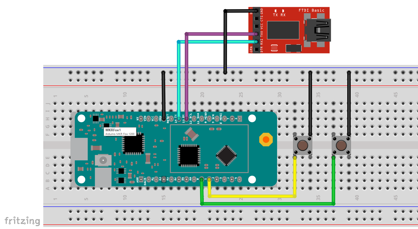
A couple of sensors (normally open) should we wired between pins 1 and 2 and GND.
This example code is in the public domain.
*/
#include <SigFox.h>
#include <ArduinoLowPower.h>
// Set debug to false to enable continuous mode
// and disable serial prints
int debug = true;
volatile int alarm_source = 0;
void setup() {
if (debug == true) {
// We are using Serial1 instead than Serial because we are going in standby+
// and the USB port could get confused during wakeup. To read the debug prints,
// connect pins 13-14 (TX-RX) to a 3.3V USB-to-serial converter
Serial1.begin(115200);
while (!Serial1) {}
}
if (!SigFox.begin()) {
//something is really wrong, try rebooting
reboot();
}
//Send module to standby until we need to send a message
SigFox.end();
if (debug == true) {
// Enable debug prints and LED indication if we are testing
SigFox.debug();
}
// attach pin 0 and 1 to a switch and enable the interrupt on voltage falling event
pinMode(0, INPUT_PULLUP);
LowPower.attachInterruptWakeup(0, alarmEvent1, FALLING);
pinMode(1, INPUT_PULLUP);
LowPower.attachInterruptWakeup(1, alarmEvent2, FALLING);
}
void loop()
{
// Sleep until an event is recognized
LowPower.sleep();
// if we get here it means that an event was received
SigFox.begin();
if (debug == true) {
Serial1.println("Alarm event on sensor " + String(alarm_source));
}
delay(100);
// 3 bytes (ALM) + 4 bytes (ID) + 1 byte (source) < 12 bytes
String to_be_sent = "ALM" + SigFox.ID() + String(alarm_source);
SigFox.beginPacket();
SigFox.print(to_be_sent);
int ret = SigFox.endPacket();
// shut down module, back to standby
SigFox.end();
if (debug == true) {
if (ret > 0) {
Serial1.println("No transmission");
} else {
Serial1.println("Transmission ok");
}
Serial1.println(SigFox.status(SIGFOX));
Serial1.println(SigFox.status(ATMEL));
// Loop forever if we are testing for a single event
while (1) {};
}
}
void alarmEvent1() {
alarm_source = 1;
}
void alarmEvent2() {
alarm_source = 2;
}
void reboot() {
NVIC_SystemReset();
while (1);
}
The sketch (which I copied from the Arduino web pages) is easy to understand, but has a few particularities:
- The Sketch uses the Low Power Library to save power on battery-powered projects, so it uses
LowPower.attachInterruptWakeUp()instead of the traditionalattachInterrupt(). The function ensures that the board wakes up from Sleep Mode when the button is pressed and the interrupt is triggered. - The sleep function or the wake-up could make problems with the USB port. Therefore, the output is assigned to Serial1, which is on pin 13 and 14.
- To get the output to the serial monitor, you need to use a USB-to-serial adapter. You can get it for a few euros e.g. here.
- Once you have uploaded the sketch, you will no longer see the port for your board in the Arduino IDE. You switch to the port of the USB-to-Serial Adapter. Then you can track the debug outputs on the serial monitor.
- Sporadically, the “Board Port” did not appear at all. In this case, double-clicking on the reset button of the board may solve the issue. If necessary, you can also upload the sketches via the USB-to-Serial Adapter. Also in this case, you can double-click the reset button beforehand.
The result
If you press one of the two buttons now, you will get an output on the serial monitor like the one shown below. The error messages do not necessarily mean that the message has not been received:
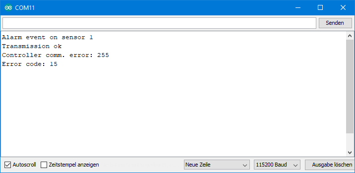
It is much more important whether you have now received an email like the following:
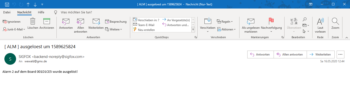
The time (“ausgelöst um” = triggered by …) is in seconds. The zero point, by the way, refers to the beginning of the Unix era on 1 January 1970. More information on this topic can be found here. Might be interesting.
More on Sigfox
I have only scratched the surface of the Sigfox universe with this post. For example, instead of sending e-mails, you could also send the event messages to a website to update the status there. On the one hand, however, dealing with this would go beyond the scope of this article, and on the other hand, this kind of things is not exactly my core competency.
Arduino IoT, Arduino SIM and Sigfox – my preliminary conclusion
Here is my conclusion, which relates to this and my last article.
Arduino IoT in general (via Wi-Fi or cable)
Positives:
- Easy to set up
- Visually appealing (New Dashboards)
- Advanced features using webhooks (not yet discussed)
- Security is guaranteed by the crypto chips on the boards
Negatives:
- Restrictions on free operation (Free Plan)
- Works only with Arduino boards – and these are quite expensive
- Limited degrees of freedom, prefabricated system
Arduino SIM
Positives:
- Easy to set up
- Wi-Fi independent, good coverage
- Contract can be cancelled or paused at any time
Negatives:
- Works only with the MKR GSM 1400
- High acquisition costs
- 5 MB are exhausted faster than expected
- Little transparency regarding the size of the data packets
Sigfox
Here, of course, I have to say that I can only speak about access via Arduino and not about Sigfox in general.
Positives:
- Relatively easy to set up
- Very transparent (statistics, data consumption, etc.)
- Free for one year with the purchase of an MKR Fox 1200
Neutrals:
- Limited to 140 messages, which is about 1 message per 10 minutes
- Whether this is sufficient or not depends on the project
- In the end similar to the Arduino SIM, but at least you can plan exactly with it – with the Arduino SIM this is more difficult
Negatives:
- Works only with the MKR Fox 1200 (again: only relating to access via Arduino!)
- Network coverage not as reliable as the interactive map suggests
- No visualization of transferred data (analogous to the Arduino IoT Dashboard) – you would have to design this completely yourself
Outlook
What has bothered me – and perhaps some of you too – in this and the last post is the dependence on special boards, the investment costs and running costs. It’s all pretty simple, but it’s also a pretty tight corset that you put on.
In the next article I would like to stay on the subject of Internet of Things. In particular, it will be about the topic of webhooks and how you can use them with the free IFTTT (if this then that) service. I will use the ESP8266 ESP-01 board for this, which is a cost-effective and widely used board.
In an even later article (perhaps the next one) I will discuss GSM modules, which can be an alternative to the Arduino SIM and Sigfox.