
About the post
In my series about light, gesture, motion and distance sensors, which I will conclude with an overall overview, I would like to introduce the distance sensors VL53L0X and VL53L1X this time. Technically, these can be regarded as big brothers of the VL6180X, which I introduced in my last post. I will first discuss the properties of the actual sensors and modules. Then I will introduce libraries that make it easy to use the functions of the VL53L0X and VL53L1X.
The most significant difference between the three sensors is their range. You can use the VL6180X up to distances of 20 cm. The VL53L0X and VL53L1X have much longer ranges of up to 200 and 400 cm respectively. Data sheets for the VL53L0X and VL53L1X can be found here or here.
The measuring principle
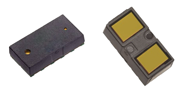
The sensors work according to the time-of-flight (ToF) principle. They have an IR laser whose reflected rays are evaluated in terms of their flight time. The IR laser is a Vertical Cavity Surface-Emitting Laser (VCSEL) with a wavelength of 940 nanometers invisible to humans. The reflected light is detected by a photodiode array. The sensors use so-called Single Photon Avalanche Diodes (SPADs).
VL53L0X and VL53L1X achieve a resolution in millimeters. To cover one millimeter, light takes about 3.3 x 10⁻¹² seconds. So, it’s amazing that a cheap mass-produced article can offer such a high resolution. If a computer or microcontroller only performed a single clock during this time, this would be equivalent to a clock speed of 330 GHz. And with a single clock, you still haven’t performed any calculation operation.
For those who have not read the last article: if you are interested in the details of the method, you can read an article about it here or get smart here on Wikipedia.
Basic properties
VL53L0X vs VL53L1X – Similarities
General comments
Vl53L0X and VL53L1X are pure distance sensors, unlike the VL6180X. Both tolerate a voltage range between 2.6 and 3.5 volts. However, this only applies to the bare sensors. For the modules, on the other hand, the voltage range depends on the individual design. Both sensors have identical pinouts.
Calibration
Both sensors can be calibrated regarding various parameters, which are particularly useful when the devices are installed in housings. For example, you can set a distance offset.
If you install the VL53L0X or VL53L1X behind a cover glass, the reflection results in the so-called cross-talk effect, which leads to errors in the distance measurement. This effect can be minimized by calibration. For further calibrations, please look at the data sheets.
Communication and control via APIs
Communication is via I2C. You can change the default I2C address (0x29) via commands and not via address pins as you might be used to. However, both sensors “forget” the new address when disconnected from power. By cleverly using the XSHUT pins (to be discussed) you can create a procedure that performs the address change again each time it is switched on.
The control of VL53L0X and VL53L1X is somewhat unusual. Because normally, you are used to being provided with data sheets including register lists. Here, on the other hand, the manufacturer STMicroelectronics has decided to provide so-called APIs (Application Programming Interfaces). I am not the first to be surprised about this, nor the only one who would have liked to have had a normal register documentation. There is also a discussion in the STM community, including a statement from the manufacturer.
The description of the VL53L0X API can be found here, for the VL53L1X see here.
Interrupts
Both sensors have interrupt functions. You can be informed by an interrupt if a new reading is available. Or you can set a threshold above or below which an interrupt is triggered. Alternatively, you can define a window inside or outside where an interrupt is triggered.
VL53L0X vs. VL53L1X – Differences
Range
As already mentioned, the most obvious difference between the VL53L0X and VL53L1X is the range. Under optimal conditions, i.e. with good reflection of the surface to be detected and little interference light, you can reach up to two meters with the VL53L0X, but with the VL53L1X up to four meters.
Measuring profiles
On the VL53L0X you can change various parameters to optimize performance for different application conditions. This includes above all the maximum measuring time (timing budget), but also the permissible dispersion of the results, the laser pulse periods and the minimum signal rate. The statistical variance is given as sigma in mm because interference signals are detected time-shifted to the reference value and this deviation over the speed of light corresponds to a distance.
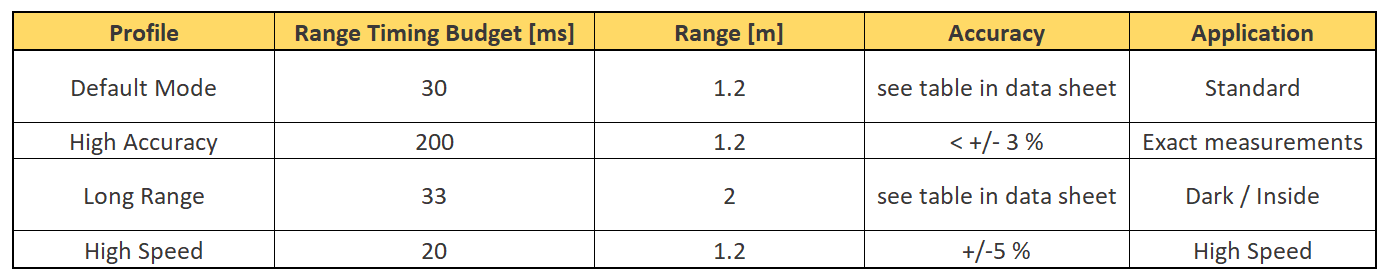
You are relatively free to choose the parameters, but you have to be careful that the settings do harmonize. Because in the worst case, you always exceed the timing budget without a valid metric. It is convenient that there are pre-built profiles in the description of the API for the VL53L0X:
The VL53L1X offers the three distance modes Long, Medium and Short. For these modes, the measurement parameters are predefined or linked in the API. However, you can change some parameters to generate measurements under unfavorable conditions, for example. How accurate these measurement results are then is another question.
The range depends on the ambient light to varying degrees, depending on the mode. Here are the values in the dark / in strong ambient light at 88% reflection and timing budget of 100 milliseconds:
- Short: 136 cm / 135 cm
- Medium: 290 cm / 76 cm
- Long: 360 cm / 73 cm
Selecting “long” on the VL53L1X is no guarantee that you will reach really long ranges under all conditions! With lots of light, you can reach even longer ranges using “short”.
In addition to the choice of distance mode, the range and accuracy of the VL53L1X is also affected by the timing budget. 20 milliseconds is the shortest setting that only works in short mode. At 140 milliseconds, the 4 meters can be reached in the dark provided good reflection. In the data sheet there are graphs showing the dependence on distance and repeatability vs. timing budget.
Measuring frequency
With the VL53L0X you can set the following modes regarding the measuring frequency:
- Single ranging: single measurement “on request” (polling)
- Continuous ranging: if one measurement is finished, the next one is immediately started
- Timed ranging: continuous measurement with adjustable pauses in between
The VL53L1X only offers continuous mode and timed ranging Mode.
(De-)activation of spads
The VL53L1X has a 16 x 16 spad array for detection. By default, all spads are enabled. This creates a conical field of view (FoV) covering 27°. By disabling a part of the pads, the cone can be narrowed to 15° at 4 x 4 activated spads and the direction (ROI = Region Of Interest) can be specified. The VL53L0X does not offer these options.
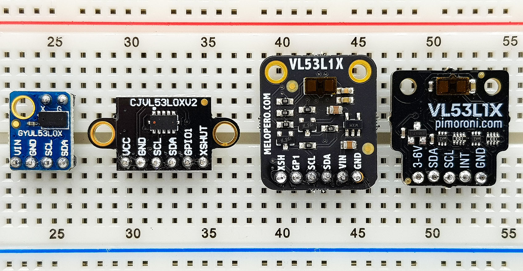
VL53L0X and VL53L1X modules
Prices
Vl53L0X modules are available on Amazon, for example, in a wide price range from approx. 7 euros (including shipping) to over 20 euros. I didn’t see VL53L1X modules under 16 euros on Amazon (as of August 2019). This is certainly because the sensor has only been available since the beginning of 2018. The price will certainly go down.
Properties
In contrast to the bare sensors, the modules usually have voltage regulators, so you can usually operate them between 2.8 and 5.5 volts. Checks the supplier’s details.
Most modules have six inputs/outputs. In addition to GND / VCC and SDA/SCL for I2C communication, these are XSHUT and GPIO1. Sometimes the labeling is slightly different. XSHUT is used to turn off the module. To do this, you have to set XSHUT to LOW. A module-internal pull-up resistor sets the pin to HIGH, i.e. you can just leave it unconnected if you don’t want to use the feature. GPIO1 is the interrupt output. If you don’t use interrupts, you can leave it unconnected. The interrupt polarity can be adjusted.
Wiring

The wiring of the VL53L0X and VL53L1X modules is identical. I didn’t need pull-up resistors for the I2C lines. You have to try it yourself. Pin 3 serves as an interrupt pin. The LED on pin 13 is required for one of the sample sketches.
Libraries
I tried some libraries for the sensors. Unfortunately, I couldn’t find a library for the VL53L0X that I was fully satisfied with. In particular, the interrupt functions were not implemented. However, the distance measurement itself works, for example, with the library of Adafruit or with that of Pololu. The Adafruit library provides an example sketch for operating two VL53L0X. The procedure is also described here in the learning area of Adafruit. Overall, however, I liked the library of Pololu better.
For the VL53L1X, the Sparkfun library is my favorite because it has implemented all the features that I consider to be relevant. You can get it here on Github or you can search for it through the library manager of the Arduino IDE.
Control of the VL53L0X with the Pololu library
The example sketch for single measurements supplied by Pololu has implemented the above-mentioned measurement profiles from the user manual of the VL53L0X API. The default is the default mode. If you want to enable the long range, high-speed or high accuracy mode, all you have to do is uncommenting the corresponding “#define” lines. You can also change the conditions for these modes. However – as already mentioned before – of course, all this has to fit together.
/* This example shows how to get single-shot range
 measurements from the VL53L0X. The sensor can optionally be
 configured with different ranging profiles, as described in
 the VL53L0X API user manual, to get better performance for
 a certain application. This code is based on the four
 "SingleRanging" examples in the VL53L0X API.

 The range readings are in units of mm. */

#include <Wire.h>
#include <VL53L0X.h>

VL53L0X sensor;

// Uncomment this line to use long range mode. This
// increases the sensitivity of the sensor and extends its
// potential range, but increases the likelihood of getting
// an inaccurate reading because of reflections from objects
// other than the intended target. It works best in dark
// conditions.

//#define LONG_RANGE

// Uncomment ONE of these two lines to get
// - higher speed at the cost of lower accuracy OR
// - higher accuracy at the cost of lower speed

//#define HIGH_SPEED
//#define HIGH_ACCURACY

void setup()
{
  Serial.begin(9600);
  Wire.begin();

  sensor.init();
  sensor.setTimeout(500);

#if defined LONG_RANGE
  // lower the return signal rate limit (default is 0.25 MCPS)
  sensor.setSignalRateLimit(0.1);
  // increase laser pulse periods (defaults are 14 and 10 PCLKs)
  sensor.setVcselPulsePeriod(VL53L0X::VcselPeriodPreRange, 18);
  sensor.setVcselPulsePeriod(VL53L0X::VcselPeriodFinalRange, 14);
#endif

#if defined HIGH_SPEED
  // reduce timing budget to 20 ms (default is about 33 ms)
  sensor.setMeasurementTimingBudget(20000);
#elif defined HIGH_ACCURACY
  // increase timing budget to 200 ms
  sensor.setMeasurementTimingBudget(200000);
#endif
}

void loop()
{
  Serial.print(sensor.readRangeSingleMillimeters());
  if (sensor.timeoutOccurred()) { Serial.print(" TIMEOUT"); }

  Serial.println();
}
An example sketch for the continuous mode is also part of the library. But it only really makes sense in conjunction with interrupts. And they don’t seem to be implemented in the library (so far).
/* This example shows how to use continuous mode to take
range measurements with the VL53L0X. It is based on
vl53l0x_ContinuousRanging_Example.c from the VL53L0X API.

The range readings are in units of mm. */

#include <Wire.h>
#include <VL53L0X.h>

VL53L0X sensor;

void setup()
{
  Serial.begin(9600);
  Wire.begin();

  sensor.init();
  sensor.setTimeout(500);

  // Start continuous back-to-back mode (take readings as
  // fast as possible).  To use continuous timed mode
  // instead, provide a desired inter-measurement period in
  // ms (e.g. sensor.startContinuous(100)).
  sensor.startContinuous();
}

void loop()
{
  Serial.print(sensor.readRangeContinuousMillimeters());
  if (sensor.timeoutOccurred()) { Serial.print(" TIMEOUT"); }

  Serial.println();
}
Control of the VL53L1X with the Sparkfun library
As a start for the Sparkfun library, I recommend the example sketch “Example2_SetDistanceMode.ino”. The library has implemented the distance modes “Short” (up to 1.3 meters) and “Long” (up to 4 meters). Otherwise, no further adjustment options are shown in the sketch.
/*
  Reading distance from the laser based VL53L1X
  By: Nathan Seidle
  Revised by: Andy England
  SparkFun Electronics
  Date: April 4th, 2018
  License: This code is public domain but you buy me a beer if you use this and we meet someday (Beerware license).

  SparkFun labored with love to create this code. Feel like supporting open source hardware?
  Buy a board from SparkFun! https://www.sparkfun.com/products/14667

  This example prints the distance to an object.

  Are you getting weird readings? Be sure the vacuum tape has been removed from the sensor.
*/

#include <Wire.h>
#include "SparkFun_VL53L1X.h"

//Optional interrupt and shutdown pins.
#define SHUTDOWN_PIN 2
#define INTERRUPT_PIN 3

SFEVL53L1X distanceSensor;
//Uncomment the following line to use the optional shutdown and interrupt pins.
//SFEVL53L1X distanceSensor(Wire, SHUTDOWN_PIN, INTERRUPT_PIN);

void setup(void)
{
  Wire.begin();

  Serial.begin(9600);
  Serial.println("VL53L1X Qwiic Test");

  if (distanceSensor.begin() == true)
  {
    Serial.println("Sensor online!");
  }

  distanceSensor.setDistanceModeShort();
  //distanceSensor.setDistanceModeLong();
}

void loop(void)
{
  distanceSensor.startRanging(); //Write configuration bytes to initiate measurement

  int distance = distanceSensor.getDistance(); //Get the result of the measurement from the sensor

  distanceSensor.stopRanging();

  Serial.print("Distance(mm): ");
  Serial.print(distance);

  float distanceInches = distance * 0.0393701;
  float distanceFeet = distanceInches / 12.0;

  Serial.print("\tDistance(ft): ");
  Serial.print(distanceFeet, 2);

  Serial.println();
}
If you look at the public functions of the library file, you will get a good overview of the settings implemented in the library Sparkfun_VL53L1X. These are very well commented:
bool init(); //Deprecated version of begin
  bool begin(); //Initialization of sensor
  bool checkID(); //Check the ID of the sensor, returns true if ID is correct
  void sensorOn(); //Toggles shutdown pin to turn sensor on and off
    void sensorOff(); //Toggles shutdown pin to turn sensor on and off
  VL53L1X_Version_t getSoftwareVersion(); //Get's the current ST software version
  void setI2CAddress(uint8_t addr); //Set the I2C address
  int getI2CAddress(); //Get the I2C address
  void clearInterrupt(); // Clear the interrupt flag
  void setInterruptPolarityHigh(); //Set the polarity of an active interrupt to High
  void setInterruptPolarityLow(); //Set the polarity of an active interrupt to Low
  uint8_t getInterruptPolarity(); //get the current interrupt polarity
  void startRanging(); //Begins taking measurements
  void stopRanging(); //Stops taking measurements
  bool checkForDataReady(); //Checks the to see if data is ready
  void setTimingBudgetInMs(uint16_t timingBudget); //Set the timing budget for a measurement
  uint16_t getTimingBudgetInMs(); //Get the timing budget for a measurement
  void setDistanceModeLong(); //Set to 4M range
  void setDistanceModeShort(); //Set to 1.3M range
  uint8_t getDistanceMode(); //Get the distance mode, returns 1 for short and 2 for long
  void setIntermeasurementPeriod(uint16_t intermeasurement); //Set time between measurements in ms
  uint16_t getIntermeasurementPeriod(); //Get time between measurements in ms
  bool checkBootState(); //Check if the VL53L1X has been initialized
  uint16_t getSensorID(); //Get the sensor ID
  uint16_t getDistance(); //Returns distance
  uint16_t getSignalPerSpad(); //Returns the average signal rate per SPAD (The sensitive pads that detect light, the VL53L1X has a 16x16 array of these) in kcps/SPAD, or kilo counts per second per SPAD.
  uint16_t getAmbientPerSpad(); //Returns the ambient noise when not measuring a signal in kcps/SPAD.
  uint16_t getSignalRate(); //Returns the signal rate in kcps. All SPADs combined.
  uint16_t getSpadNb(); //Returns the current number of enabled SPADs
  uint16_t getAmbientRate(); // Returns the total ambinet rate in kcps. All SPADs combined.
  uint8_t getRangeStatus(); //Returns the range status, which can be any of the following. 0 = no error, 1 = signal fail, 2 = sigma fail, 7 = wrapped target fail
  void setOffset(int16_t offset); //Manually set an offset in mm
  int16_t getOffset(); //Get the current offset in mm
  void setXTalk(uint16_t xTalk); //Manually set the value of crosstalk in counts per second (cps), which is interference from any sort of window in front of your sensor.
  uint16_t getXTalk(); //Returns the current crosstalk value in cps.
  void setDistanceThreshold(uint16_t lowThresh, uint16_t hiThresh, uint8_t window);//Set bounds for the interrupt. lowThresh and hiThresh are the bounds of your interrupt while window decides when the interrupt should fire. The options for window are shown below.
  //0: Interrupt triggered on measured distance below lowThresh.
  //1: Interrupt triggered on measured distance above hiThresh.
  //2: Interrupt triggered on measured distance outside of bounds.
  //3: Interrupt triggered on measured distance inside of bounds.
  uint16_t getDistanceThresholdWindow(); //Returns distance threshold window option
  uint16_t getDistanceThresholdLow(); //Returns lower bound in mm.
  uint16_t getDistanceThresholdHigh(); //Returns upper bound in mm
  void setROI(uint16_t x, uint16_t y); //Set the height and width of the ROI in SPADs, lowest possible option is 4. ROI is always centered.
  uint16_t getROIX(); //Returns the width of the ROI in SPADs
  uint16_t getROIY(); //Returns the height of the ROI in SPADs
  void setSignalThreshold(uint16_t signalThreshold); //Programs the necessary threshold to trigger a measurement. Default is 1024 kcps.
  uint16_t getSignalThreshold(); //Returns the signal threshold in kcps
  void setSigmaThreshold(uint16_t sigmaThreshold); //Programs a new sigma threshold in mm. (default=15 mm)
  uint16_t getSigmaThreshold(); //Returns the current sigma threshold.
  void startTemperatureUpdate(); //Recalibrates the sensor for temperature changes. Run this any time the temperature has changed by more than 8°C
  void calibrateOffset(uint16_t targetDistanceInMm); //Autocalibrate the offset by placing a target a known distance away from the sensor and passing this known distance into the function.
  void calibrateXTalk(uint16_t targetDis
I wrote my own sketch in which I defined an interrupt window. When a distance is detected within the thresholds, an interrupt is triggered, the LED on pin 13 lights up and a message is displayed on the serial monitor. In addition, I have added a function to the sketch, which outputs some settings of the VL53L1X on the serial monitor at the beginning.
#include <ComponentObject.h>
#include <RangeSensor.h>
#include <SparkFun_VL53L1X.h>
#include <vl53l1x_class.h>
#include <vl53l1_error_codes.h>


#include <Wire.h>
#include "SparkFun_VL53L1X.h"

//Optional interrupt and shutdown pins.
#define SHUTDOWN_PIN 2
#define INTERRUPT_PIN 3
volatile bool event = false;
byte ledPin = 13;

//SFEVL53L1X distanceSensor;
//Uncomment the following line to use the optional shutdown and interrupt pins.
SFEVL53L1X distanceSensor(Wire, SHUTDOWN_PIN, INTERRUPT_PIN);

void setup() {
  Wire.begin();
  distanceSensor.sensorOn();
  attachInterrupt(digitalPinToInterrupt(INTERRUPT_PIN), blink, FALLING);
  pinMode(ledPin, OUTPUT);
  Serial.begin(9600);
  Serial.println("Interrupt Test");

  if (distanceSensor.begin() == true) {
    Serial.println("Sensor online!");
  }

  distanceSensor.setInterruptPolarityLow();
  distanceSensor.setDistanceThreshold(300, 1000, 3);
  showSettings();
  delay(2000); // um Zeit zu haben die Settings zu sehen
  distanceSensor.startRanging();
  event = false;
  distanceSensor.clearInterrupt();

}

void loop(void) {
  if (event) {
    int distance = distanceSensor.getDistance();
    Serial.print("Interrupt! Current distance: ");
    Serial.println(distance);
    digitalWrite(ledPin, HIGH);
    delay(500);
    digitalWrite(ledPin, LOW);
    event = false;
    distanceSensor.clearInterrupt();
  }
}

void blink() {
  event = true;
}

void showSettings() {
  Serial.print("Interrupt polarity is: ");
  byte interruptPolarity = distanceSensor.getInterruptPolarity();
  if (interruptPolarity == 0) {
    Serial.println("Low");
  }
  if (interruptPolarity == 1) {
    Serial.println("High");
  }
  Serial.print("Offset [mm]: ");
  unsigned int offset = distanceSensor.getOffset();
  Serial.println(offset);
  Serial.print("Distance Mode: ");
  byte distMode = distanceSensor.getDistanceMode();
  if (distMode == 1) {
    Serial.println("Short Mode");
  }
  else if (distMode == 2) {
    Serial.println("Long Mode");
  }
  unsigned int timingBudget = distanceSensor.getTimingBudgetInMs();
  Serial.print("Timing Budget: ");
  Serial.println(timingBudget);

  unsigned int interMeasurementPeriod = distanceSensor.getIntermeasurementPeriod();
  Serial.print("Inter Measurement Period [ms]: ");
  Serial.println(interMeasurementPeriod);

  unsigned int spads = distanceSensor.getROIX();
  Serial.print("Active Spad Array, x: ");
  Serial.print(spads);
  spads = distanceSensor.getROIY();
  Serial.print(", y: ");
  Serial.println(spads);
}
Encountered problems
Most features work wonderfully, but I’ve noticed a few minor issues:
- If you change the I2C address with
setI2CAddress(), then it becomes an address moved by one bit. Internally, the read/write bit appears to be added. - I could only reduce the Spad Array to a minimum of 11 x 11. There were no more reasonable results below that – no matter what else I set
- From time to time, the VL53L1X does not do what it is supposed to do after changing settings. Then it helps to take him off power for a short time. By the way, this also applies to the VL53L0X.
Acknowledgement
The little male on the post picture is from Peggy and Marco Lachmann-Anke on Pixabay. Holger Langmaier made the tape measure, also on Pixabay. The Fritzing scheme of the VL53L0X comes from Adafruit on Github. Then, of course, I would like to thank Pololu and Sparkfun for the libraries.
Thank you for this tutorial very helpfull, but I wanted to ask about the RIO, I need to do some kind of hand gestures with this sensor, due to time limit unfortunatly I cant change the sensor and use the vl53l1 which unables multi yone detection, so Im thinking of using multiple ROIs to do unable multi detection, do zou think its possible and I will apreciate it if you have any advice regarding where can I find more infos about this :)?
Best Regards
Samer
I don’t know how to reliably detect gestures like up/down or left/right with the V53L1X. What’s of course possible is to detect a gesture which changes the distance. The only idea which comes in my mind is to use the minimum number of spads to narrow the detection angle. If you then wave with your hand while you are near to the sensor you might detect your hand when it’s in front of the sensor and don’t detect it, when it’s moved up/down/left/right. I.e. you would see a short distance signal which disappears and appears repeatedly. It should be possible to analyse this data.
Despite following your excellent tutorial, two of my VL53L0Xs refused to work on a Nano Every or even a UNO with either the Pololu or Adafruit libraries.
Despite all my experience getting other Arduino bits and pieces to work together including nRFL01s and a MH-Z19C (with your help), I couldn’t get this simple device to work.
Until I found a stackexchange entry that said at least some VL53L0Xs refuse to work until XSHUT is pulled up to 3.3 Volts. And others need to have their contacts well cleaned after soldering them.
I hope this is of some use to you and your many followers.
Thank you for this! As I mentioned in this article the procedure to connect two VL53L0X modules is described here:
https://learn.adafruit.com/adafruit-vl53l0x-micro-lidar-distance-sensor-breakout/arduino-code
I have tried that procedure (quite a while ago) and it worked fine.