About the post
In my series about light, gesture, motion and distance sensors, I would like to introduce the classic distance sensor, namely the HC-SR04. I’ll talk about how it works in principle, how you connect it to an Arduino and what a suitable sketch looks like. Then I will introduce the waterproof brother of the HC-SR04, the JSN-SR04T-2.0.
If this series of articles is complete, you will find a link to the summary here.
Technical data
The key properties of the HC-SR04 are:
- Range: 2 cm to 400 cm
- Voltage: 5 V
- Power consumption: approx. 3.5 mA (fast and continuous measurement, self-determined)
- Detection angle: 15°
- Signal level: TTL
- Accuracy: 0.3 cm (theoretical, more later)
- Measurements per second: max. 50 50
The maximum range depends, among other things, on the size of the object, the angle of incidence of the signal and the surface structure.
You get the HC-SR04 in a single pack starting at about four euros, for example here at Amazon. It is usually offered in multipacks which are significantly cheaper.
The most helpful data sheet I found here.
How the HC-SR04 works
The HC-SR04 makes it like the bat: it emits an ultrasonic signal and evaluates the echo. The distance can then be calculated via the flight time of the signal and the speed of sound.
For this purpose, the module has an ultrasonic transmitter, which is marked with a “T” on the module. Next to it, marked with “R”, the receiver is located.
Pinout of the HC-SR04
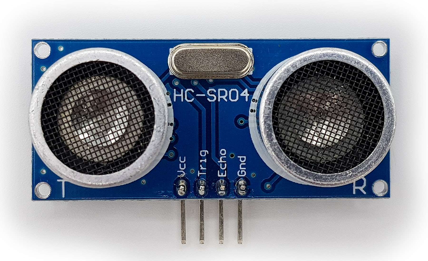
The module has four pins:
- VCC / GND: 5 V are connected here
- Trigger: a change from HIGH to LOW triggers a measurement
- Echo: is HIGH as long as the ultrasonic signal is its way
Exact sequence of a measurement

The trigger input first requires a HIGH signal with a length of at least 10 seconds. The falling edge of the trigger signal is the “starting shot” for the measurement. After approx. 250 µs, the HC-SR04 sends the ultrasonic signal as eight 40 kHz pulses. This process requires about 200 µs. Immediately after sending the signal, the echo pin goes HIGH. It stays on HIGH level until the module receives the reflected signal. After a maximum time of – according to my measurement – about 170 ms, the Echo Pin goes to LOW even without receiving echo. By the way, this would correspond to a distance of 29 m. Measurements in this region can therefore be considered as “no object in range”.
Actually, the Echo pin has to stay on HIGH level until the Echo signal has completely returned, and as this is 200 µs long, this corresponds to a distance of about 3.5 cm. I have not been able to find any information on this detail, but the results are correct and that is the main thing.
Evaluation of the HC-SR04 measurement
The duration of the HIGH state at the Echo pin is measured best using the pulseIn() function. The return value is the time in microseconds.
There is still the conversion of time into distance. In the first approximation, the speed of sound in dry air at room temperature is 343.2 m/s. From the mentioned boundary conditions you can already derive that various factors influence the speed of sound, especially the temperature. The following formula describes the temperature dependency in the range from -20 °C to +40 °C with an accuracy of > 99.8%.
cAir ≈ 331.5 + 0.6 x T[°C] [m/s]
If you insert 0 °C once in this formula and 20 °C once, you can calculate that it makes a difference of at least 3.5%. This is ten times the accuracy of the HC-SR04 specified in the data sheet. Humidity also has an influence. At 20° C, the speed of sound at 100% humidity is 0.375% higher than at 0% humidity. You can neglect other parameters, such as air pressure. If you want to know why this is the case or if you want to know more about the speed of sound in general, then look here on Wikipedia.
The simple conversion formula without temperature correction and after taking the units into account is:
distance [cm] = measuring time [s] * 0.03432 / [cm/µs] 2
The factor of 1/2 is of course because the signal has to travel the distance twice.
The HC-SR04 at Arduino
Sketch for distance measurement
The sketch for distance measurement is no big surprise due to the previous explanations. Compared to the distance measurements with the VL53L0X and VL53L1X from my last post, this is all surprisingly simple.
If you want to take the temperature into account, then comment the corresponding lines.
int triggerPin = 12;
int echoPin = 11;

int cmDistance, tCorrectedCmDistance;
//int temperature = 0;
unsigned long duration;


void setup(){
  pinMode(triggerPin, OUTPUT);
  pinMode(echoPin, INPUT);
  Serial.begin(9600);
  delay(10);
}

void loop(){
  digitalWrite(triggerPin, HIGH);
  delayMicroseconds(10);
  digitalWrite(triggerPin, LOW);
  duration = pulseIn(echoPin, HIGH);

  // Speed of sound in air: 343m/S (at 20°C)
  // 343,2 m/S --> 34,32cm / ms --> 0,03432cm / µs
  // divided by 2 because it's the echo
  cmDistance = duration * 0.03432 / 2;
//  tCorrectedCmDistance = duration *(0.03315 + 0.00006 * temperature)/2;
  Serial.print("Distance [cm]: ");
  Serial.println(cmDistance);
//  Serial.print("T-corrected distance [cm]: ");
//  Serial.println(tCorrectedCmDistance);
  delay(500);
}
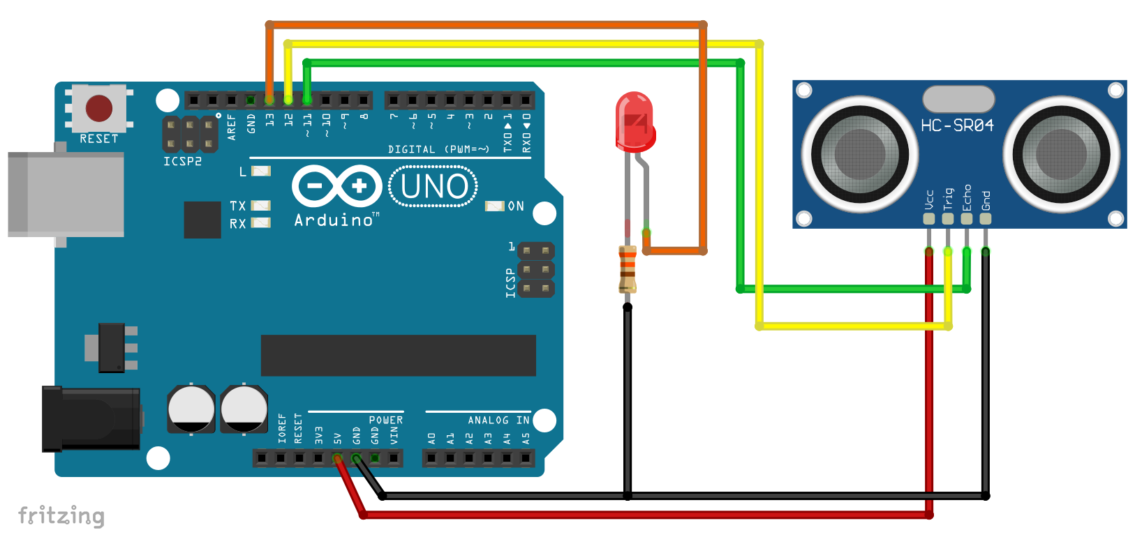
Related circuit
The wiring is also very simple. I need the LED on pin 13 for the motion detector sketch.
Control via NewPing Library
For completeness, I would like to mention that there is a library called NewPing that can be used to control the HC-SR04. You can find it here on Github. However, I am not a friend of using libraries for such simple tasks.
Motion detector sketch
Of course, you can also use any distance sensor as a motion detector. And that’s exactly what the next sketch does. A movement occurs when the current distance value differs by a certain value from the previous value.
int triggerPin = 12;
int echoPin = 11;
int ledPin = 13;
int cmDistancePrevious, cmDistanceCurrent;
const int sensitivity = 20;

void setup(){
  pinMode(triggerPin, OUTPUT);
  pinMode(ledPin, OUTPUT);
  pinMode(echoPin, INPUT);
  cmDistancePrevious = measureDistance();
}

void loop(){
  cmDistanceCurrent = measureDistance();

  if (abs(cmDistanceCurrent - cmDistancePrevious) > sensitivity){
    digitalWrite(ledPin, HIGH);
    delay(1000);
    digitalWrite(ledPin,LOW);
    cmDistanceCurrent = measureDistance();
  }
  cmDistancePrevious = cmDistanceCurrent;
  delay(50);
}

int measureDistance(){
  unsigned long duration = 0;

  digitalWrite(triggerPin, HIGH);
  delayMicroseconds(10);
  digitalWrite(triggerPin, LOW);
  duration = pulseIn(echoPin, HIGH);

  int cmDis = duration * 0.03432 / 2;

  if(cmDis>400){
    cmDis = 400;
  }

  return cmDis;
}
JSN-SR04T-2.0 – the waterproof alternative

Next, I would like to introduce a very interesting alternative to the HC-SR04, namely the JSN-SR04T-2.0. In this case, the transmitter/receiver unit is very compact, waterproof and connected to the module via a 2.5 m extension cable. On the one hand, this makes outdoor applications possible, for example, and on the other hand, the measuring unit can be installed much more discreetly. One restriction to this version is that it requires a minimum distance of 25 cm.
You can get the JSN-SR04T-2.0 for about 10 – 12 euros on Amazon or eBay. If you order from Chinese shops via these platforms, it will be cheaper again, but you may have to be patient with the delivery.
JSN-SR04T vs. JSN-SR04T-2.0 / JSN-SR04T issues
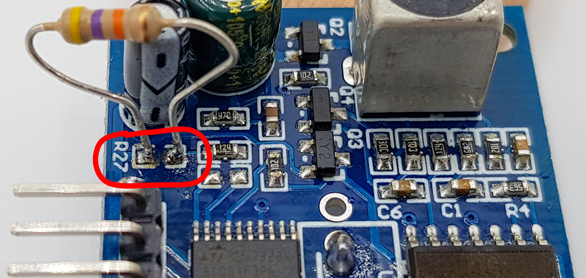
In addition to the JSN-SR04T-2.0, there is also the version JSN-SR04T, i.e. without “2.0”. This looks very similar at first glance, but has a few clear differences. Above all, the JSN-SR04T lacks the jumper R27, which I will come to talk about.
Some JSN-SR04T-2.0 models have problems with incorrect measurements. Sporadically distance values of around 20 cm are determined, although nothing is in this area. I noticed this for one of the three modules I bought. The other two did not show the problem. However, since the error is also described by others (e.g. here) it does not seem to be a seldom exception.
One could be tempted to buy a JSN-SR04T because of these issues. But even if shops have product images of the JSN-SR04T and even if nothing else in the product description refers to version 2.0, you will probably still get version 2.0. In any case, this has happened to me in two out of two attempts. Then I lost my motivation and gave up testing a JSN-SR04T.
Also in this shop here I got the version 2.0, although the other one was pictured. However, I tested this representative most intensively, and it worked without any problems. For this source speaks the absence of negative ratings (as of August 2019).
HC-SR04 vs. JSN-SR04T-2.0
Apart from the differences already mentioned, the JSN-SR04T has the following special features:
- Power supply: 3 – 5.5 V
- Power consumption: approx. 8 mA
- Range: supposedly up to 6 meters
- Detection angle: 45° – 75°; here, too, different data are found – in any case, the angle of coverage is wider than that of the HC-SR04
- Communication: such as the HC-SR04 via trigger / echo or serial (RX / TX)
- Baud rate: 9600, n, 8, 1
The maximum range depends on the size of the object, its surface condition, and the angle of incidence of the signal. I would say that the limit, as with the HC-SR04, is rather 4 meters. With large, smooth walls, for example, you get a little beyond that.
Data sheets for the JSN-SR04T-2.0 are hard to find. Here’s the best I’ve come across.
The three operating modes of the JSN-SR04T-2.0
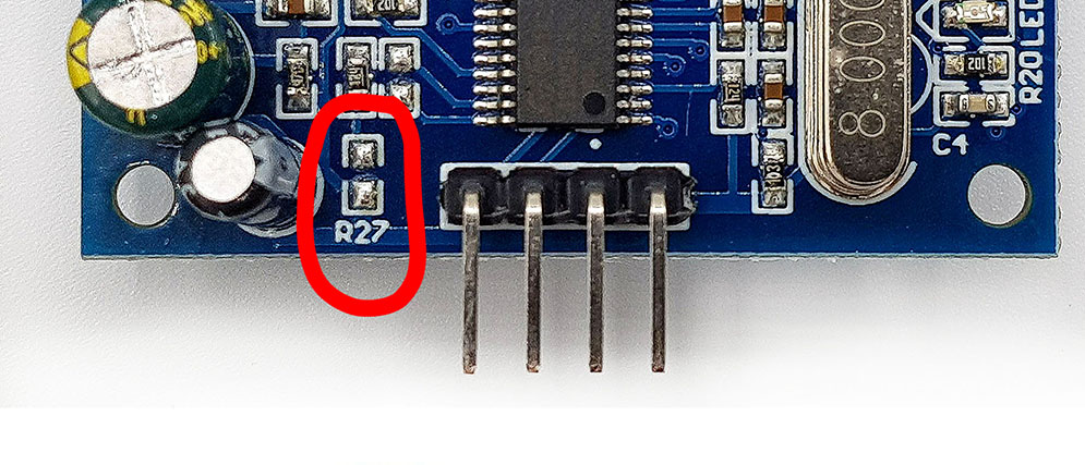
On the module you find the jumper R27 next to the pins. You can leave it unconnected, you can solder a 47 kOhm resistor in between or take a 120 kOhm resistor. With this measure, you determine the operating mode.
Mode 1: R27 open
In this mode, the JSN-SR04T-2.0 behaves like the HC-SR04, which means you control it via the trigger and echo pin. You can use the same Arduino Sketch as the HC-SR04, but with a small change. For every fifth to tenth measurement, I obtained a zero as a result. If you have the same problem, increase the “HIGH time” on the trigger pin from 10 to 20 microseconds (line 18 in HC_SR04_Proximity.ino). With this measure, the error did not occur to me anymore.
Mode 2: 47 kOhm resistance at R27
With a 47 kOhm resistor at R27, the JSN-SR04T-2.0 enters a continuous operating mode. In this mode, a measurement is performed every 100 ms. The result of this measurement is the distance in millimeters, which is transmitted serially as a 16 bit value. The trigger pin becomes RX, the Echo pin becomes TX. The JSN-SR04T-2.0 transmits 4 bytes per measurement:
- Start byte: 0xFF
- Upper byte of distance (h_data)
- Lower byte of distance (l_data)
- Checksum: lower byte of the sum of start byte + h_data + l_data
In my sketch (JSN_SR04T_Serial_continous.ino) the communication takes place via SoftwareSerial. I defined the Arduino pins 10 and 11 as RX pin or TX pin. The RX of the Arduino is connected to TX of the module, TX of the Arduino is connected to RX of the module. I think I can save myself a switching scheme.
If there is data at the serial input, the sketch checks whether it is the start byte. If this is the case, the next 3 bytes are read and stored in an array (“buf”). The distance is then calculated from h_data and l_data. Finally, the sketch checks the checksum. To do this, the upper byte must be masked. If the checksum is OK, the result is output.
I defined the variables h_data, l_data and sum only for didactic reasons. You can also work directly with buf[0], buf[1] and buf[2].
#include <SoftwareSerial.h>
#define rxPin 10
#define txPin 11

SoftwareSerial jsnSerial(rxPin, txPin);

void setup() {
  jsnSerial.begin(9600);
  Serial.begin(9600);
}

void loop() {
  if(jsnSerial.available()){
    getDistance();
  }
}

void getDistance(){
  unsigned int distance;
  byte startByte, h_data, l_data, sum = 0;
  byte buf[3];

  startByte = (byte)jsnSerial.read();
  if(startByte == 255){
    jsnSerial.readBytes(buf, 3);

    h_data = buf[0];
    l_data = buf[1];
    sum = buf[2];
    distance = (h_data<<8) + l_data;

    if(((startByte + h_data + l_data)&0xFF) != sum){
      Serial.println("Invalid result");
    }
    else{
      Serial.print("Distance [mm]: ");
      Serial.println(distance);
    }
  }
  else return;
}
Mode 3: 120 kOhm resistance at R27
Unlike mode 2, mode 3 is a polling method, i.e. a measurement is performed on request. The communication is serial again. A measurement is started by sending 0x55. In the following sketch, a pushbutton triggers this start signal. The “pick up” of the result, on the other hand, is no different from the previous sketch.
#include <SoftwareSerial.h>
#define rxPin 10
#define txPin 11
#define switchPin 9

SoftwareSerial jsnSerial(rxPin, txPin);

void setup() {
  jsnSerial.begin(9600);
  Serial.begin(9600);
  pinMode(switchPin, INPUT);
}

void loop() {
  if(digitalRead(switchPin) == HIGH){
    jsnSerial.write(0x55);
    delay(50);
    if(jsnSerial.available()){
      getDistance();
    }
    delay(1000);
  }
}

void getDistance(){
  unsigned int distance;
  byte startByte, h_data, l_data, sum = 0;
  byte buf[3];

  startByte = (byte)jsnSerial.read();
  if(startByte == 255){
    jsnSerial.readBytes(buf, 3);

    h_data = buf[0];
    l_data = buf[1];
    sum = buf[2];
    distance = (h_data<<8) + l_data;

    if(((startByte + h_data + l_data)&0xFF) != sum){
      Serial.println("Invalid result");
    }
    else{
      Serial.print("Distance [mm]: ");
      Serial.println(distance);
    }
  }
  else return;
}
Acknowledgement
The bat in the post image is taken from Schmidsi on Pixabay.
Has anyone experienced issues using the JSN-SR04T ultrasonic sensor inside a closed underground chamber (such as a manhole, borewell, inspection pit, or underground tank)?
I’m observing inconsistent readings in a confined underground environment (manhole with 2.7 meter depth) and suspect the enclosed space may be affecting the ultrasonic waves (e.g., reflections, echoes, or signal scattering).
Has anyone faced similar problems? If so:
What was the cause?
How did you resolve it?
Are there any recommended sensor placement or filtering techniques for reliable measurements in such environments?
Any insights or practical experience would be greatly appreciated.
Hi, you are not the first who has experienced this issue. You may want to read this discussion:
https://forum.mysensors.org/topic/11417/jsn-sr04t-distance-sensor-reliability-issue-fix
The reason is the wide detection angle of the JSN-SR04T. Unfortunately, I have not found any solution to fix it.
Hi Ewald,
Thanks for your response and for sharing the discussion. I went through it, and it seems the wide beam angle could definitely contribute to the problem.
However, I still have one question. During my testing, the sensor works very well when the manhole lid is open. The distance readings are stable and accurate.
The issue appears only when the lid is closed. In the same manhole (approximately 2.7 m deep), the readings become unstable or completely incorrect. The sensor position and target remain unchanged—the only difference is that the underground chamber becomes a closed space.
Because of this, I’m wondering whether the problem is caused by multiple reflections and echoes inside the enclosed chamber, or whether the sensor itself requires an open air path to operate reliably. In other words, is the JSN-SR04T generally suitable for measurements inside closed underground spaces such as manholes, inspection pits, borewells, or underground tanks?
Has anyone successfully used this sensor in a completely closed underground chamber? If so, were there any specific mounting methods, shielding, or signal-filtering techniques that helped improve reliability?
I’d appreciate any practical experience or suggestions.
Hi Suad, interesting finding that it’s only working if the lid is open. I am struggling to find an explanation. I also think it has something to do with echoes, but, on the other hand, the sound reflected by your target should be detected first (the echo that you want). And if you leave enough time between the measurements, other echoes should not have any impact. Maybe someone else can help?
Thanks for the link to this page via the arduino forum. As other users have said, the english translation works fine and it’s greatly appreciated as it’s WAY better than my schoolboy German (never mind throwing technical words in there).
I like the way the sketch is laid out as it makes complete sense for someone who’s new to arduino programming (me).
Vielen dank
Thank you so much for your kind feedback!
Gern geschehen!
Does mode 2 and 3 also have that dead spot below 20cm?
I need to measure the water level in 1100 liter tubs. But i don’t have that extra space of 20cm. The space in the cover is a out 5 cm. So i was looking for JSN-SR20-Y1 but I ordered it and never arrived 🙁
For a couple of years i used the HC-SR04 but the high humidity always destroy it within a couple of months. I even tried waterproofing it without any success.
Any idea how I can manage to get the reading properly?
The mode only determines the communication with the module but not the measurement itself. So not sure how to solve the problem other than taking the JSN-SR20. I order a lot via Amazon or AliExpress and usually it works fine. Maybe one out one hundred orders get lost or even less even if the things come directly from China. Maybe you try again?
OK, Finally I got the JSN-SR20-Y1. In mode 1, I can’t get proper reading. But in mode 3, it is pretty good. Now I need to figure out the temperature correction formula. Since they send me the distance, I have to find what the speed was and recompute a new distance. Right?
The easiest way is to directly use the duration of the signal:
tCorrectedCmDistance = duration *(0.03315 + 0.00006 * temperature)/2;
I’m desperate.
Ok for the temperature correction. I figured out out to correct it using mode 3. Somehow the duration of the signal is not giving me proper reading. I assumed that I need to remove the resistor that switched it to mode 3. But since it is in a hard to reach place, I tried to solve everything by software.
But…. it goes well for a day or two and then it starts going crazy. For instance it read 24 cm more or less 0.4 very stady. Suddenly it read 30 and back to 24…. for may be 5 minutes, then reads 30 for a few hours. Then, start toggling between 30 and 24 for another 5 minutes or so, then reads properly the 24 again.
It goes like that every day almost, and it is not related to the temperature.
What can cause this? Any idea?
Strange. And problems that do not occur immediately are hardest to find. I don’t have a JSN-SR20-Y1. I have now ordered one, but it comes from China in two weeks. I did not find it on Amazon or eBay. From what I have read so far the JSN-SR20-Y1 should work like the JSN-SR04T-2.0.
Maybe an issue with the module? Do you have a second one to try?
Can you send me the complete sketch you have applied (wolfgang.ewals@wolles-elektronikkiste.de)? And the circuit and/or photos. All information could be useful. Depending on your setup I might be able to replicate it with a JSN-SR04T-2.0. What I know from others is that measurements in constraint space can be difficult because of unwanted echos. But I would expect that to happen immededately and not after a day or two.
I also want to use mode 3 but need the temperature correction. Inm curious to know how you implemented it. Now my values are of bij a few cm and I assume temperature is what’s causing this. The sensor is used in an underground rain water tank to measure the level, so it’s relatively cold there.
For the random variation I use a mean filter. I just take 13 measurements one after the other, sort them and use the center value. This works quite well for me and it has so for over a year now
Don’t expect huge differences between T-corrected and uncorrected values. The formula is in the first sketch. Example: If your echo takes 20000 microseconds to be received the distance is 34.3 cm at 20°C and 33.15 cm at 0°C.
Mhhh that’s not a huge difference indeed for a ∆T of 20°. I’m getting measurements of 2m34 from the sensor where the real value is 2m22. Still would be interesting to know what reference is used internally for the serial mode. Probably something around 20°C?
There is no temperature compensation or reference. The only thing the module does is sending an ultrasonic signal and setting the ECHO pin HIGH when the signal comes back. All calculations have including temperature correction needs to be applied in the software. The deviation must be caused by something else. I know that sidewalls can disturb the measurement.
I’ve got the same problem with JSN-SR20-Y1.
Errating values at fixed time frame. In my case, problem was power supply noise.
I love your in depth posts on sensors to make understanding what makes them tick. Your English posts work fine and appreciate the translations. Look forward to your future work, thats not found elsewhere on these subjects.
Terry
Great motivation for me. Thank you!
Как изменять параметры излучаемого сигнала с датчика JSN-SR04T? Как сделать ЛЧМ, ФКМ сигналы, пачку РИ? Возможно ли это? Как построить спектр сигнала, получаемого после отражения, и его автокорреляционную функцию?
Я не могу сказать, как это сделать. Но я совершенно уверен, что вам придется работать с компонентами, а не с модулем. Здесь возможности ограничены. Надеюсь, этот перевод с DeepL имеет смысл!