About the post
Thanks to the Arduino IoT Cloud (IoT = Internet of Things), some of the Arduino boards can be easily connected to the Internet. Controlling projects and reading data remotely is easily manageable even for beginners.
The Arduino IoT Cloud was introduced to the public in early 2019. I recently tried this offer for the first time and would like to share my experiences with you in this and a subsequent post. Using a practical task, I will show you step by step how to implement a project in the Arduino IoT Cloud. But never forget 😉 :
There is no Cloud – it’s just someone else’s computer!
A not-so-old Internet wisdom
Restrictions and prerequisites for using the Arduino IoT Cloud
I prefer to get to the restrictions and prerequisites at the beginning, so that – if they don’t suit you – you can save time by not read this post!
Board selection
First of all, the Arduino IoT Cloud only works with certain Arduino boards:
- MKR 1000
- MKR WiFi 1010
- MKR GSM 1400
- Nano 33 IoT
- MKR WAN 1300 / 1310
- MKR NB 1500
In the future, the boards MKR Vidor 4000 and Arduino Uno WiFi Rev2 will also be supported. Visit the Arduino pages to have the latest status about the supported models for the Arduino IoT Cloud.
The original Arduino boards are naturally significantly more expensive than cheap China clones. I use a Nano 33 IoT for this post. It costs 16 euros in the Arduino Store (as of May 2020), but taxes and shipping are still on top, so you end up with just over 25 euros. That’s quite some money, but without the originals no clones – so why not support Arduino.
Free Plan vs. Maker Plan
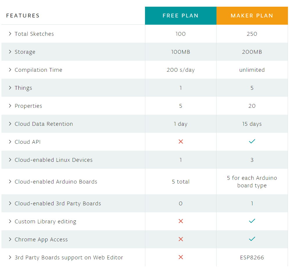
You can use the Arduino IoT Cloud for free, which is called Free Plan. Alternatively, there is the so-called Maker Plan for currently 6.99 dollars per month (can be cancelled at any time) or 5.99 dollars per month for one year. Below you can see the differences, as of May 2020. The only limitation to the Free Plan that really hindered me is the limited compilation time of 200 s/day. If you try a lot, you can reach this limit quickly. So good preparation is required if you don’t want to spend money. In any case, at some point I was ready to invest 6.99 dollars.
Software and user account
You need to create a user account and install the Arduino Create Agent on your computer. We will come to this point later in the step-by-step instructions.
The Arduino Nano 33 IoT board
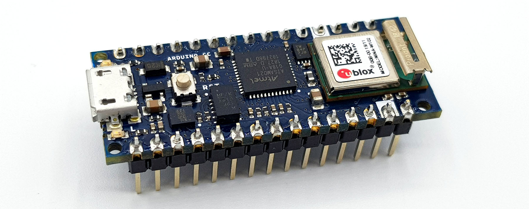
The Arduino Nano 33 IoT has little to do with the original Arduino Nano. It is based on the Low Power, 32 Bit SAMD21 Cortex®-M0+ Microcontroller. Its flash memory is 256 kB in size and the system clock is 48 MHz. It may also require getting used to the output voltage of 3.3 volts.
The Nano 33 IoT has a module for wireless communication via Bluetooth or Wi-Fi. As a nice add-on, the Nano 33 IoT also features a 3-axis accelerometer and gyroscope. Finally, the board – like all Arduino IoT Cloud enabled boards – is equipped with a crypto chip. More technical information can be found here.
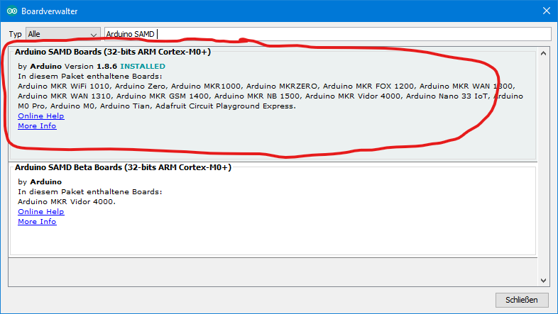
For the Nano 33 IoT to be recognized by the Arduino IDE, you must have the Arduino SAMD boards installed in the board manager. If you need a guide, you can find it on the Getting Started pages.
The task
To explain the principle of the Arduino IoT Cloud, I have selected a basic task: over the Internet, we switch an LED and read out a DHT22 temperature and humidity sensor. Of course, you can take anything else. But you should choose one thing to control and another that you want to read out.
Since online compilation time is precious, you should check your circuit offline. Here is my rather unspectacular offline sketch:
#include "DHT.h"

#define LED_PIN 8
#define DHTPIN 7
#define DHTTYPE DHT22

DHT dht(DHTPIN, DHTTYPE);

void setup(){
  Serial.begin(9600);
  dht.begin();
  pinMode(LED_PIN, OUTPUT);
}

void loop() {
  static unsigned long lastMeasurement = millis();
  float myTemp = 0.0;
  if((millis() - lastMeasurement) > 3000){
    myTemp = dht.readTemperature();
    Serial.print("Temperatur: ");
    Serial.print(myTemp);
    Serial.println(" C");
    lastMeasurement = millis();
    toggleLED();
  }
}

void toggleLED(){
    static bool ledStatus = true;
    digitalWrite(LED_PIN, ledStatus);
    Serial.print("The light is ");
    if(ledStatus){
      Serial.println("ON");
    }
    else{
      Serial.println("OFF");
    }
    ledStatus = !ledStatus;
}
I used the DHT sensor library from Adafruit to control the DHT22 sensor. You can download it here from GitHub or directly via the Library Manager.
And here’s the circuit:

Step-by-Step Guide
The Arduino Web Editor
First, you go to the Arduino Create page. There you can see six tiles. Select the Arduino Web Editor.

If you don’t have an account yet, you’ll be notified and you can create it now. If you are familiar with the Arduino IDE, you should not have any problems with using the online version. It is best you play around with it a little.

Preparing a board for the Arduino IoT Cloud
Go back to the Arduino Create page and select the “Getting started” tile. You’ll see the selection of boards that are suitable for the Arduino IoT Cloud (ESP 8266 should only be visible if you subscribe to the Maker Plan):
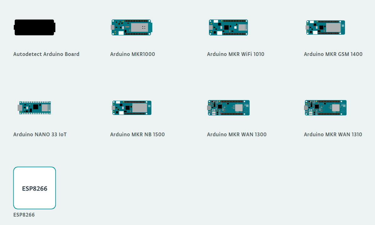
Then you select the board and follow these instructions:
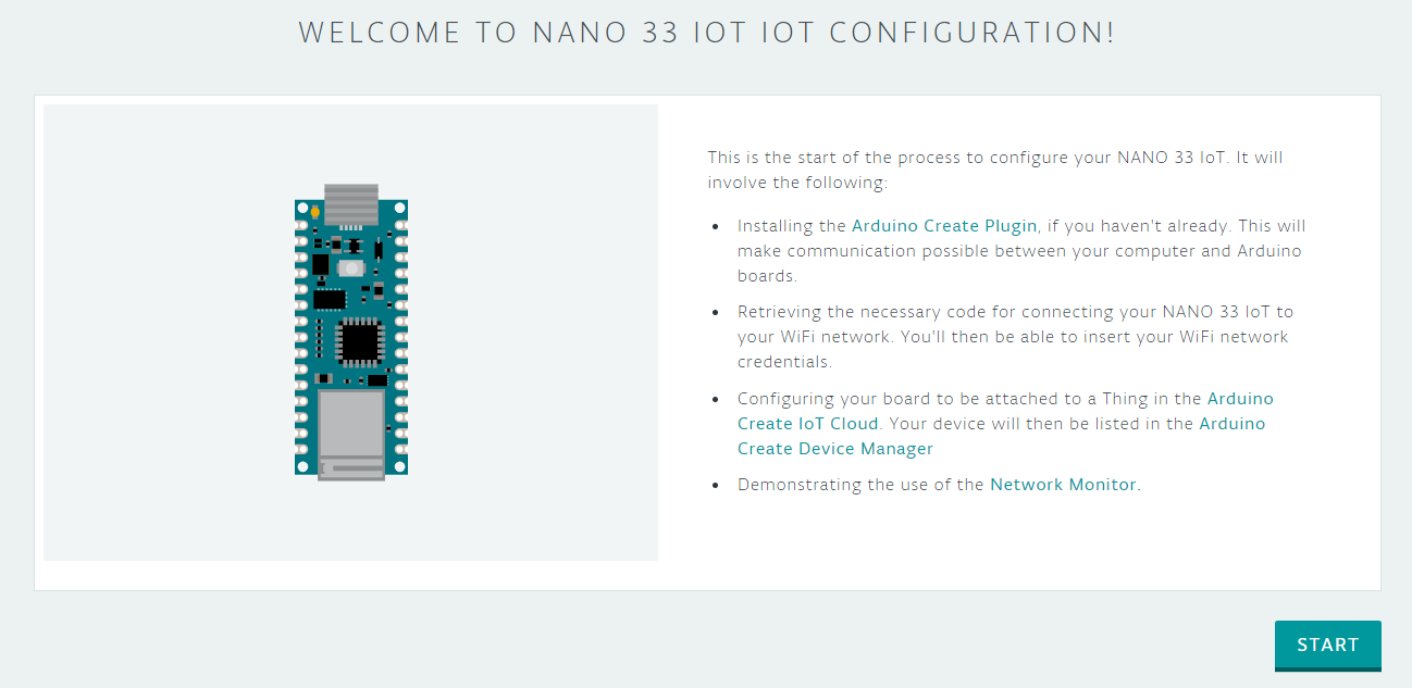
First, you install the Arduino Create plugin. If you were successful with it, you will find the icon in the taskbar. This icon quickly leads you to the Arduino Create page.
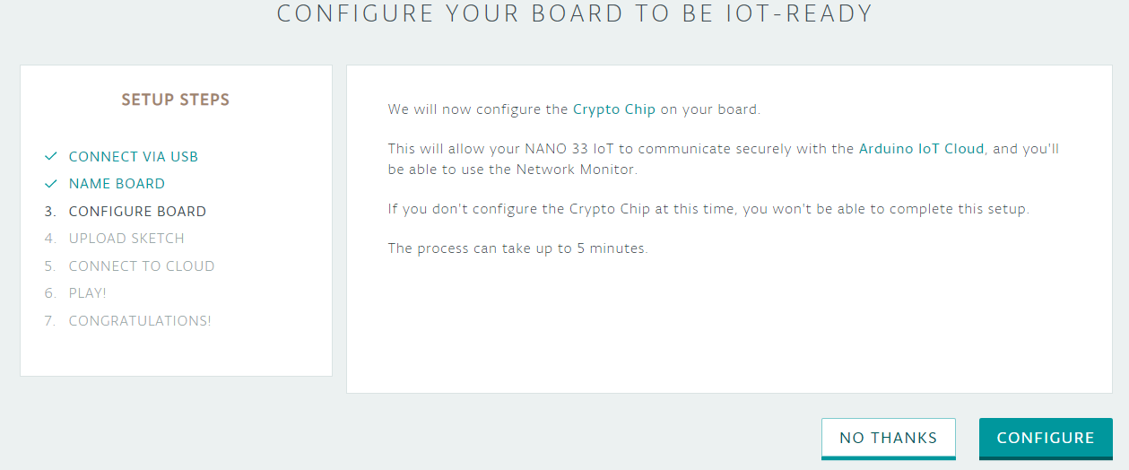
Then the crypto chip is configured:

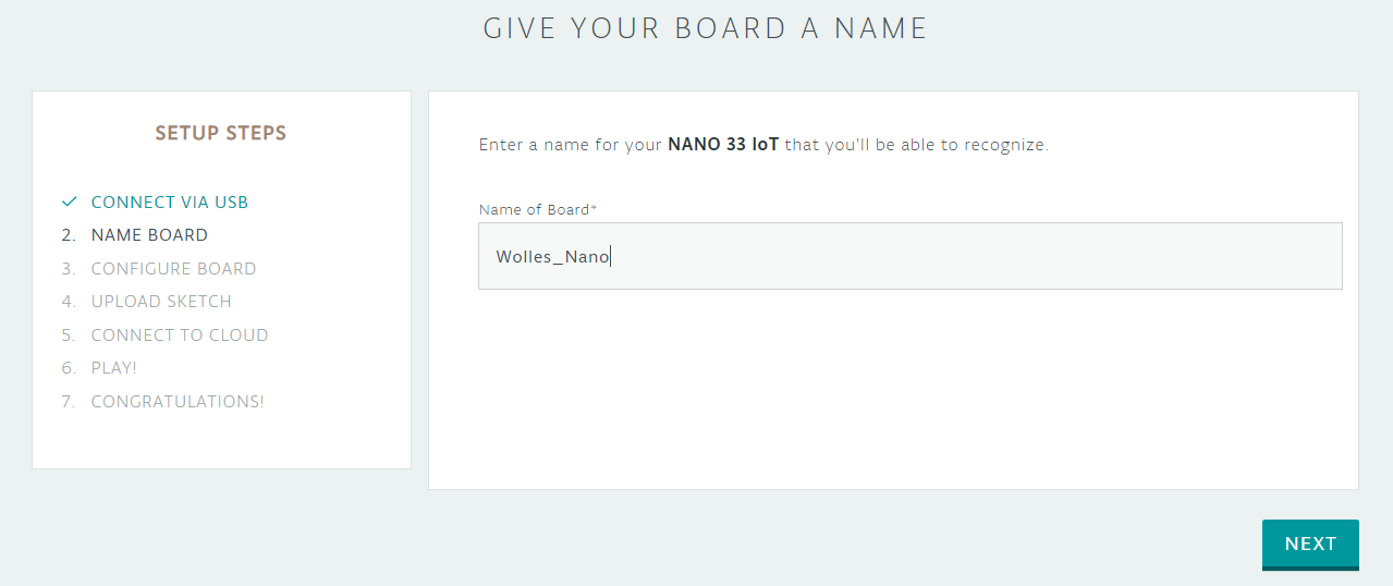
In the next step, you’ll give your board a name:
Click on NEXT and then on CONFIGURE:
The next steps are to set up the Wi-Fi and to test the board.

Enter your Wi-Fi data. SECRET_WIFI_NAME is the name of your Wi-Fi, SECRET_PASSWORD is your Wi-Fi password.

After uploading, you will see the following screen:
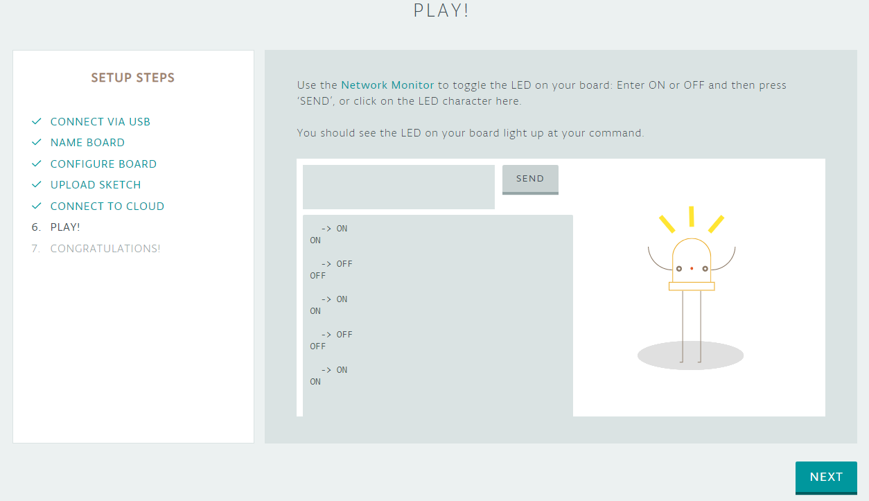
Send “ON” or “OFF” via the text box or click on the LED icon. This will turn on (or off) the on-board LED on the Nano 33 IoT.
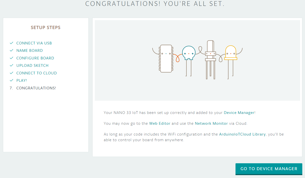
If you now go to the Device Manager (one of the six tiles from the beginning), your board should show up there.
About things and properties
To be able to participate on the Internet of Things, we first need a “thing”. The thing in this example is the board with the sensor and the LED. And for this thing, we need to define properties. But one by one.
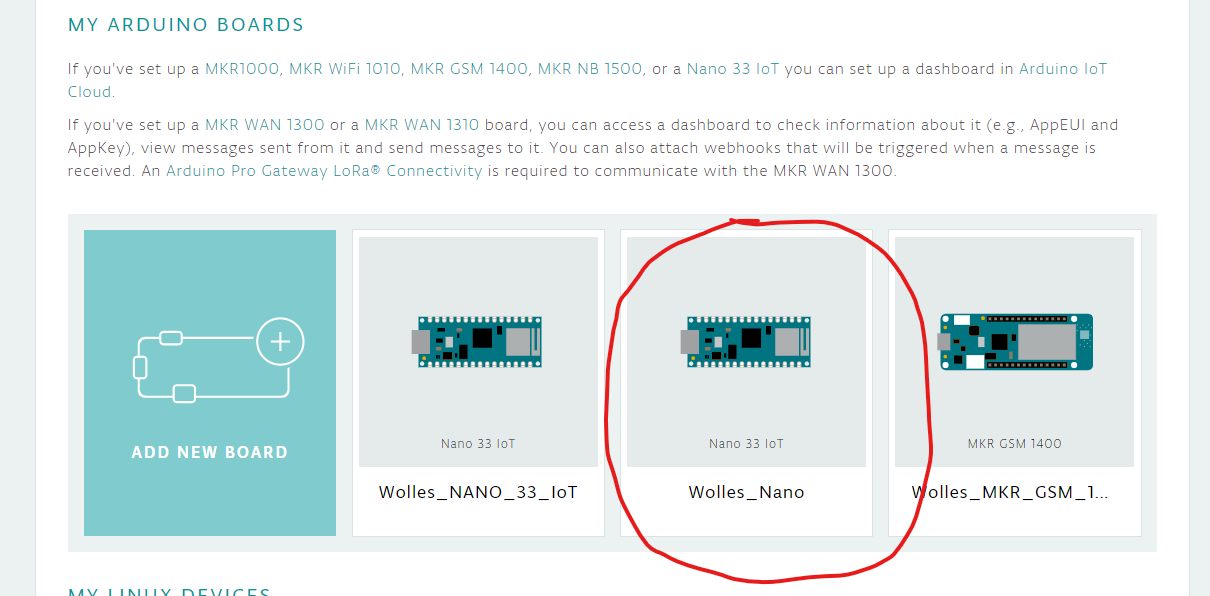
Go back to the six tiles (e.g. via the Create Agent), select “Arduino IoT Cloud” and then “Add new thing”. In the next window, give your thing a name. I chose the very creative name “TestThing” for it. Then you select the previously configured board:

Add the LED as a property
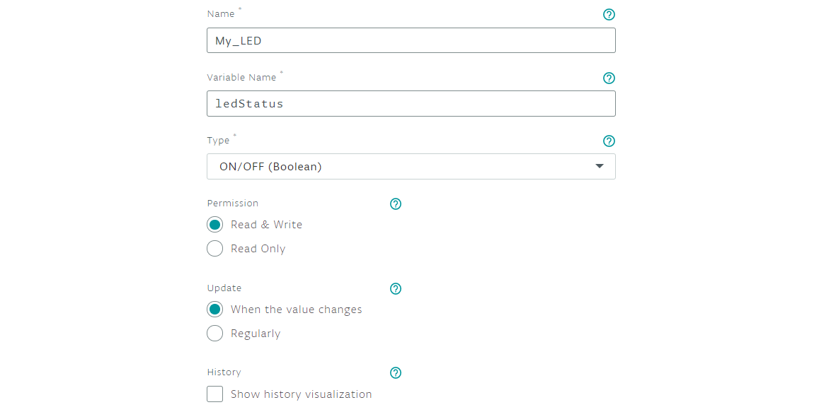
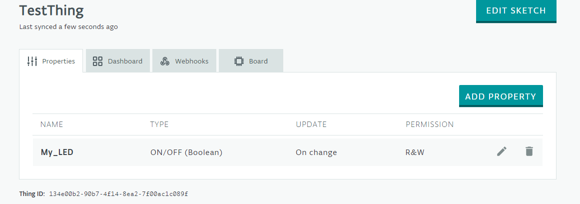
Then you choose “Add Property” and give a name for the first property. I chose “My_LED”, but I have to say in hindsight that “Light” or the like would have been more appropriate because an LED is not a property in itself. But it doesn’t matter. Then choose a variable name and select a type. In this case, ON / OFF fits, i.e. boolean.
Depending on whether you want to control or read something, you give permission to read and modify the variable, or just read it. For the LED we need “Read and Write”. Update sets the conditions for updating the variable, which is the property. Either the update occurs when the value is changed or at a specified interval. A tick in the “History Visualization” check box enables you to track the latest changes of the value.
Then select “ADD PROPERTY”. In the overview of your thing you can now see the property:
Add the temperature as a property
Now let’s repeat the procedure for the temperature. As type, I chose “Float”. Only later did I realize that I could have chosen “Temperature”. But frankly I didn’t want to go through everything again, with all the screenshots etc….
Min and Max Value are used for graphical representation where the current value is within the limits. Later you will see what that looks like. The temperature should only be read, so it is “read only”. Changes in temperature should only be shown if the delta is greater than or equal to 0.1 degrees.

Select “ADD PROPERTY” again.
You may have noticed the “New Dashboards” option at the bottom of the screen. I will also come back to this later.

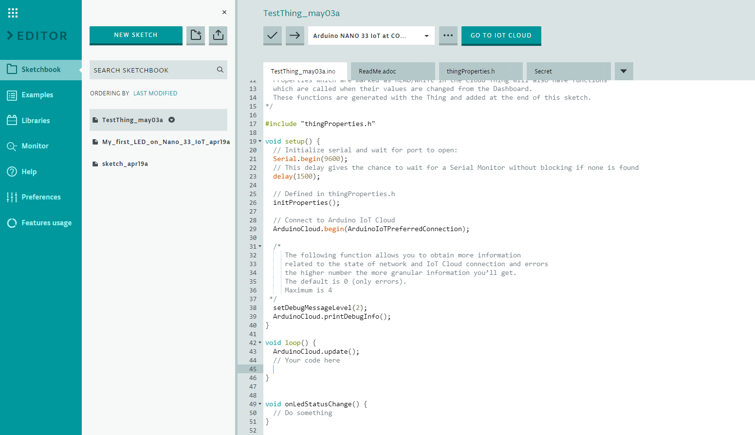
Customize the Sketch
Now click on “EDIT SKETCH”. You will find yourself in the Arduino Web Editor and see prepared sketch that you just need to customize. In the onLedStatusChange function, you specify what should happen when the variable changes ledStatus. Since you only read out the temperature, you don’t need to add anything.
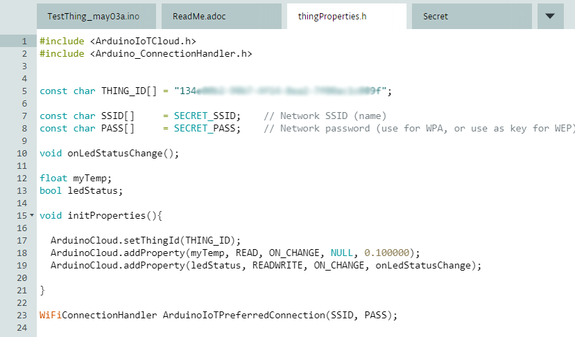
Now take a look at the thingProperties.h tab. You can see that there are additional, necessary header files included. The THING_ID is a unique ID to identify your thing. It is also used to access your thing with other internet services from outside.
SSID and PASS are the Wi-Fi name and the Wi-Fi password. You have to enter them again in the “Secret” tab.
Then you will notice that the variables of your properties have already been declared automatically. You can also see how the properties of your thing are added to the code with the parameters you have selected ( ArduinoCloud.addProperty(….)code> ).
Now you complete the prepared sketch. You define how the value of the myTemp variable should be determined and how often this happens. Then you add what should happen when the variable ledStatus is changed.
This is what the sketch finally looks like:
#include "thingProperties.h"
#include "DHT.h"

#define LED_PIN 8
#define DHTPIN 7
#define DHTTYPE DHT22

DHT dht(DHTPIN, DHTTYPE);


void setup() {
  Serial.begin(9600);
  delay(1500);
  dht.begin();
  pinMode(LED_PIN, OUTPUT);

  initProperties();

  ArduinoCloud.begin(ArduinoIoTPreferredConnection);

  setDebugMessageLevel(2);
  ArduinoCloud.printDebugInfo();
}

void loop() {
  static unsigned long lastMeasurement = millis();

  ArduinoCloud.update();

  if((millis() - lastMeasurement) > 3000){
    myTemp = dht.readTemperature();
    Serial.print("Temperatur: ");
    Serial.print(myTemp);
    Serial.println(" C");
    lastMeasurement = millis();
  }
}


void onLedStatusChange() {
    digitalWrite(LED_PIN, ledStatus);
    Serial.print("The light is ");
    if (ledStatus) {
        Serial.println("ON");
    } else {
        Serial.println("OFF");
    }
}
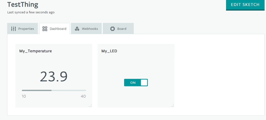
Now you can compile and upload the sketch. On the serial monitor you can check whether the temperatures are read out correctly. Then click on GO TO IOT CLOUD, then on the “Dashboard” tab. There you will see one tile for the current temperature and another for switching the LED. That’s it – now you can access it from anywhere in the world.
Make it more beautiful with the “New Dashboards”
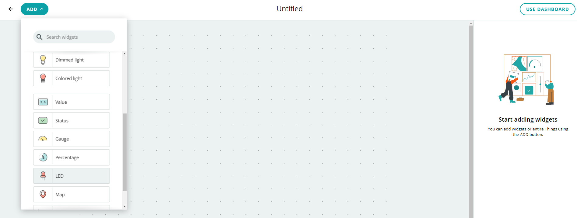
Now let’s go back to the “New Dashboards” mentioned above. There you select CREATE DASHBOARD, then ADD. There is a widget for LEDs:
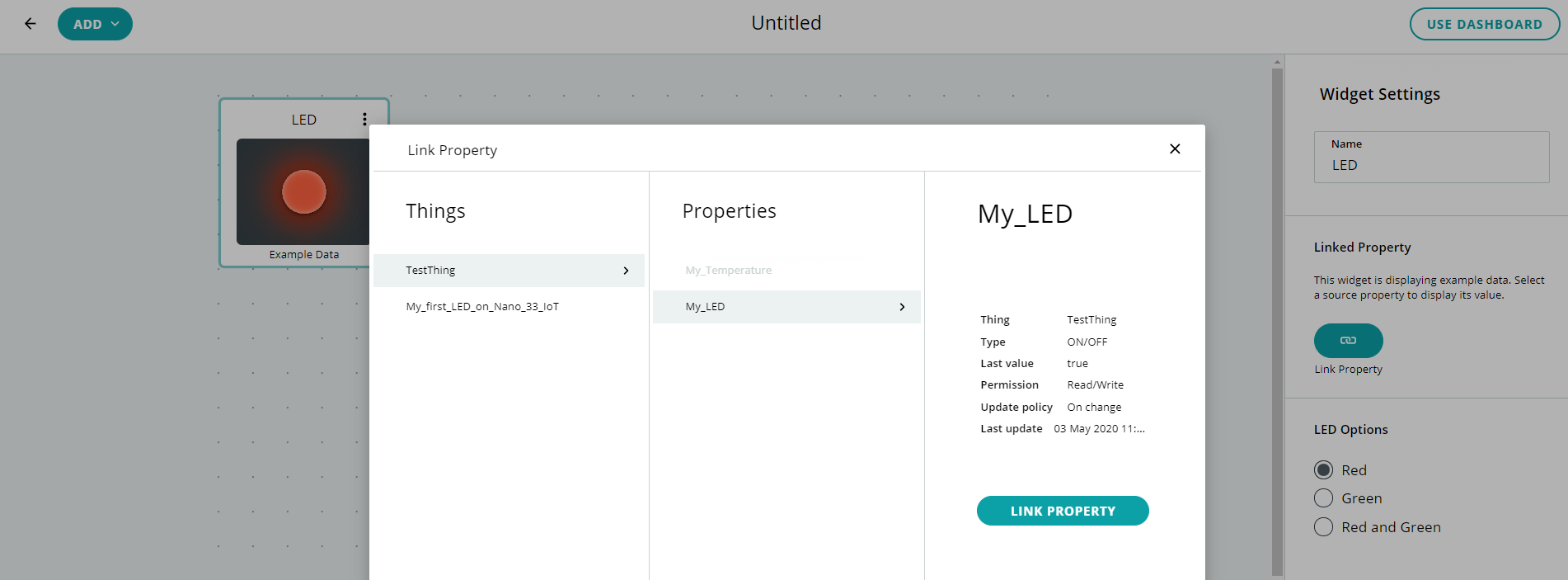
Select the widget and drag it where you want it to be. Then you have to link it to a property, i.e. to My_LED:
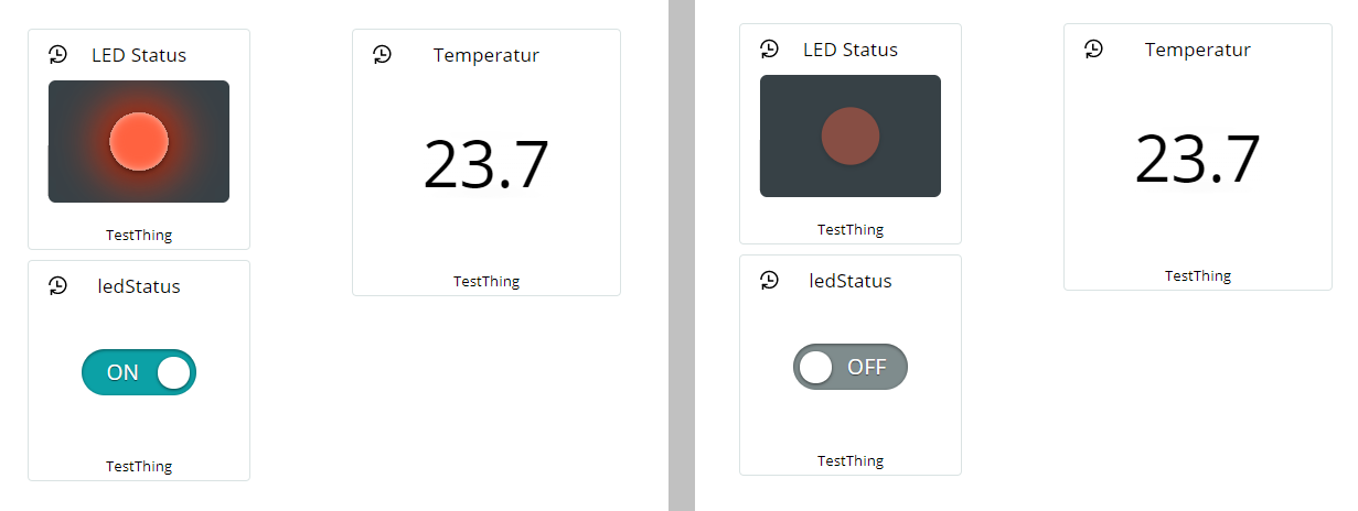
The widget only shows the status of the LED. To switch the LED, add a switch. Then you add a widget for the temperature to the dashboard. Here’s what the result is:
Access with your smartphone
Apparently, access to the “New Dashboards” from the smartphone is not (yet) planned, although this is really a functionality that most people certainly want. Anyway, I haven’t found a “New Dashboard” button in the smartphone view. If this is also the case with you, then simply enter the URL from the PC manually in your browser on your smartphone. You’ might need to move the widgets a bit to display them completely on the smartphone screen.
This is what it looks like for me:
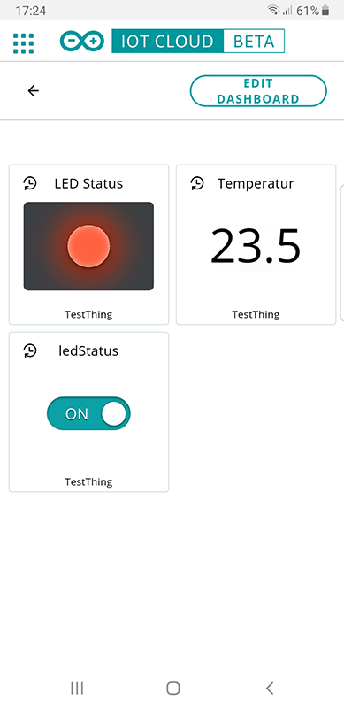
Then you can create a link to the dashboard on your smartphone’s home screen and have quick and convenient access.
Alternative to the Arduino IoT Cloud
How you switch an LED via browser and read out a temperature, I had already described in my post about the ESP8266 ESP-01. If you use the module in your home network and can access it via VPN, you have – in terms of the functionality presented so far -basically an equivalent, secure solution, but without expensive board and restrictions on compilation time.
One drawback of the ESP8266 solution is that you also need to be a little familiar with HTML and CSS to make the whole thing visually appealing. In addition, certain Arduino boards can also be connected to the Arduino IoT Cloud via a 3G connection. Thus, you are independent of the presence of Wi-Fi.
In addition, the Arduino IoT Cloud offers some convenient ways to connect to other Internet services that I haven’t talked about yet.
Outlook
Among other things, I have not yet addressed the interesting topic of webhooks at all, as it would go beyond the scope of this article. You may have noticed the corresponding tab in the TestThing overview. With webhooks, you can do things like email you if sensor values take on critical values. I plan to address this in one of my next posts, as well as the mentioned 3G connection of Arduino boards to the Arduino IoT.