About the post
Please note: Unfortunately, the manufacturer of the aTeVaL 2.0, eHaJo, is closing its online store at the end of 2023. The aTeVal 2.0 is unfortunately already no longer available. Too bad!
In this post I would like to introduce you to the aTeVaL 2.0 board that I came across some time ago and which I think is a pretty ingenious invention. In particular, I recommend it to those who want to look beyond the world of Arduino and look into the C programming of various microcontrollers, for example via Atmel Studio (Microchip Studio since 2020) – hence the ladybug in the post picture, a ladybug is the logo of the program.
To program the bare AVR microcontrollers via Atmel Studio, you have to use special and sometimes expensive programmers. In addition, there is some wiring work if you want to switch between the Arduino and the Atmel Studio world. And that’s where the aTeVaL 2.0 board comes in. With the board, you can do the following (among others):
- Simulate an Arduino UNO and program your MCU with the Arduino IDE
- Program various other AVR microcontrollers with the Arduino IDE
- Program all AVR microcontrollers directly with Atmel Studio
- Switch between the Arduino IDE and Atmel Studio without much wiring.
- Test sketches with the buttons, LEDs, potentiometers and buzzer integrated on the board
- Switch conveniently between 5.0 and 3.3 volt output voltage.

I would like to note that I have no economic benefits from recommending the aTeVaL 2.0 board. I’m just really excited about this nice device!
Preparations
Where to get the board
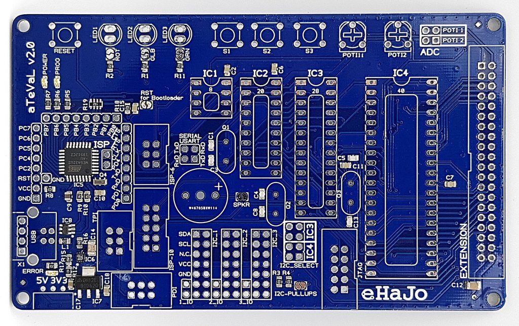
The aTeVaL 2.0 (probably for Atmel Evaluation) is manufactured by eHaJo in Bavaria. “Made with love and brain in Bavaria” can be read on the back of the board. It is only available as a kit, but if you have a soldering iron and no two left hands, the board is easily assembled in 30 minutes. All SMD components are pre-soldered. You get the board for 29.90 euros plus shipping (as of April 2020). I ordered two of them and both arrived at me well packed within a few days.
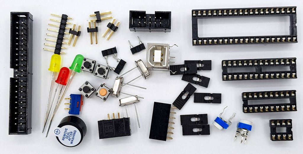
Microcontrollers are not included, you have to order them separately. The main ones are also available from eHaJo – this saves shipping costs. In any case, I recommend you to purchase an ATmega328P or several. Importantly, it is the “P” variant if you want to program the aTeVaL via Arduino IDE. You can also use the ATmega328P from your Arduino UNO if you have one.
The assembly
For assembly there is a nice video from the manufacturer here on YouTube. There are also some very helpful tips for soldering. As already mentioned, this is all simple, but don’t do it in a rush and check after the first soldering connection twice if everything is plugged in correctly. You can desolder one connection easily, but once you have completely and incorrectly soldered the 40-pin connector, for example, it’s hard to change.
There are a few solder jumpers on the board, for example the ones for the LEDs or the bootloader. I recommend connecting them all.
“Feet” for the board are not included. As you can see above, I used spacers for this. There is also no housing, but in my view this would make no sense anyway since almost the entire board must be accessible.
Driver installation
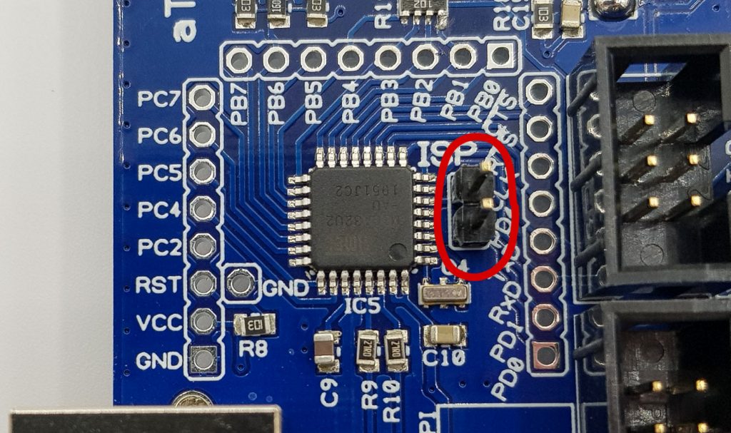
Drivers are often a rich source of problems – but not here! On the Dokuwiki pages of the manufacturer you will find both instructions for the installation and the drivers themselves. Depending on whether you place the jumper “ISP” next to the ATmega32U2 (the IC with the 32 leges), the aTeVaL behaves like an ISP programmer or like a serial programmer. A driver is required for both settings. Just follow the instructions. I do not have to describe this again here, as it is already very well described.
Plugging in a microcontroller
Plug the microcontroller of your choice into the right socket. Only one microcontroller can be used at a time because the ISP lines are connected to all IC sockets (and for some other reasons). So, you can’t “switch.” Plugging in the MCUs should always be done carefully. With new microcontrollers, you need to bend pins a little in advance. Removing them can also be a bit tricky – I recommend IC pliers for this.
Integrating the aTeVaL 2.0 board into the Arduino IDE
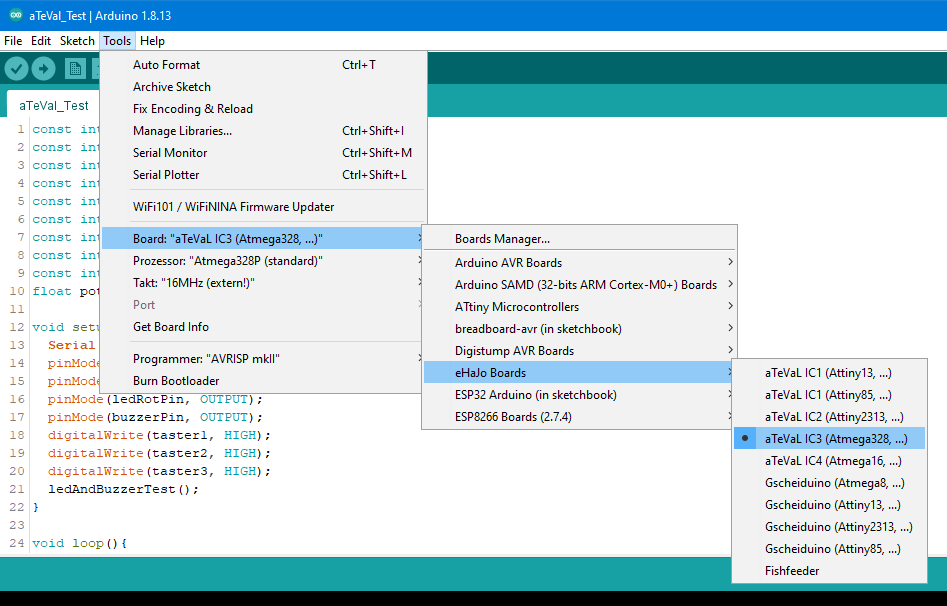
The aTeVaL 2.0 enables you to program various AVR microcontrollers with the Arduino IDE, not just the ATmega328P. But you have to “teach” the Arduino IDE first. All you need to do is add the line “https://www.ehajo.de/dokuwiki/_media/package_ehajo_index.json” in the presets of the board managers URLs and install the eHaJo boards in the board manager. Just search for “ehajo” there. If you’ve done this before, this information should be enough. If not, you can find detailed instructions here at eHaJo. If you were successful, you should see the board in the tools menue after restarting the Arduino IDE.
Quickstart
The aTeVaL 2.0 as Arduino UNO
The board is assembled, the drivers are installed, the boards are integrated into the Arduino IDE – now you can start. First, I want to show you how the aTeVaL 2.0 can be used as Arduino.
Burning the Arduino UNO bootloader
If you don’t know what a bootloader is and what you need it for, i recommend this YouTube video from eHaJo. I haven’t found such a clear explanation anywhere, even for beginners – worth seeing.
First, the Arduino bootloader has to be burned on the ATmega328P if you want to use the board as Arduino. This can only be done in ISP mode. Follow these steps:
- plug an ATmega328P into the 28-pin IC socket
- the ISP jumper must be set so that the board can be used as a programmer
- set the Serial USART Jumper (next to the buzzer)
- put the 16 MHz oscillator into the socket next to C4 and C18
- connect the board to the PC via USB
- you don’t see any port in the tools (the entry is light gray) – this is no wonder because the card as ISP programmer is not a serial port
- select the Arduino UNO as board in the Arduino IDE
- as a programmer, you choose the “AVRISP mkII”
- navigate to Tools — > Burn bootloader; after a few seconds the success message should appear
Uploading an Arduino sketch and testing the board
Now you leave the ISP mode by disconnecting the aTeVaL from the PC, removing the ISP Jumper and reattaching the board to the PC. If you go into tools now, Port should no longer be grayed out. Choose the port. “Arduino UNO” should still be set as a board and “AVRISP mkII” as programmer. Now you can upload sketches the normal way.
If you have connected all the solder jumpers and set the potentiometer jumpers, the board will behave according to the following Fritzing scheme:
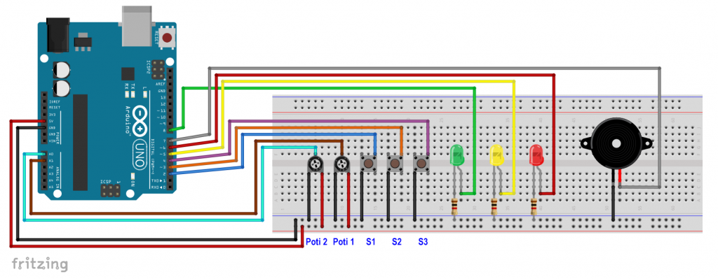
The following sketch tests the buttons, LEDs, potentiometers and the buzzer integrated on the aTeVaL board. I don’t think the sketch needs much explanation, except perhaps line 40: if((millis()%1000)==0). The condition becomes true once per second for one millisecond, i.e. once per second the potentiometer values are output. A nice alternative to delay constructions because they would interfere with the query of the buttons.
const int poti1Pin = A1;
const int poti2Pin = A0;
const int ledGruenPin = 8;
const int ledGelbPin = 5;
const int ledRotPin = 6;
const int buzzerPin = 7;
const int taster1 = 2;
const int taster2 = 3;
const int taster3 = 4;
float poti1Voltage, poti2Voltage = 0;

void setup(){
  Serial.begin(9600);
  pinMode(ledGruenPin, OUTPUT);
  pinMode(ledGelbPin, OUTPUT);
  pinMode(ledRotPin, OUTPUT);
  pinMode(buzzerPin, OUTPUT);
  digitalWrite(taster1, HIGH);
  digitalWrite(taster2, HIGH);
  digitalWrite(taster3, HIGH);
  ledAndBuzzerTest();
}

void loop(){
  if(!digitalRead(taster1)){
    digitalWrite(ledRotPin, HIGH);
    delay(1000);
    digitalWrite(ledRotPin, LOW);
  }
  if(!digitalRead(taster2)){
    digitalWrite(ledGelbPin, HIGH);
    delay(1000);
    digitalWrite(ledGelbPin, LOW);
  }
  if(!digitalRead(taster3)){
    digitalWrite(ledGruenPin, HIGH);
    delay(1000);
    digitalWrite(ledGruenPin, LOW);
  }
  if((millis()%1000)==0){
    poti1Voltage = analogRead(poti1Pin)/1023.0 * 5.0;
    Serial.print("Poti 1 [V]: ");
    Serial.print(poti1Voltage);
    poti2Voltage = analogRead(poti2Pin)/1023.0 * 5.0;
    Serial.print("  /  Poti 2 [V]: ");
    Serial.println(poti2Voltage);
  }
}

void ledAndBuzzerTest(){
  digitalWrite(ledGruenPin, HIGH);
  delay(500);
  digitalWrite(ledGelbPin, HIGH);
  delay(500);
  digitalWrite(ledRotPin, HIGH);
  tone(buzzerPin, 1000);
  delay(2000);
  digitalWrite(ledGruenPin, LOW);
  digitalWrite(ledGelbPin, LOW);
  digitalWrite(ledRotPin, LOW);
  noTone(buzzerPin);
}
Connect more pins
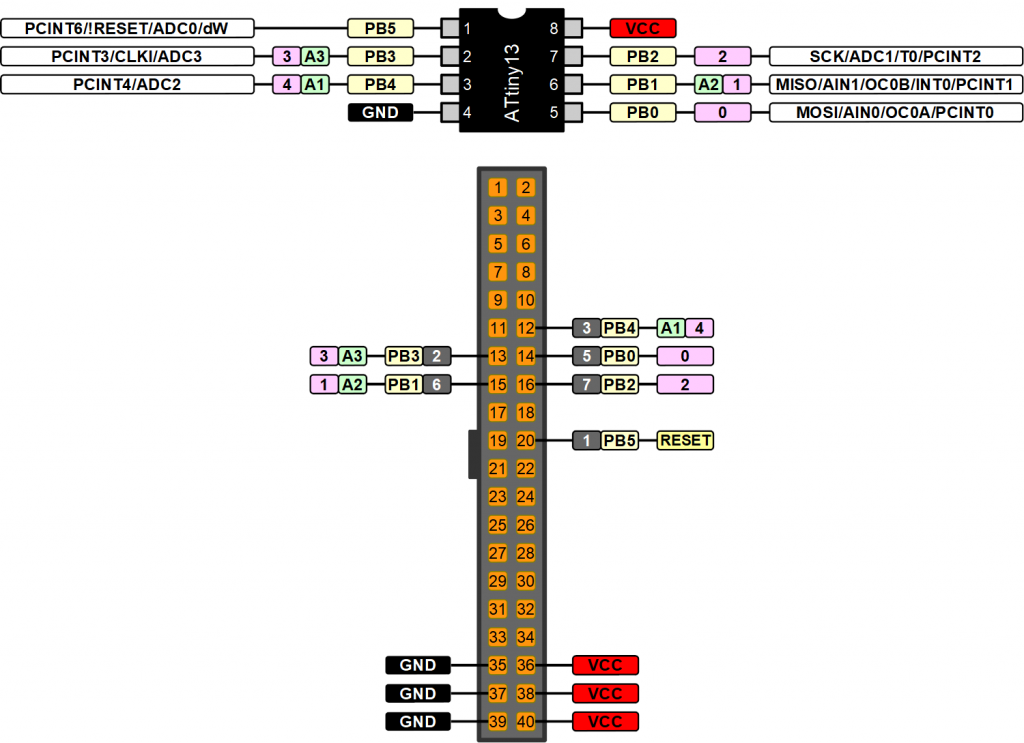
All I/O pins of the ATmega328P are also connected to the 40-pin header connector. Which pin is connected to which pin of the ATmega328P can be seen in the following schematic:
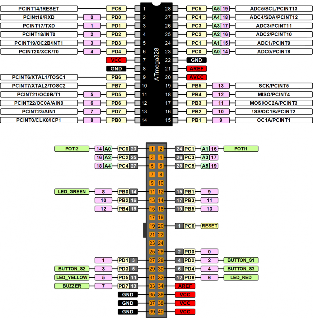
If you use an 8-pin MCU such as the ATtiny85, a 20-pin one like the ATtiny2313 or 40-pin one like the ATmega16, other schemes apply, which you can find here.
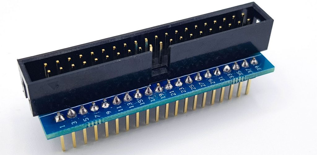
Using the breadboard adapter
If you connect the pins of the 40-pin header to a breadboard with jumper cables, then you can easily get confused. I recommend ordering a breadboard adapter and a suitable ribbon cable together with the aTeVaL board. You can find both here for 4.80 Euro plus shipping (as of April 2020) – it’s worth it.
Atmel (Microchip) Studio with the aTeVaL 2.0
Atmel Studio is a free IDE (development environment) from Microchip, the manufacturer of the AVR microcontrollers. You can download the program here. Atmel Studio is much more complex than the Arduino IDE, but it’s much more powerful, too. You can find an introduction written by me here. In this article, I can only outline in broad terms what you need to do. Anything else would go beyond the scope.
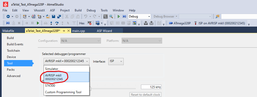
If you have installed the driver for the aTeVaL as ISP programmer, Atmel Studio should recognize it without problems. For me, it worked on the first try. Of course, you must have set the ISP Jumper.
However, there is a limitation compared to expensive programmers like the Atmel-ICE or the AVR Dragon. DebugWire programming is not possible.
Setting the Fuse Bits
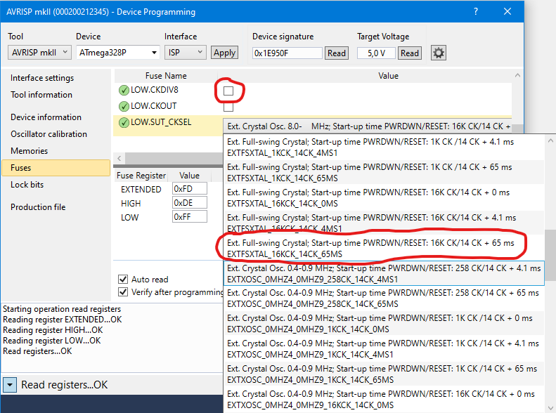
A fresh microcontroller has certain presets, such as clock frequency, clock source, or clock divider. You can change these presets in the “Device Programming” section (Ctrl + Shift + P). However, a little caution is required when choosing settings. With wrong settings, you can easily lock yourself out and then only get back in with special programming devices like the AVR Dragon.
As an example, I show how to prepare the ATmega328P for 16 MHz with external oscillator. In this case, you need to remove the tick of the box for the clock divider (LOW. CKDIV8) if it was set and choose the correct setting for the oscillator:
A test program for the ATmega328P
Also for Atmel Studio I wrote a small program to test the buttons, LEDs etc. integrated on the board. It works slightly differently than the Arduino test sketch because there is no serial monitor available to output the potentiometer values. Instead, the buzzer frequency is set here via the potentiometer values. Just try it out. The control is done via the timer1 – maybe one or the other has read my article on this topic.
However, I do not want to go into the further details of the program code here. Instead, I refer you to the well-commented C program examples at eHaJo.
If you don’t have any experience in C programming, you may find this quite daunting. But it’s less hard than you think. It looks just a little cryptic. Basically, it is like working with a control panel and you just need to know the individual switches and use them in the correct order. For beginners, I recommend this book or my post on binary logic and port manipulation as a place to start.
#include <avr/io.h>
#include <util/delay.h>
#include <avr/interrupt.h>

#define F_CPU		16000000UL
#define LED_GRUEN	(1<<PB0)
#define LED_GELB	(1<<PD5)
#define LED_ROT		(1<<PD6)
#define TASTER1		(1<<PD2)
#define TASTER2		(1<<PD3)
#define TASTER3		(1<<PD4)
#define BUZZER		(1<<PD7)


int main(void)
{
  uint16_t poti1Wert, poti2Wert;

  DDRB |= LED_GRUEN;
  DDRD |= BUZZER | LED_ROT | LED_GELB;
  PORTD |= TASTER3 | TASTER2 | TASTER1;
  TIMSK1 |= (1<<OCIE1A);
  ADCSRA |= (1<<ADEN);
  ADMUX |= (1<<REFS0);
  ADCSRA |= (1<<ADPS2) | (1<<ADPS1) | (1<<ADPS0) ;
  ADCSRA |= (1<<ADSC);

  while (ADCSRA & (1<<ADSC))
  {}
  poti1Wert = ADCW;

  sei();

    while (1)
    {
    ADMUX &= ~(1<<MUX0);
    ADCSRA |= (1<<ADSC);
    while (ADCSRA & (1<<ADSC))
    {}
    poti2Wert = ADCW;

    ADMUX |= (1<<MUX0);
    ADCSRA |= (1<<ADSC);
    while (ADCSRA & (1<<ADSC))
    {}
    poti1Wert = ADCW;

    if(!(PIND & TASTER1))
    {
      PORTB |= LED_GRUEN;
      OCR1A = 5000 + poti1Wert*16;
      TCCR1B |= (1<<CS10) | (1<<WGM12);
    }

    else if(!(PIND & TASTER2))
    {
      PORTD |= LED_GELB;
      OCR1A = 5000 + poti2Wert*16;
      TCCR1B |= (1<<CS10) | (1<<WGM12);
    }

    else if(!(PIND & TASTER3))
    {
      PORTD |= LED_ROT;
    }

    else if(PIND & (TASTER1 | TASTER2 | TASTER3))
    {
      PORTB &= ~LED_GRUEN;
      PORTD &= ~LED_GELB;
      PORTD &= ~LED_ROT;
      TCCR1B = 0;

    }
    }
}

ISR(TIMER1_COMPA_vect)
{
  PORTD ^= BUZZER;
}
Use other microcontrollers with the Arduino IDE
One of the advantages of the aTeVaL 2.0 is that you can program other microcontrollers directly using the Arduino IDE in addition to the ATmega328P. You can find the selection under Tools –> Board: … –> eHaJo Boards –> aTeVaL Boards. In addition to the ATmega328P, I tried the ATtiny85 and the ATtiny2313 and both worked wonderfully.
Unfortunately, I had problems with the 40-pin ATmega16. There was an error message when compiling (regardless of sketch):

Example: Programming the ATtiny85 with the aTeVaL 2.0
First, you need to insert the ATtiny85 (the right way around!) into the socket for the 8-pin microcontrollers. The programming is done via ISP, so you set the jumper. In the Arduino IDE, you choose ATtiny85:

As a programmer, you set the AVRISP mkII again. I have chosen “8 MHz (internal)” as clock. To try out, take a simple blink sketch like this one:
void setup() {
// 4 = PB4 = Pin Nr. 3 auf ATtiny85 = Pin Nr. 12 auf dem 40 pol. Wannenstecker
  pinMode(4, OUTPUT);
}

void loop() {
  digitalWrite(4, HIGH);
  delay(1000);
  digitalWrite(4, LOW);
  delay(1000);
}
When using an 8-pin microcontroller, it is unfortunately not connected to any of the on-board LEDs. So, you have to connect one externally and use the corresponding initial scheme:
Then upload the sketch via “Upload with Programmer” or Ctrl + Shift + U. If you use a fresh ATtiny85, the LED will most likely flash not with 1 Hz, but with 1/8 Hz. If you choose 1 MHz instead of the 8 MHz clock frequency, things are fine again. In the Arduino IDE you choose the clock frequency set in the microcontroller, but you do not change it.
How do I change the clock frequency?
You can easily change the clock with Atmel Studio, even if you are not familiar with the program yet: Start Atmel Studio –> Ctrl + Umsch + p –> Select tool –> Select Device –> Apply –> Fuses –> Remove the tick in the clock divider box –> click on “Program”. The LED will flash at the right frequency.

Back in the Arduino IDE you can now choose 1 MHz as a bar and see what happens.
Acknowledgement
Once again I used some pictures of Pixabay as the basis for my post picture:
- The hands with the puzzle pieces are from PublicDomainPictures
- I owe the ladybug to Amanda Elisabeth
- The Arduino, which I have used several times before, has been made available to Seven_au
I would like to thank the company eHaJo for the development of this great board, the prompt answering of technical questions and the permission to use some schemes.
Thank you a lot for this information.
I bought the card, mounted it and it works perfectly.
I used it to burn an ATmega328, with and without a bootloader, very easily.
I burn also an ATtiny85, and it worked well.
All with the Arduino environment.
eHaJo should have more information in english, since what they develop is great.
Thank you again for all your pages, Bernard.
Great thanks for the feedback. And yes, this thing is really amazing.