About the post
In this article, I would like to introduce methods of controlling an LED dot matrix display. This is not the first article about this topic on the net, of course, but perhaps there is still some new things to discover for you. Specifically, I will cover the following:
- What is an LED dot matrix display, and how does it work?
- Direct control with an Arduino
- Control via the MAX7219 / MAX7221 (with library)
- Using displays with built-in MAX7219
- Programming a ticker
- Control via the MAX7219 / MAX7229 without library
- Appendix: Controlling a bi-color, TA6932-based matrix display
As an appetizer here I have a short video :
What is an LED dot matrix display and how does it work?
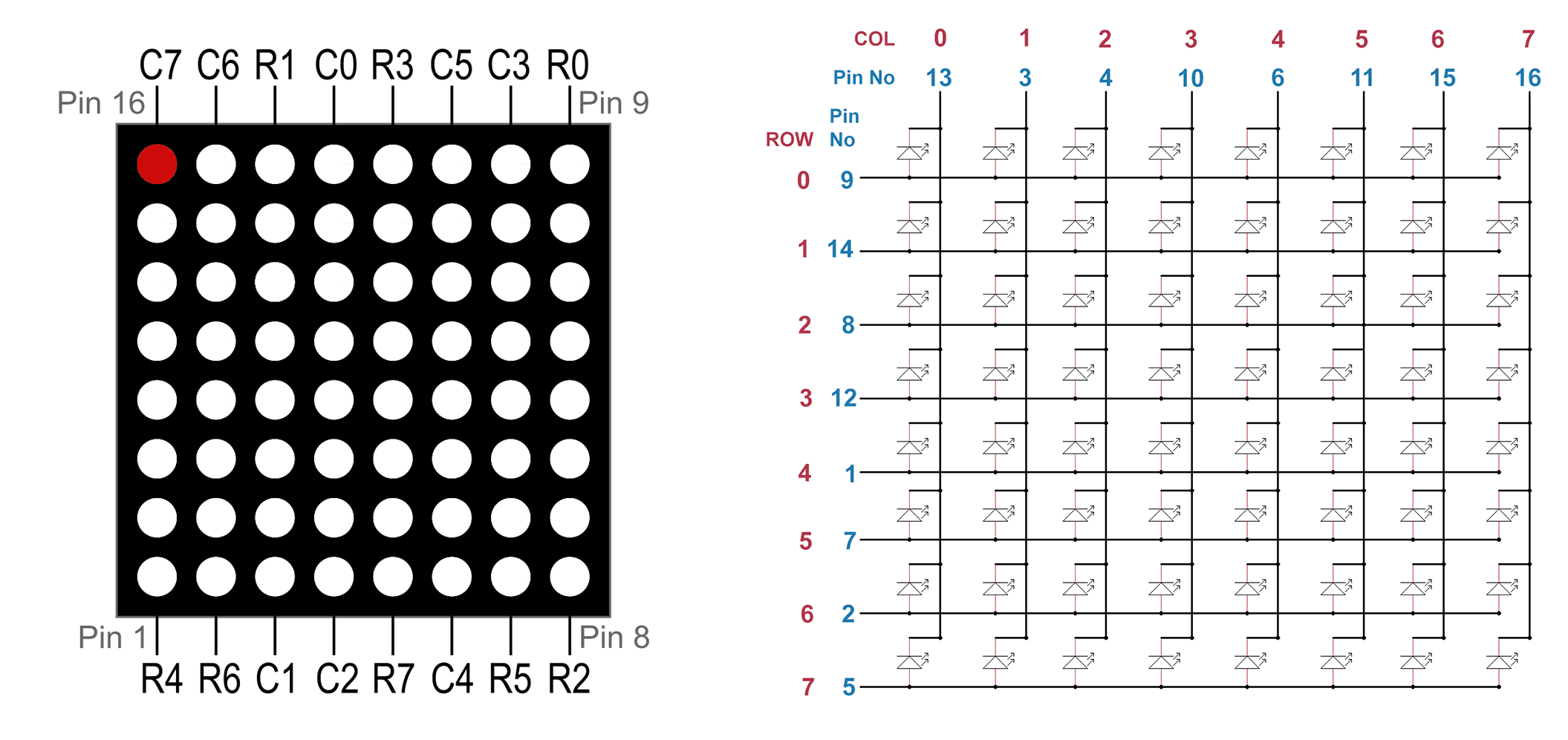
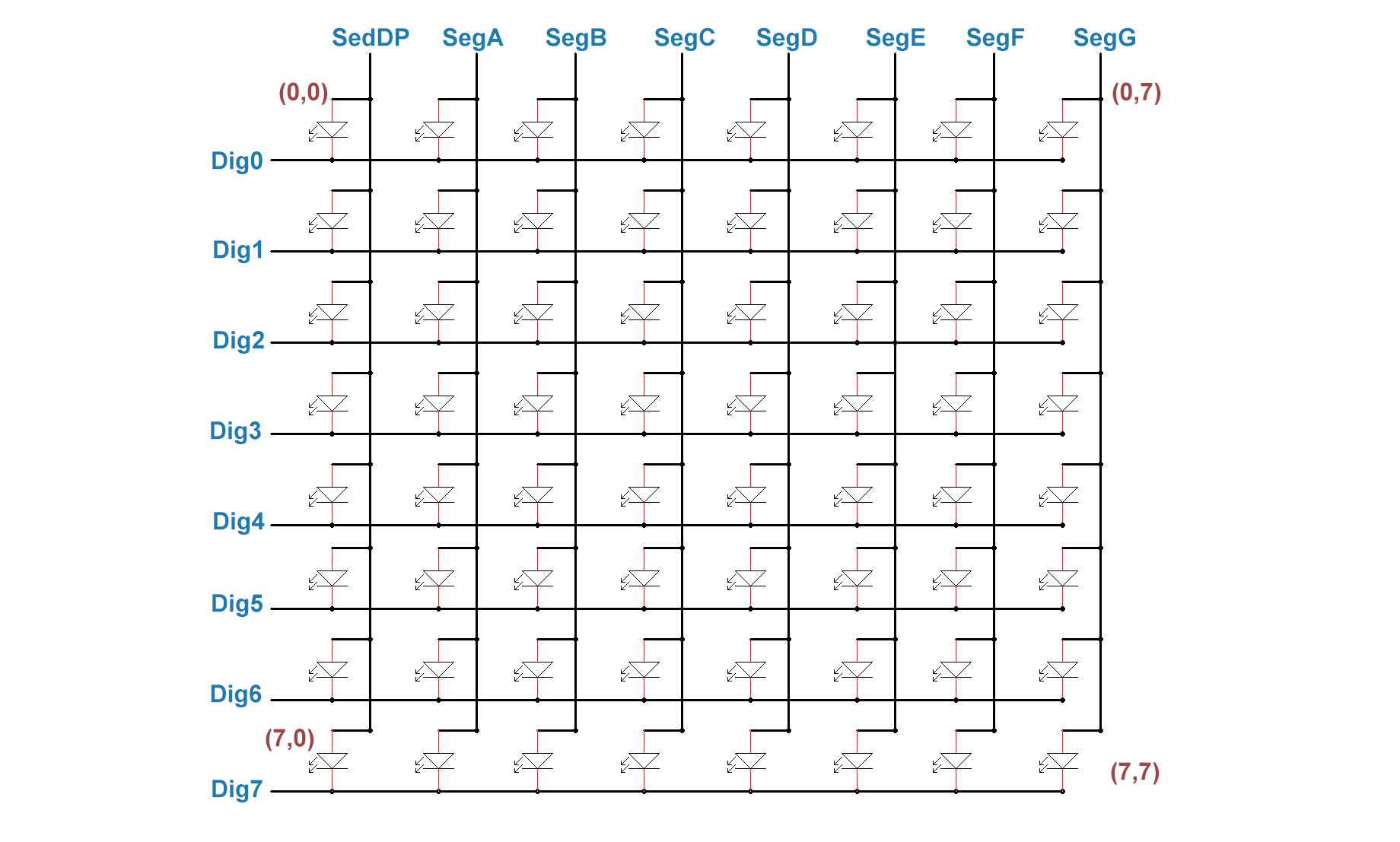
An LED dot matrix display is an LED array. Each input or output pin connects the LEDs of a row or a column. Whether the rows or the columns are the inputs or outputs varies from display to display.
By applying a voltage to an input pin and by connecting an output pin to ground, you can light up exactly one LED at the intersection of row and column.
If you don’t use a control IC like the MAX7219 or MAX7221, you’ll need to use series resistors. The resistance value required depends on the technical specifications of your display. Most of the time, however, 330 ohms will work with 5 volts.
Another note about the scheme above: usually in data sheets you will find a row and series numbering from 1 to 8. I recommend getting used to the numbering 0 to 7 from the beginning. Because then you think correctly in bits and bytes and that is helpful for the programming.
And one more thing: if I specify an LED position (a dot) in this article as a value pair (a/b), then a is the row and b is the column. I.e. it’s different from x and y in a coordinate system.
Where to get an LED dot matrix display
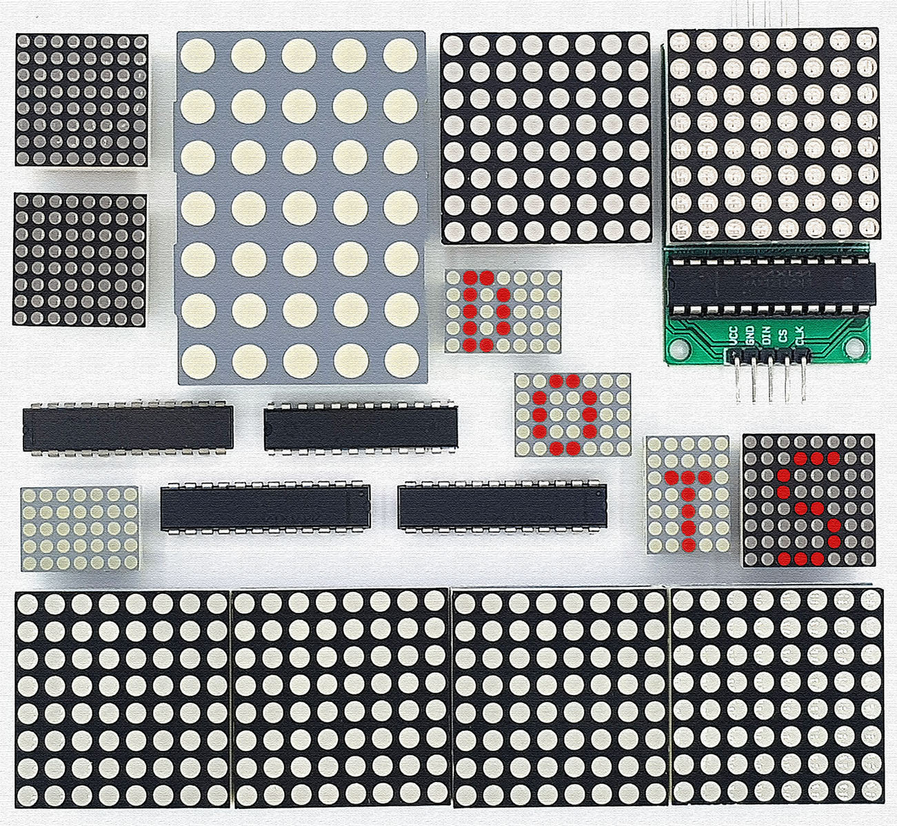
LED dot matrix displays are available in various versions. The number of LEDs (dots), the size of the displays and the color of the LEDs varies. In addition, they are available with integrated control IC and also as a combination of several single displays, e.g. 8 x 8 x 4. Search for “LED dot matrix display” or simply “dot matrix” in your favorite online store. Prices vary quite widely with origin and quantity.
Direct control via microcontroller or Arduino
I use as an example the 8×8 LED matrix display with row input and column output shown schematically above. First: the wiring is not fun, as eight inputs, eight outputs and eight resistors have to be connected. In addition, the rows and columns are assigned to the pins without an obvious system. You have to search quite a bit. Sometimes it is also not obvious which pin No 1. In this case, you have to try a little.
The whole first section serves more for didactics than for practice. Control ICs like the MAX7219 make life easier. And the displays with integrated control are even more convenient. I will come to that later. Nevertheless, one should first understand the principle.
Wiring
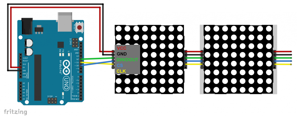
With 16 required inputs and outputs, the analog pins must also be included on the Arduino. Or you can use port expanders such as the MCP23017. This is what the circuit looks schematic and practical: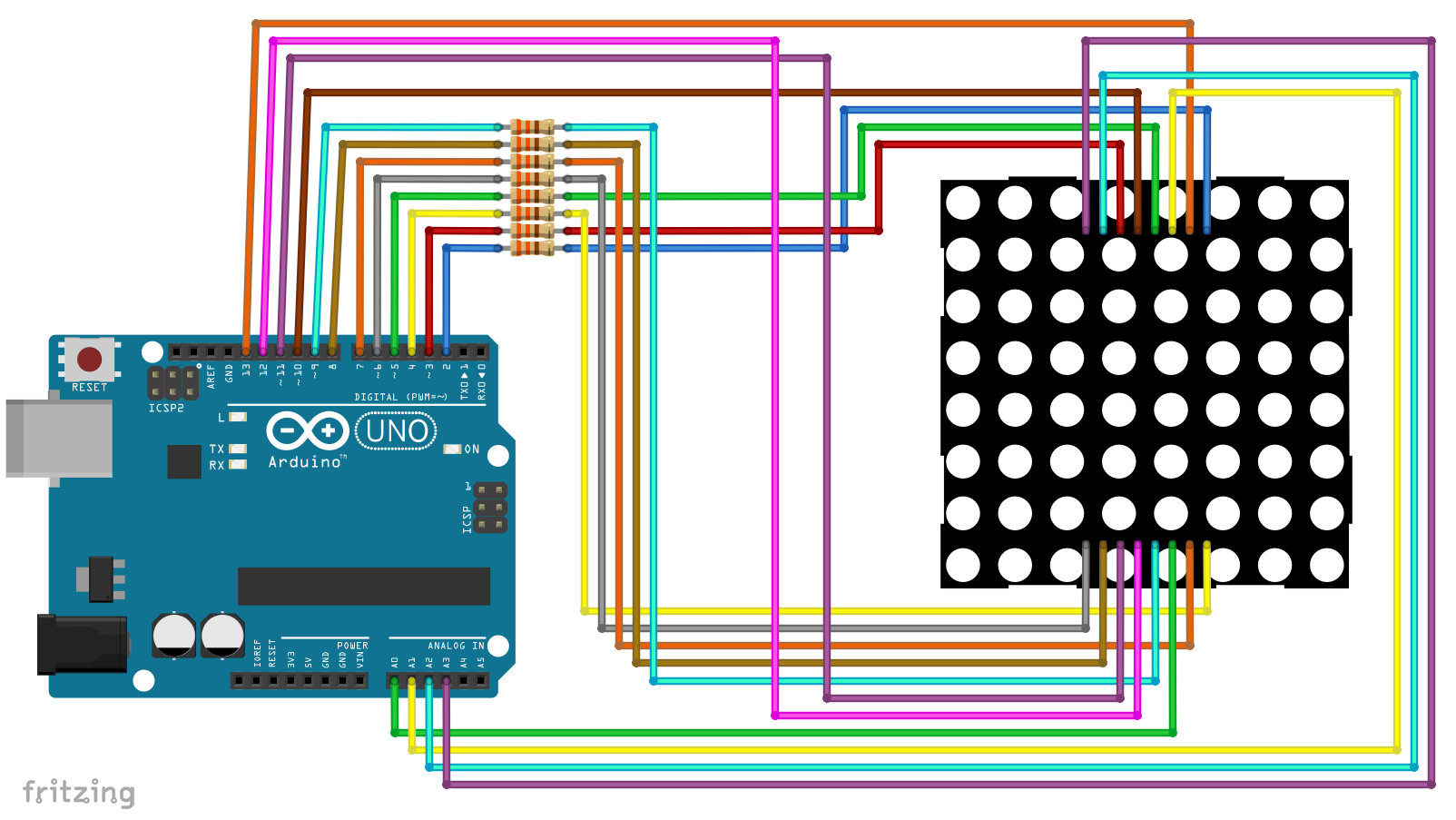

A small example sketch
The following example sketch first defines the Arduino pins for the rows and columns. The inputs (rows) are set to LOW, the outputs (columns) to HIGH. This means that all LEDs are off. An LED at the point “r/c” is switched on when the row “r” is set to HIGH and the column “c” is set to LOW.
As the first little play, there is a running light. One LED after the other shall light up briefly. After that the diagonal from (0/0) to (7/7) is switched on.
#define r0 2 // pin for row 0
#define r1 3 // pin for row 1
#define r2 4 // ...
#define r3 5
#define r4 6
#define r5 7
#define r6 8
#define r7 9
#define c0 10 // pin for column 0
#define c1 11 // pin for column 1
#define c2 12 // ...
#define c3 13
#define c4 A0
#define c5 A1
#define c6 A2
#define c7 A3

int row[] = {r0, r1, r2, r3, r4, r5, r6, r7};
int column[] = {c0, c1, c2, c3, c4, c5, c6, c7};

void setup() {
  for(int i = 0; i<=7; i++){
    pinMode(row[i], OUTPUT);
  }
  for(int i = 0; i<=7; i++){
    pinMode(column[i], OUTPUT);
  }
  clearDisplay();
}

void loop() {
  for(int i=0; i<=7; i++){
    for(int j=0; j<=7; j++){
      switchLED(row[i],column[j],1);
      delay(100);
      switchLED(row[i],column[j],0);
    }
  }
}

void clearDisplay(){
   for(int i = 0; i<=7; i++){
      digitalWrite(row[i],LOW);
  }
  for(int i = 0; i<=7; i++){
    digitalWrite(column[i], HIGH);
  }
}

void switchLED(int r, int c, bool ON){
  if(ON){
    digitalWrite(r, HIGH);
    digitalWrite(c, LOW);
  }
  else{
    digitalWrite(r, LOW);
    digitalWrite(c, HIGH);
  }
}
Unwanted cross-influence
Replace the main loop of the last sketch with the following:
void loop() {
  switchLED(row[0],column[0],1);
  delay(1000);
  switchLED(row[0],column[1],1);
  delay(1000);
  switchLED(row[1],column[0],1);
  delay(1000);
  clearDisplay();
}
Actually, the sketch should turn on the dots (0/0), (0/1) and (1/0). It does, but the with dot (1/0) also dot (1/1) is switched on. If you don’t know why, take a look at the 8×8 display scheme again. Then the problem should be obvious.
The solution: multiplexing
Now replace the main loop with the following:
void loop() {
  switchLED(row[0],column[0],1);
  delay(1);
  switchLED(row[0],column[0],0);
  switchLED(row[0],column[1],1);
  delay(1);
  switchLED(row[0],column[1],0);
  switchLED(row[1],column[0],1);
  delay(1);
  switchLED(row[1],column[0],0);
}
In this case, only the dots (0/0), (0/1) and (1/0) actually light up, as each dot is switched on separately for a short time. You don’t see flickering because the change is too fast.
The limits of simple multiplexing
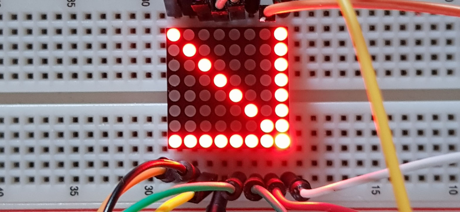
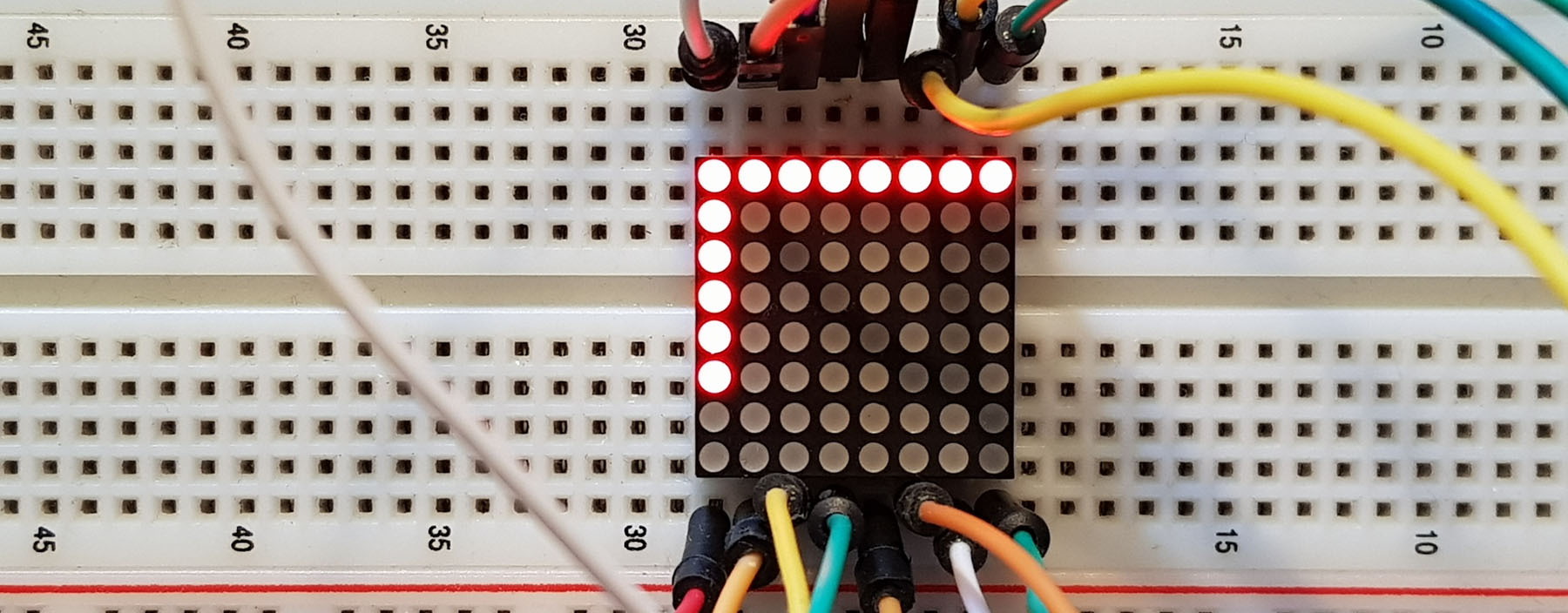
Increasing the multiplexing in this way leads to a decrease in intensity. In the following example, the dot (7,7) is always turned on, whereas the rest of the diagonal is multiplexed. The fact that the rest of the row and column 7 also light up is gain a side effect.
Note: Sketch lines 1 and 2 belong to the setup (I did not want to display the complete sketch again).
  switchLED(row[7],column[7], 1);
}

void loop() {
  for(int i=0; i<=6; i++){
    switchLED(row[i],column[i],1);
    delay(1);
    switchLED(row[i],column[i],0);
  }
}
In the photo you don’t see the differences as well as in reality. LEDs are not easy to photograph. Nevertheless, you may be able to see that the dot (7,7) is brighter.
There is also a solution to this problem. Pulse width modulation (PWM, see my article about timer) allows the intensity to be weighted depending on the number of “multiplexed” LEDs. However, I do not go into this in more detail now and would like to present the more convenient and common solution.
Control with the MAX7219 / MAX7221
All the above problems can be solved with the MAX7219 or MAX7221 control ICs. Since both are almost identical, I now only mention the MAX7219, but everything is applicable to both.
The MAX7219 is primarily designed for the control of 7-segment displays. It can also be used to drive LED dot matrix displays or loose LED arrays. This is not surprising, since controlling multiple 7-segment displays is basically a similar challenge as controlling an LED matrix display.
Pinout and technical features of the MAX7219
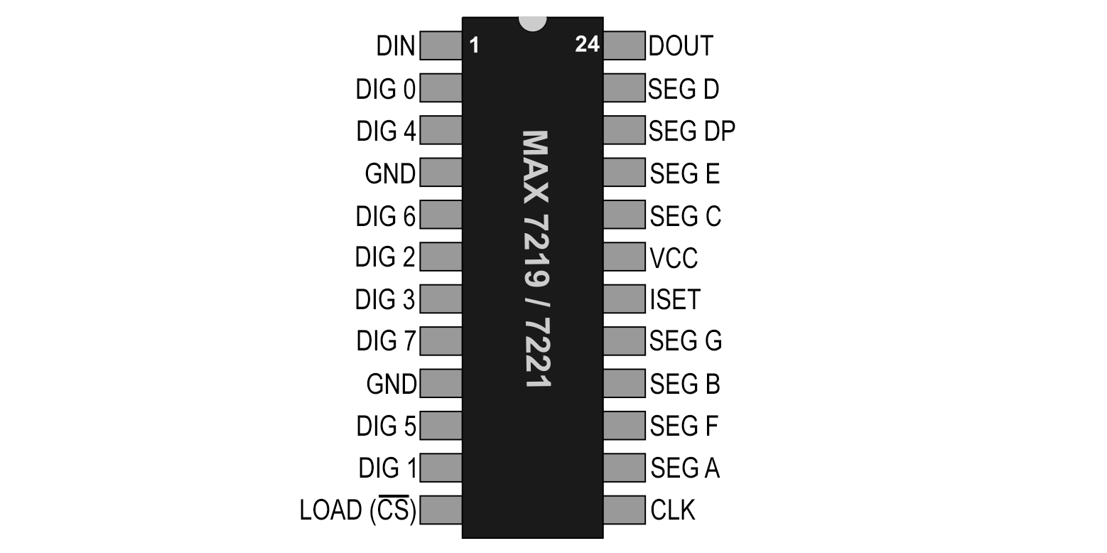
The MAX7219 has 24 pins:
- The SEG X pins provide the positive power supply
- Whether they are connected to the row or column pins depends on how the LEDs are installed in the display.
- The PINs DIG X switch to GND.
- The MAX7219 is controlled by SPI:
- DIN is the data input, i.e. MOSI (Master Out, Slave In).
- There is no MISO (Master In, Slave Out); so it’s a one-way communication.
- CLK: Clock Pin.
- LOAD / CS: Chip Select Pin.
- If you use multiple displays, DOUT is connected to DIN of the next display.
- 4 to 5.5 volts may be used on VCC
- On ISET, you set the current for the LEDs is set. I used 10 kOhm. In the data sheet of the MAX7219 you find a graph (page 4) which shows the impact of the resistance value and the voltage on the current.
Using the LedControl Library
To control the MAX7219, I use the LedControl library from Eberhard Fahle, which you can install from Github or directly via the library manager of the Arduino IDE. A good introduction can be found here.
The library actually expects the voltage input at the columns and the voltage output at the rows. That’s the other way around with the model I’m using. You can simply wire the other way around (Segx to the row pins, Digx to the column pins), but then you still have to rethink later.
The MAX7219 does not have many registers. That’s why it can be controlled without too much effort without a library. I will show you how to do this at the end of this article.
As far as the complexity of the wiring of the LED dot matrix display is concerned, the MAX7219 does not bring much advantage yet, but at least you don’t need the resistors:

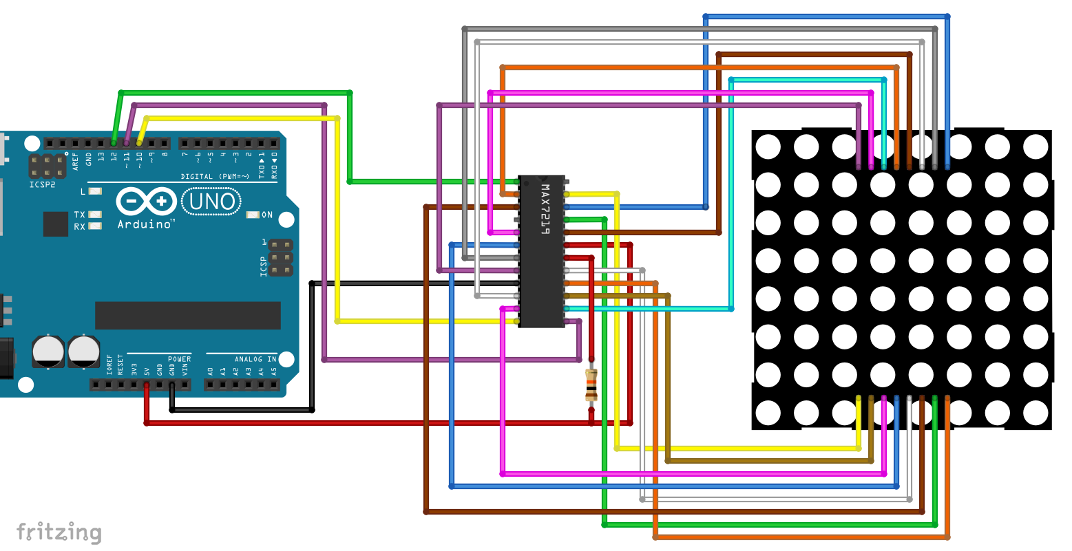
Note that the wiring shown above is specific to the LED dot matrix display I use. Maybe the connections of your display are the same, but maybe they aren’t.
A small example sketch
#include <LedControl.h>
//12= data pin(DIn), 11= CLK Pin, 10= Load/CS Pin, 1 = num of devices
LedControl lc88=LedControl(12,11,10,1);

void setup(){
  lc88.shutdown(0,false); // Wake up! 0= index of first device;
  lc88.setIntensity(0,2);
  lc88.clearDisplay(0);
  delay(500);
}

void loop(){
  for(int row=0; row<=7; row++){
    lc88.setLed(0,row,0,true);
    delay(250);
  }
  for(int col=0; col<=7; col++){
    lc88.setLed(0,0,col,true);
    delay(250);
  }
  delay(500);
  lc88.clearDisplay(0);
  delay(2000);
}
This example should showcase how to use most of the library’s features:
- first a display object is created and the connection pins and the number of individual displays are determined
shutdown(display, false)awakens the display; true sends it to sleep.setIntensity(display, value)sets the brightness of the dots to 0 < = value < 16clearDisplay(display)turns off all dots of a displaysetLed(display, row, col, true/false)turns on/off exactly one dot in a certain row and column.
Other useful features that you can try out yourself are:
setRow(display, row, val)– controls a complete row with one byte (val), e.g. 0b11110000 – > the first four LEDs are on, the last four are offsetColumn(display, col, val)– like setRow, but for setting columns- this function is considerably slower than the setRow function because it uses internally the setLed function (eight times per setColumn).
Since I had to swap the SEG and the DIG connection of my LED dot matrix display, rows and columns are also swapped. Actually, the sketch should fill column 0 first and then row 0. Obviously, it’s the other way around:
On the picture above you can see that the upper row is already completely lit and now the left column is completed.
The pragmatic solution is to simply rotate the display 90° counterclockwise. Then the dot (0/0) is at the bottom left (as in a coordinate cross) and not at the top left. You then have to rethink the line numbering.
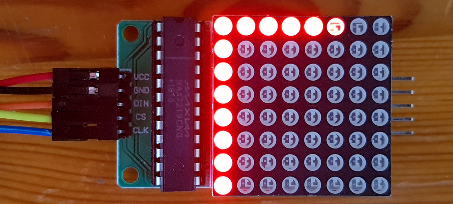
Using displays with built-in MAX7219
8x8x1 LED Matrix Display
If you want it the convenient way, I recommend using displays with integrated MAX7219. The wiring of such devices look much more pleasant:
It can be surprising where you find the origin (0/0). Just try it. This LED dot matrix display works as expected:
Note: if you switch on all LEDs of an 8×8 matrix display simultaneously, the power consumption can be several 100 mA per display. If you use multiple displays, you can easily exceed the limit of the Arduino. You should not try to use more than 500 mA from an Arduino UNO. If necessary, attach a separate power supply.
8x8x4 LED Matrix Display
If you want to use several displays sequentially, you might be eligible for a composite display. Above all, 8x8x4 displays are widely used. Again, you may be surprised where the dot (0/0) is located. To test, I used the following short sketch:
#include "LedControl.h"
LedControl lc884=LedControl(12,11,10,4);

unsigned long delaytime=3000;

void setup() {
  for(int i=0;i<4;i++){
    lc884.shutdown(i,false);
    lc884.setIntensity(i,8);
    lc884.clearDisplay(i);
  }
}

void loop() {
  lc884.setRow(0,0,B01111111);
  lc884.setRow(1,1,B00111111);
  lc884.setRow(2,2,B00011111);
  lc884.setRow(3,3,B00001111);
}
Actually, I would like the display 0 on the left and the display 4 on the right. I would also like to have the origin (0/0) at the top left and the rows should correspond to the order of the bits. That is, a 0b00001111 should make four dots of a row glow on the right and not on the left. I tested two displays from different sources and both did not fulfill all wishes. I was most likely to live with a reverse display order:

Display 0 is on the right side, but the rest is the way I want it to be. I use this arrangement below for the development of the ticker. If your display shows things differently, then you need to adjust the sketches accordingly (sorry!).
Programming of a ticker
Preparation: Creating and displaying letters
Letters, numbers, and characters are quickly designed on a sheet of checkered paper. Then you write the result line by line byte wise in arrays. In the following sketch you can see examples of A,r,d,u,i,n and o. I designed the letters quite narrow because I wanted to squeeze them later, so that the whole word “Arduino” fits on the display.
The letters are first displayed one after the other on the display 0. Then we take the first step towards the ticker by letting the letters display wise pass from right to left. My reference display is the invisible, virtual display -1.
#include "LedControl.h"
LedControl lc884=LedControl(12,11,10,4);

unsigned long delayTime=500;

byte a[8]={B00000000,B01100000,B10010000,B10010000,B10010000,B11110000,B10010000,B10010000};
byte r[8]={B00000000,B00000000,B00000000,B10100000,B11010000,B10000000,B10000000,B10000000};
byte d[8]={B00000000,B00010000,B00010000,B00010000,B01110000,B10010000,B10010000,B01110000};
byte u[8]={B00000000,B00000000,B00000000,B10010000,B10010000,B10010000,B10010000,B01110000};
byte i[8]={B00000000,B00000000,B01000000,B00000000,B01000000,B01000000,B01000000,B01000000};
byte n[8]={B00000000,B00000000,B00000000,B10100000,B11010000,B10010000,B10010000,B10010000};
byte o[8]={B00000000,B00000000,B00000000,B01100000,B10010000,B10010000,B10010000,B01100000};

void setup() {
  for(int i=0;i<4;i++){
    lc884.shutdown(i,false);
    lc884.setIntensity(i,8);
    lc884.clearDisplay(i);
  }
}

void loop() {
  oneMatrix();
  fourMatrices();
  delay(1000);
}

void oneMatrix(){
  displayCharAndWait(a,0);
  displayCharAndWait(r,0);
  displayCharAndWait(d,0);
  displayCharAndWait(u,0);
  displayCharAndWait(i,0);
  displayCharAndWait(n,0);
  displayCharAndWait(o,0);
}

void displayCharAndWait(byte* x, byte displayNumber){
  lc884.clearDisplay(displayNumber);
  for(int j=0; j<=7;j++){
    lc884.setRow(displayNumber,j,x[j]);
  }
  delay(delayTime);
  lc884.clearDisplay(displayNumber);
}


void fourMatrices(){
  for(int j=0; j<=10; j++){
    int currentMatrix = -1;
    if( ((currentMatrix+j)>=0) && ((currentMatrix+j)<4) ){
      displayChar(a,currentMatrix+j);
    }
    currentMatrix--;
    if( ((currentMatrix+j)>=0) && ((currentMatrix+j)<4) ){
      displayChar(r,currentMatrix+j);
    }
    currentMatrix--;
    if( ((currentMatrix+j)>=0) && ((currentMatrix+j)<4) ){
      displayChar(d,currentMatrix+j);
    }
    currentMatrix--;
    if( ((currentMatrix+j)>=0) && ((currentMatrix+j)<4) ){
      displayChar(u,currentMatrix+j);
    }
    currentMatrix--;
    if( ((currentMatrix+j)>=0) && ((currentMatrix+j)<4) ){
      displayChar(i,currentMatrix+j);
    }
    currentMatrix--;
    if( ((currentMatrix+j)>=0) && ((currentMatrix+j)<4) ){
      displayChar(n,currentMatrix+j);
    }
    currentMatrix--;
    if( ((currentMatrix+j)>=0) && ((currentMatrix+j)<4) ){
      displayChar(o,currentMatrix+j);
    }

    delay(delayTime);
    for(int i=0; i<=4; i++){
      lc884.clearDisplay(i);
    }
  }
}

void displayChar(byte *x, int displayNumber){
  lc884.clearDisplay(displayNumber);
  for(int j=0; j<=7;j++){
    lc884.setRow(displayNumber,j,x[j]);
  }
}
You can see what the result looks like in the video at the beginning of the post. Here is a snippet:

An intermediate step: static display as an unsigned long array
Displaying every letter in an individual display was easy. But it’s not particularly chic either. Moving dot wise would be nicer. Admittedly, I’ve been harder than I thought. I’ll show you a few solutions. Sometimes I maybe think in a way which is more complex than needed – if you have simpler solutions, please tell me!
For my solution No. 1, this is an intermediate step. First, I combined the letters so that they fit on the 8x8x4 display. For this purpose, I have reduced the gaps to a minimum and combined all rows 0, 1, 2, …. 7 in an unsigned long value. Since an unsigned long variable has 32 bits, this corresponds to the width of the 4-set display. Later display, however, the values have to be split in bytes again to display the part on the four displays. This is done by the function displayBanner().
#include "LedControl.h"
LedControl lc884=LedControl(12,11,10,4);

long delayTime=500;

unsigned long banner[8]={0b00000000000000000000000000000000,
                         0b01100000000001000000000000000000,
                         0b10010000000001000000100000000000,
                         0b10010101000001010010001010001100,
                         0b10010110100111010010101101010010,
                         0b11110100001001010010101001010010,
                         0b10010100001001010010101001010010,
                         0b10010100000111001110101001001100};

void setup() {
  for(int i=0;i<4;i++){
    lc884.shutdown(i,false);
    lc884.setIntensity(i,8);
    lc884.clearDisplay(i);
  }
}

void loop() {
  displayBanner(); delay(500);
}

void displayBanner(){
  byte currentMatrix[8];
  for(int j=0; j<4; j++){
    for(int i=0; i<8; i++){
      currentMatrix[i] = (((banner[i])>>(j*8)) & 0b11111111);
    }
    displayMatrix(currentMatrix,j);
  }
}

void displayMatrix(byte *matrix, int matrixNumber){
  for(int i=0; i<=7;i++){
    lc884.setRow(matrixNumber,i,matrix[i]);
  }
}
Here’s what the result is:

Move the unsigned long array dot wise
The advantage the unsigned long array is that the dot wise shifting is much easier to program via binary operations than managing it with bytes. The lettering is gradually moved to the left and split between the individual displays. When you follow the sketch, don’t forget that the display is 0 on the right.
As a small feature, I have built in that the lettering stops briefly when it is completely on the display. It briefly becomes brighter, then darker again and then moves out of the display. You can see the result in the video at the beginning of the post.
#include "LedControl.h"
LedControl lc884=LedControl(12,11,10,4);

long delayTime=150;

unsigned long banner[8]={0b00000000000000000000000000000000,
                         0b01100000000001000000000000000000,
                         0b10010000000001000000100000000000,
                         0b10010101000001010010001010001100,
                         0b10010110100111010010101101010010,
                         0b11110100001001010010101001010010,
                         0b10010100001001010010101001010010,
                         0b10010100000111001110101001001100};

void setup() {
  for(int i=0;i<4;i++){
    lc884.shutdown(i,false);
    lc884.setIntensity(i,8);
    lc884.clearDisplay(i);
  }
}

void loop() {
  calcCurrentBanner(); delay(500);
}

void calcCurrentBanner(){
  unsigned long currentBanner[8];
  for(int i=32; i>=0; i--){
    for(int j=0; j<8; j++){
      currentBanner[j] = (banner[j])>>i;
    }
    displayBanner(currentBanner);
    delay(delayTime);
  }
  stopAndHighlight();
  for(int i=0; i<33; i++){
    for(int j=0; j<8; j++){
      currentBanner[j] = (banner[j])<<i;
    }
    displayBanner(currentBanner);
    delay(delayTime);
  }
}

void displayBanner(unsigned long *cb){
  byte currentMatrix[8];
  for(int j=0; j<4; j++){
    for(int i=0; i<8; i++){
      currentMatrix[i] = (((cb[i])>>(j*8)) & 0b11111111);
    }
    displayMatrix(currentMatrix,j);
  }
}

void displayMatrix(byte *matrix, int matrixNumber){
  for(int i=0; i<=7;i++){
    lc884.setRow(matrixNumber,i,matrix[i]);
  }
}

void stopAndHighlight(){
  for(int i=8; i<16; i++){
    for(int j=0;j<4;j++){
      lc884.setIntensity(j,i);
      delay(20);
    }
  }
  delay(1000);
  for(int i=15; i>=8; i--){
    for(int j=0;j<4;j++){
      lc884.setIntensity(j,i);
      delay(20);
    }
  }
}
Longer tickers
Your ticker might be longer therefore it does not necessarily fit on the display or in an unsigned long array. That’s also possible, just a little more complex. As an example, I take the “uncondensed” Arduino lettering, which spans seven individual displays. I split this into a two-dimensional unsigned long array “bannerPart[2][8]”. Of course, I’m wasting some memory space because I don’t use the array completely.
This time I automated the transfer of the individual letters into the bannerPart array. This is done in the setup in the first two for-loops. In calcCurrentBanner() there are three for-loops, which stand for three phases. In the first phase, the first section of the lettering is pushed in. During the second phase, the first part (bannerPart[0]) is moving out and the free areas are filled with the second banner part. In the third phase, the second part is pushed out of the display.
#include "LedControl.h"
LedControl lc884=LedControl(12,11,10,4);

long delayTime=150;
byte banner[7][8]={{B00000000,B01100000,B10010000,B10010000,B10010000,B11110000,B10010000,B10010000},
                   {B00000000,B00000000,B00000000,B10100000,B11010000,B10000000,B10000000,B10000000},
                   {B00000000,B00010000,B00010000,B00010000,B01110000,B10010000,B10010000,B01110000},
                   {B00000000,B00000000,B00000000,B10010000,B10010000,B10010000,B10010000,B01110000},
                   {B00000000,B00000000,B01000000,B00000000,B01000000,B01000000,B01000000,B01000000},
                   {B00000000,B00000000,B00000000,B10100000,B11010000,B10010000,B10010000,B10010000},
                   {B00000000,B00000000,B00000000,B01100000,B10010000,B10010000,B10010000,B01100000}};

unsigned long bannerPart[2][8];

void setup(){
  unsigned long b1, b2, b3;
  for(int i=0; i<8; i++){
    unsigned long b1, b2, b3;
    b1 = ((unsigned long)(banner[0][i]))<<24;
    b2 = ((unsigned long)(banner[1][i]))<<16;
    b3 = ((unsigned long)(banner[2][i]))<<8;
    bannerPart[0][i] = b1 + b2 + b3 + banner[3][i];
  }
   for(int i=0; i<8; i++){
    unsigned long b1, b2, b3;
    b1 = ((unsigned long)(banner[4][i]))<<24;
    b2 = ((unsigned long)(banner[5][i]))<<16;
    b3 = ((unsigned long)(banner[6][i]))<<8;
    bannerPart[1][i] = b1 + b2 + b3;
  }

  for(int i=0;i<4;i++){
    lc884.shutdown(i,false);
    lc884.setIntensity(i,8);
    lc884.clearDisplay(i);
  }
}

void loop() {
  calcCurrentBanner();
  delay(500);
}

void calcCurrentBanner(){
  unsigned long currentBanner[8];
  for(int i=32; i>=0; i--){
    for(int j=0; j<8; j++){
      currentBanner[j] = (bannerPart[0][j])>>i;
    }
    displayBanner(currentBanner);
    delay(delayTime);
  }
  for(int i=1; i<=32; i++){
    for(int j=0; j<8; j++){
      currentBanner[j] = ((bannerPart[0][j])<<i) + ((bannerPart[1][j])>>(32-i));
    }
    displayBanner(currentBanner);
    delay(delayTime);
  }
  for(int i=1; i<=24; i++){
    for(int j=0; j<8; j++){
      currentBanner[j] = (bannerPart[1][j])<<i;
    }
    displayBanner(currentBanner);
    delay(delayTime);
  }
}

void displayBanner(unsigned long *cb){
  byte currentMatrix[8];
  for(int j=0; j<4; j++){
    for(int i=0; i<8; i++){
      currentMatrix[i] = (((cb[i])>>(j*8)) & 0b11111111);
    }
    displayMatrix(currentMatrix,j);
  }
}

void displayMatrix(byte *matrix, int matrixNumber){
  for(int i=0; i<=7;i++){
    lc884.setRow(matrixNumber,i,matrix[i]);
  }
}
The result can be found again in the video.
If you create your own tickers with a different width, you’ll need to adjust some values in the sketch. Admittedly, I was not motivated anymore to program the sketch in a more general way.
Other methods
Making a ticker using byte arrays is a bit more complicated than you might think at first. At least I struggled a little. You will find the sketch at the end of the post.
By far the simplest method would be a bool array, in which each dot is a separate variable. In this array you could also integrate the four virtual empty displays at the beginning and the four vitual empty displays at the end. This would be 4 + 7 (for the Arduino banner) + 4 = 15 single displays. This would result in a 120 x 8 array with 960 bool values. Moving it would be so easy to program. But unfortunately, each bool variable requires a cmplete byte of memory. This waste of storage space would go too far.
LED dot matrix display control without MAX7219 Library
As already mentioned, the MAX7219 does not have too many registers and can therefore be controlled easily without a library. In the next sketch you can see how this works.
But I don’t want to explain the sketch in detail either because this article is already quite long. If you put the data sheet next to it, it shouldn’t be so hard to understand. If you still have questions, ask! Just a few comments:
- The sketch uses the standard SPI ports for MOSI and CLK (for UNO pin 11 and 13, respectively). So, you have to rewire a little.
- MISO does not exist, the MAX7219 is not talkative.
- And because there is no MISO, the state of the dots cannot be queried.
- As you only want to change individual dots with the setLed function, but can only write whole series of bytes, the sketch has to keep records. This is done via the array “dots”.
#include <SPI.h>

const int slaveSelectPin = 10;
const int totalDevs = 4;
const int colsPerDev = 8;
const int rowsPerDev = 8;
byte dots[totalDevs][rowsPerDev] = {0}; // in diesem Array wird der Zustand der Dots gespeichert

byte a[8]={B00000000,B01100000,B10010000,B10010000,B10010000,B11110000,B10010000,B10010000};

void setup(){
  SPI.begin();
  pinMode(slaveSelectPin, OUTPUT);
  digitalWrite(slaveSelectPin, HIGH);
  for(int device=0; device<totalDevs; device++){
    wakeUp(device);                  // Normal Operation (shutdown beenden)
    displayTest(device,500);
    writeRegister(device,0x09,0x00); // Decode: 00 = Einzeldots, kein decoding
    setIntensity(device, 6);
    writeRegister(device,0x0B,0x07); // alle Reihen werden angezeigt
    clearDevice(device);
  }
  delay(500);
}

void loop(){
  setRow(0,0,B11111000);
  delay(1000);
  setLED(0,0,5,0);
  delay(1000);
  setLED(0,0,7,0);
  delay(1000);
  displayChar(1, a);
}


void clearDevice(int device){
  for(int row=0; row<=rowsPerDev; row++){  //alles ausschalten
    writeRegister(device,byte(row),0x00);
  }
}

void setIntensity(int device, int intensity){
  writeRegister(device,0x0A,intensity);
}

void displayTest(int device, int testTime){
  writeRegister(device,0x0F,0x01); //Display Test ein
  delay(testTime);
  writeRegister(device,0x0F,0x00); //Display Test aus
}

void wakeUp(int device){
  writeRegister(device,0x0C,0x01);
}

void shutDown(int device){
  writeRegister(device,0x0C,0x00);
}

void setRow(int device, byte row, byte data){
  dots[device][row] = data;
  writeRegister(device, row+1, data);
}

void setLED(int device, byte row, byte col, bool on){
  byte reg = row;
  byte dataToSend;
  byte mask;
  if(on){
    mask = (1<<(col));
    dots[device][row] |= mask;
  }
  else{
    mask = ~(1<<(col));
    dots[device][row] &= mask;
  }
  dataToSend = dots[device][row];
  writeRegister(device, reg+1, dataToSend);
}

void displayChar(int device, byte *character){
  for(int i=0; i<=7; i++){
    dots[device][i] = character[i];
    writeRegister(device,i+1,character[i]);
  }
}


void writeRegister(int device, byte reg, byte data){
  digitalWrite(slaveSelectPin, LOW);
  for(int i=0; i<(totalDevs-device); i++){
    SPI.transfer(0x00);
    SPI.transfer(0x00);
  }
  SPI.transfer(reg);
  SPI.transfer(data);
  for(int i=0; i<device; i++){
    SPI.transfer(0x00);
    SPI.transfer(0x00);
  }
  digitalWrite(slaveSelectPin, HIGH);
}
Finally…
… the ticker sketch based on byte arrays. Here I used a virtual display as a thought model, which moves through the physical display from right to left (see diagram below). A bit like a filmstrip moving along the projector behind the lens.

I wrote the sketch in a way that allows you adjust it easily to other display sizes. I have run it on two consecutive 8x8x4 matrix displays (only the numberOfPhysicalDisplays had to be changed from four to eight):

The sketch is quite compact, but somewhat difficult to “digest”. I have tried to make it reasonably understandable through comments. Have fun understanding my logic!
#include "LedControl.h"

const unsigned int delayTime = 150;
const int numberOfCharacters = 7;   // = A,r,d,u,i,n,o
const int numberOfPhysicalDisplays = 4;  // 4 Matrix Displays
const int displayWidth = 8;  // 8x8 Format
const int displayHeight = 8;
int numberOfSteps;            // Anzahl Verschiebeschritte
int numberOfVirtualDisplays;  // Anzahl virtuelle Displays

LedControl lc884=LedControl(12,11,10,numberOfPhysicalDisplays);

byte banner[7][8]={{B00000000,B01100000,B10010000,B10010000,B10010000,B11110000,B10010000,B10010000},
                   {B00000000,B00000000,B00000000,B10100000,B11010000,B10000000,B10000000,B10000000},
                   {B00000000,B00010000,B00010000,B00010000,B01110000,B10010000,B10010000,B01110000},
                   {B00000000,B00000000,B00000000,B10010000,B10010000,B10010000,B10010000,B01110000},
                   {B00000000,B00000000,B01000000,B00000000,B01000000,B01000000,B01000000,B01000000},
                   {B00000000,B00000000,B00000000,B10100000,B11010000,B10010000,B10010000,B10010000},
                   {B00000000,B00000000,B00000000,B01100000,B10010000,B10010000,B10010000,B01100000}};

void setup(){
  numberOfVirtualDisplays = numberOfPhysicalDisplays + numberOfCharacters;  // das virtuelle Gesamtdisplay besteht aus 4 leeren Displays + Anzahl der Zeichen
  numberOfSteps = numberOfVirtualDisplays * displayWidth;
  for(int i=0;i<numberOfPhysicalDisplays; i++){
    lc884.shutdown(i,false);
    lc884.setIntensity(i,8);
    lc884.clearDisplay(i);
  }
}

void loop(){
  for(int i=0; i<= numberOfSteps; i++){
    calcVisibleBannerPart(i);
  }
}

void calcVisibleBannerPart(int step){
  int currentFirstVirtualDisplay = step/displayWidth; // Erstes virtuelles Display, dass auf dem physikalischen Display abgebildet wird
  int bitPosition = step % displayWidth; // Bit-Position, an der die virtuellen Displays auf zwei benachbarte physikalische Displays verteilt werden
  byte matrixToDisplay[8]; // abzubildende Matrix

  for(int currentPhysicalDisplay=0; currentPhysicalDisplay<numberOfPhysicalDisplays; currentPhysicalDisplay++){ // Gehe die physikalischen Displays durch

    if( (currentFirstVirtualDisplay + currentPhysicalDisplay) == (numberOfPhysicalDisplays - 1)){
      for(int i=0; i < displayHeight; i++){
         matrixToDisplay[i] = banner[0][i] >> (8 - bitPosition);
      }
      displayMatrix(matrixToDisplay,(numberOfPhysicalDisplays-1 - currentPhysicalDisplay));  // mein 0tes Display ist rechts!
    }


    if( ((currentFirstVirtualDisplay + currentPhysicalDisplay) > (numberOfPhysicalDisplays - 1)) && (currentFirstVirtualDisplay + currentPhysicalDisplay) < (numberOfCharacters + numberOfPhysicalDisplays - 1) ){
      for(int i=0; i < displayHeight; i++){
         matrixToDisplay[i] = (((banner[currentFirstVirtualDisplay + currentPhysicalDisplay - numberOfPhysicalDisplays][i]) << bitPosition) + ((banner[currentFirstVirtualDisplay + currentPhysicalDisplay - numberOfPhysicalDisplays+1][i]) >> (8- bitPosition))) ;
      }
      displayMatrix(matrixToDisplay,(numberOfPhysicalDisplays-1 - currentPhysicalDisplay));
    }


    if( (currentFirstVirtualDisplay + currentPhysicalDisplay) == (numberOfCharacters + numberOfPhysicalDisplays-1)){
      for(int i=0; i < displayHeight; i++){
         matrixToDisplay[i] = banner[numberOfCharacters-1][i] << bitPosition;
      }
      displayMatrix(matrixToDisplay,(numberOfPhysicalDisplays-1 - currentPhysicalDisplay));
    }
  }
  delay(delayTime);
}

void displayMatrix(byte *matrix, int matrixNumber){
  for(int i=0; i<=7;i++){
    lc884.setRow(matrixNumber,i,matrix[i]);
  }
}
Appendix: Controlling a bi-color TA6932 based matrix display
There are also bi-color displays with dots that can light up red or green. They are controlled by a TA6932 chip. A library with the same name is available here on GitHub, or you can install it via the Arduino library manager.
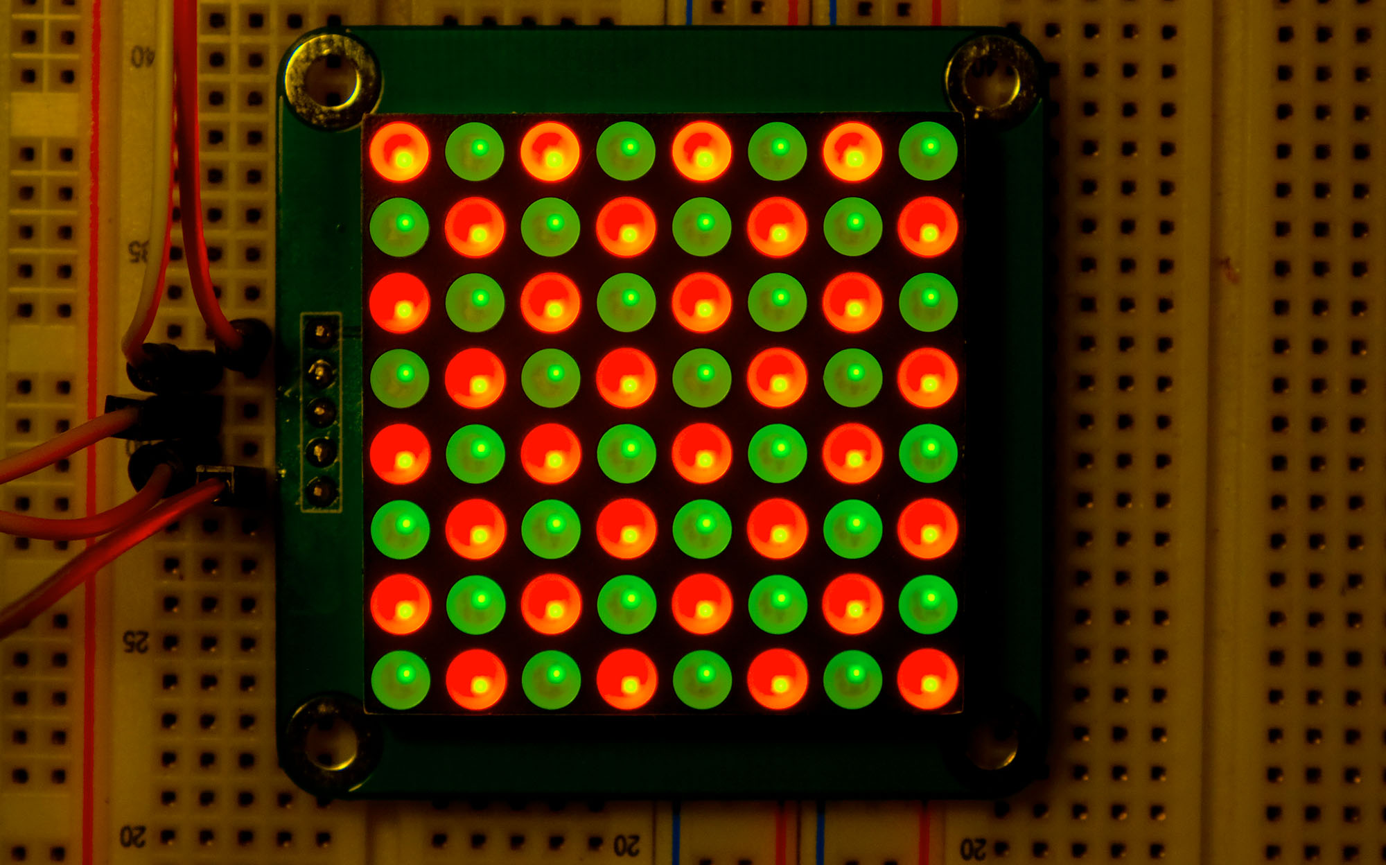
With the library, the control is simple. displayCache(row) = value defines which dots of a row are to be lit. The red dots are defined as rows 0 to 7. You address the green dots as rows 8 to 15. This should become clearer through the following sketch.
#include <TA6932.h>

#define PIN_TA6932_STB   8
#define PIN_TA6932_CLK   9
#define PIN_TA6932_DIN  10

TA6932 tm(PIN_TA6932_STB, PIN_TA6932_CLK, PIN_TA6932_DIN);

void setup() {
    tm.begin();

    tm.displayCache[0] = 0b00000001; // red dot at 0/0
    tm.updateDisplay();
    delay(2000);
    tm.displayCache[0] = 0b00000011; // red dots at 0/0 and 1/0
    tm.updateDisplay();
    delay(2000);
    tm.displayCache[0] = 0b00011011; // red dots at 0/0,1/0,3/0,4/0
    tm.updateDisplay();
    delay(2000);
    tm.displayCache[1] = 0b00000001; // red dot at 0/1;
    tm.updateDisplay();
    delay(2000);
    tm.displayCache[1] = 0b11110000; // red dots at 4/1,5/1,6/1,7/1
    tm.updateDisplay();
    delay(2000);
    tm.displayCache[3] = 0b11110000; // red dots at 4/3,5/3,6/3,7/3
    tm.updateDisplay();
    delay(2000);
    tm.displayCache[11] = 0b11110000; // green dots at 4/3,5/3,6/3,7/3 (in addition!)
    tm.updateDisplay();
    delay(2000);
    tm.displayCache[3] = 0b01010101; // red dots at 6/3,4/3,2/3,0/3
    tm.displayCache[11] = 0b10101010; // green dots at 7/3,5/3,3/3,1/3
    tm.updateDisplay();
    delay(2000);

    byte value = 0b10101010;
    for(int i=0; i<8; i++){
      tm.displayCache[i] = value;
      value = ~value; // inverts all bits
      tm.displayCache[i+8] = value;
    }
    tm.updateDisplay();
}

void loop() {
}
Hola Wolfgang, quiero hacer el siguiente Scrolling, que la Palabra HOLA, se vea como un desplazar de letras una por una, he agregado unas lineas para lograr hacerlo, pero no lgro que suceda, Hice la H, pero al agregar la O, la letra H, desaparece de la Matriz, puedes por favor decirme que debo agregar a el codigo me funcione, implemente tu codigo en Binario del Scrolling “Arduino” que hiciste pero no logro que me funcione, como una secuencia de letras y formar la palabra HOLA. Gracias
Hola Oswaldo, la pregunta es muy general. He presentado varias opciones para un banner en mi artículo. Cuál de mis ejemplos utilizó como base? También puedes enviarme tu programa (Wolfgang.Ewald@wolles-elektronikkiste.de) y le echaré un vistazo.
Saludos cordiales, Wolfgang
I just have a simple question, how can I send binary code from web to arduino using wifi and the arduino I’m using is ESP8266
Hi, I suggest you have a look at this post:
https://wolles-elektronikkiste.de/en/using-wifi-with-the-esp8266-and-esp32
Thank you very much, Wolfgang Ewald.
I have one more question
how can I String binary value in the unsigned long banner?
this is my sample
String value = “0b00000000000000000000000000000000,0b01100000000001000000000000000000,0b10010000000001000000100000000000,0b10010101000001010010001010001100,0b10010110100111010010101101010010,0b11110100001001010010101001010010,0b10010100001001010010101001010010,0b10010100000111001110101001001100”;
unsigned long banner[8]={value };
I can string the binary value inside the bracket.
I’m sorry for my questions because I’m just a beginner.
Hi Nelson, may I ask for which purpose you want to convert banner[8] into a string? If what you want to siplay on the dot matrix display is e.g. “Arduino” like I did in my article, then you know already that it is “Arduino”. The hard work is to convert the string or signs or whatever you want to display into an array – and this is manual work. Or have I understood your question wrongly?