About this Post
I had already dealt with the topic of WLAN or Wi-Fi many times, but rather casually, for example in my posts about the ESP32, the ESP8266, the Wemos boards, IFTTT and a few more. In this article, I would like to take a closer look at this exciting topic. Specifically, I will cover the following:
- Introduction / Basic Terms
- Setting up a web server
- Controlling a microcontroller via your Browser
- Connecting multiple microcontrollers via WLAN
- Appendix: If the refresh is disruptive
I explain the topic in detail and step by step so that it is also understandable for less experienced people. If this does not apply to you, you can certainly skip some paragraphs.
Update 14 December 2025: I have now also published an article about the Async WebServer (only for ESP32). Unlike the simple web server discussed here, this one does not block. You can find more information about the differences here.
Introduction / Basic Terms
Before I start, I would like to explain a few terms for a better understanding. Please forgive me if I simplify things to some extent.
WiFi vs WLAN
The term WiFi refers both to the company consortium Wi-Fi Alliance, which certifies WLAN devices, and to the associated WiFi 4, 5 and 6 brands. (source: Wikipedia). The abbreviation WiFi stands for “Wireless Fidelity”. WLAN, on the other hand, is the abbreviation for Wireless Local Area Network. In non-German-speaking countries, Wi-Fi is often used as a synonym for WLAN.
HTTP
The basis for communication on the World Wide Web is HTTP = Hypertext Transfer Protocol. This protocol determines how the devices networked on the WWW talk to each other. It is therefore also the basis for the communication via WLAN discussed here.
Client and Server
Communication via HTTP is based on the client-server principle. Simply put: The client asks, the server answers. This is comparable to the master-slave principle that you know from I2C and SPI.
host
“A host in IT can basically be any resource that can host another resource as a guest or provide the clients connected to it with certain IT services” (source: Frings Informatic). Each server is therefore a host, but not every host is a server.
HTML and CSS
HTML is the abbreviation for “Hypertext Markup Language”. It is the text-based, universal language of the WWW. CSS stands for “Cascading Style Sheets” and is based on HTML. CSS brings structure and object-orientation to HTML. You create templates (classes) that you can use again and again. The basics of HTML and CSS are easy to learn.
IP and router
The IP is the unique address of a device within a computer network according to the internetprotokoll. According to the IPv4 standard, the IP consists of 4 bytes, each separated by a period. Every device that is directly connected to the WWW has an individual IP, including your router. “Behind” the router is your home network with its own IPs. These are usually structured according to the scheme 192.168.x.y. A router is an interface between two networks.
Port
Ports are two-byte extensions of the network addresses that assign the transmitted data to specific applications. This makes it possible to distinguish whether a data packet is intended for the mail program or the web server (typically 80), for example. The port is appended to the IP, separated by a colon. E.g: 87.184.193.186:80.
Subnet mask
Your router assigns IPs that normally differ only in the last byte. For example, in my home network, the addresses are 192.168.178.x. If an address deviates from this scheme, then the router knows that it is outside the home network. This is expressed with the subnet mask. For my home network it is 255.255.255.0. In binary notation, the subnet mask is populated with ones from left to right. This part is fixed and can’t be changed. Only the part with the zeros can be freely used for the subnet addresses.
Gateway
A gateway is a device that connects two networks. In my home network, that’s the router. Its IP within my home network is 192.168.178.1.
DHCP
DHCP is the abbreviation for Dynamic Host Configuration Protocol. Your router operates a DHCP server that ensures that each device in your network (computer, smartphone, laptop, IP camera, etc.) is automatically assigned an IP.
Setting up a web server
I assume that you have already integrated your WiFi-enabled board into the Arduino IDE. There are so many instructions for this that I won’t go into it in detail.
We start simply by setting up a web server on the home network. I show this using the example of an ESP8266 (ESP8266-ESP01 or Wemos D1 Mini). For an ESP32 board, you only have to change two lines (see comments).
#include <ESP8266WebServer.h> // <WebServer.h> for ESP32
// #include <WiFi.h> // for ESP32
#define PORT 80

const char* ssid = "Your SSID";
const char* pass = "Your Password";

ESP8266WebServer server(PORT); // WebServer server(PORT); for ESP32

void setup(){
  Serial.begin(115200);
  Serial.print("Connecting to: ");
  Serial.println(ssid);
  WiFi.begin(ssid, pass);

  while(WiFi.status() != WL_CONNECTED){
    delay(500);
    Serial.print(".");
  }
  Serial.println("");
  Serial.println("WiFi connected");
  Serial.print("IP-Address of ESP8266 module: ");
  Serial.println(WiFi.localIP());

  server.begin();
}

void loop(){
}
Explanation of the sketch:
- You integrate ESP8266WebServer.h.
- The port for the web server is 80.
- “ssid” (service set Indentifier) and “pass” are the credentials for your home network.
ESP8266WebServer server(PORT);creates a web server object.WiFi.begin(ssid, pass)starts the WiFi connection.- You can find out the status of your connection with
WiFi.status(). WiFi.localIP()returns the IP that your router’s DHCP server has assigned to the ESP8266.server.begin()starts the WebServer, which does absolutely nothing in this sketch.
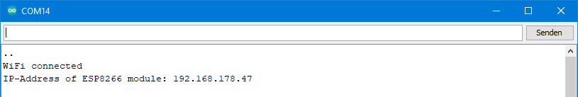
And that’s what it looks like in the serial monitor. My router has assigned the IP 192.168.178.47 to the ESP8266:
Set the IP yourself
With WiFi.config(), you can decide yourself which IP the ESP8266 should get – provided it is not already assigned to another device. To do this, modify the sketch as follows:
#include <ESP8266WebServer.h>  // <WebServer.h> for ESP32
// #include <WiFi.h> // for ESP32
#define PORT 80

const char* ssid = "Your SSID";
const char* pass = "Your Password";

IPAddress ip(192,168,178,110);
IPAddress gateway(192,168,178,1);
IPAddress subnet(255,255,255,0);

ESP8266WebServer server(PORT); // WebServer server(PORT) for ESP32

void setup(){
  Serial.begin(115200);
  Serial.print("Connecting to: ");
  Serial.println(ssid);
  WiFi.config(ip, gateway, subnet);
  WiFi.begin(ssid, pass);

  while(WiFi.status() != WL_CONNECTED){
    delay(500);
    Serial.print(".");
  }
  Serial.println("");
  Serial.println("WiFi connected");
  Serial.print("IP-Address of ESP8266 module: ");
  Serial.println(WiFi.localIP());

  server.begin();
}

void loop(){
}
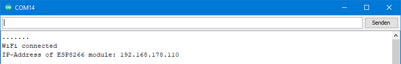
With most routers, it is possible to assign a fixed IP to the devices. In this way, you prevent the IP from being assigned elsewhere.
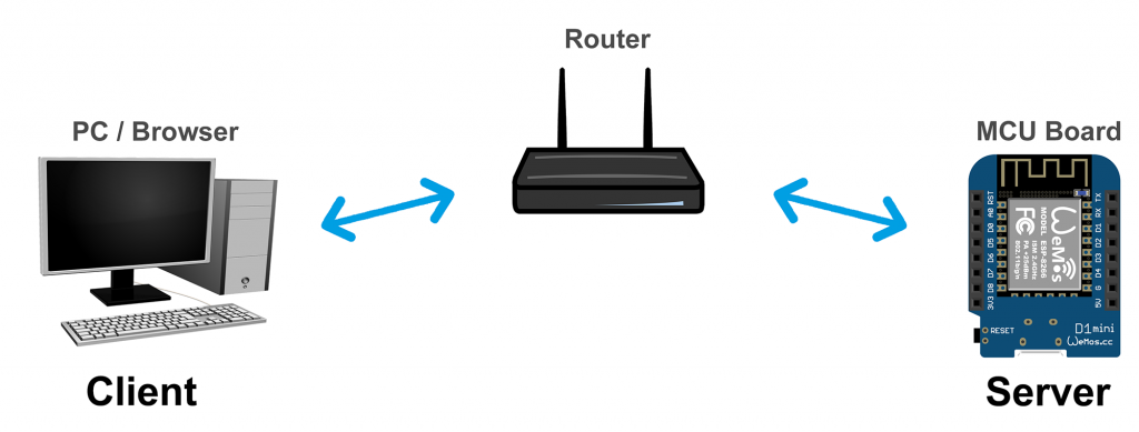
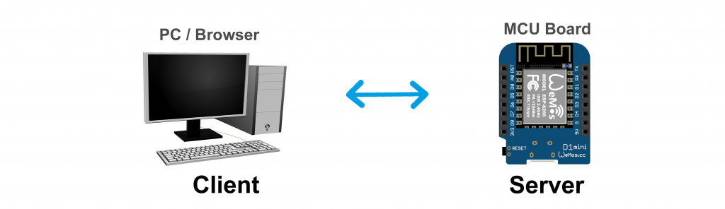
Controlling a Microcontroller via WiFi and Browser
In the following, I would like to show you how to control your ESP8266 or ESP32 board from a PC, laptop, smartphone, etc. via a browser. The specific task is the switching of three LEDs and the reading of a measured value. There’s more than one way to skin a cat, and this also applies here. I introduce two routes, the “server.on()-” and the “client-method”.
For the time being, the examples are implemented in the home network, i.e. communication takes place via the router:
The sketches are written for a Wemos D1 Mini board. If you use other boards, you still have to adjust them regarding the pins. If further adjustments are necessary for ESP32 boards, you will find corresponding comments.
The server.on() method
The term “server.on() method” is not a common term, especially since you might as well call your server object “yorkshire_pudding” instead of “server”. The same applies to the “client method”. I simply had to establish names to distinguish the methods, and I couldn’t think of anything better.
Switching one LED via browser
We start with something simple and switch only one LED. Connect the LED to a pin on your board. Take the following sketch and upload it to your board. Before, you may have to adjust it regarding the IP and the pin. Here is the sketch:
#include <ESP8266WebServer.h>  // <WebServer.h> for ESP32
// #include <WiFi.h> // for ESP32
#define LEDPIN D6  // choose an appropriate pin

const char* ssid = "Your SSID";
const char* pass = "Your Password";

IPAddress ip(192,168,178,110);
IPAddress gateway(192,168,178,1);
IPAddress subnet(255,255,255,0);

ESP8266WebServer server(80); // WebServer server(80); for ESP32

String led1= "<a href=\"/led_on\">LED On</a>";
String led0= "<a href=\"/led_off\">LED Off</a>";

void setup(){
  pinMode(LEDPIN, OUTPUT);
  digitalWrite(LEDPIN, LOW);
  Serial.begin(115200);
  Serial.println("Minimal Program to switch one LED");
  Serial.print("Connecting to: ");
  Serial.println(ssid);
  WiFi.config(ip, gateway, subnet);
  WiFi.begin(ssid, pass);

  while(WiFi.status() != WL_CONNECTED){
    delay(500);
    Serial.print(".");
  }
  Serial.println("");
  Serial.println("WiFi connected");
  Serial.print("IP-Address of ESP8266 module: ");
  Serial.println(WiFi.localIP());

  server.on("/",handleRoot);
  server.on("/led_on", ledon);
  server.on("/led_off", ledoff);
  server.begin();
}

void loop(){
  server.handleClient();
}

void handleRoot() {
  String message="<h1>Control your ESP8266 by your Browser</h1>";
  message += "Minimal version, just one LED</BR></BR>";
  message += led1;
  server.send(200, "text/html", message);
}

void ledon(){
  digitalWrite(LEDPIN, HIGH);
  server.send(200, "text/html", led0);
}

void ledoff(){
  digitalWrite(LEDPIN, LOW);
  server.send(200, "text/html", led1);
}
Now you go to the browser of a device that is connected to your home network. Type in the IP of your board, so in my case 192.168.178.110. Then it should look something like this:
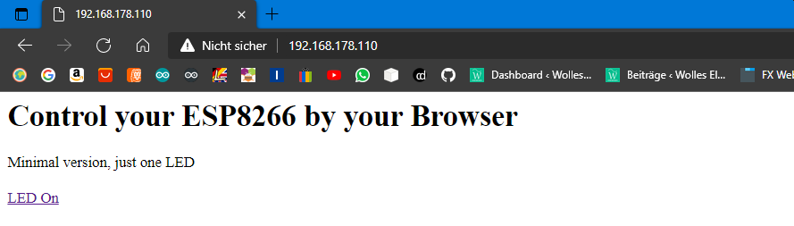
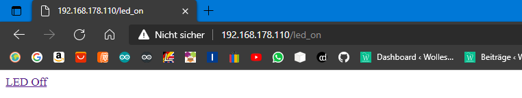
If you now click on the link “LED On”, the LED will be switched on and the link “LED Off” will appear on the screen. In addition, you can see that the address bar of the browser changes. In my case, to: 192.168.178.110/led_on. Now you can turn off the LED again.
Explanations to the sketch
I’ll start in the middle, namely in loop(). There you will only find the function server.handleClient(). It waits for requests from a client.
The call of 192.168.178.110 leads to the main path “/”. Strictly speaking, the browser sends a GET request. I’ll come back to that later.
The function server.on("/", handleRoot) was previously defined. It specifies that the handleRoot() function is executed when “/” is called. There, a string called “message” is defined, which is sent back to the browser using server.send(200, “text/html”, message). The “200” is an error code that tells the browser that everything is OK. You may know the error code “404 – page not found”.
“text/html” means that text and HTML code is sent. Everything between the characters less than and greater than is HTML. In most cases, HTML statements are valid for a specific area. <Statement> is the beginning of the area, </Anweisung> is the end. <h1> introduces the largest headline, </BR> causes a line break and with <a> a link begins. href is the link target. If you want to know more about HTML, you will find a very compact introduction here.
By clicking on the link “LED On”, the page 192.168.178.110/led_on is called. server.on("/led_on", ledon) determines that now the function ledon() is called. There, in turn, the LED is switched on, on the other hand, the link to page 192.168.178.110/led_off is sent to the browser and displayed there.
Of course, you can also turn on the LED by entering the IP including the path directly into the address bar of the browser like this: 192.168.178.110/led_on.
I hope that this has made the principle of this method clear.
Switching three LEDs and read a measured value
Now we will control three LEDs and read a measured value remotely. As an example of a measured value, we read out the voltage at an analog input.
You may have to adapt the following sketch to your board.
#include <ESP8266WebServer.h> // <WebServer.h> for ESP32
// #include <WiFi.h> // for ESP32

int led[3] = {D5,D6,D7}; // choose suitable pins
bool led_status[3] = {false};
const char* ssid = "Your SSID";
const char* pass = "Your Password";

IPAddress ip(192,168,178,110);
IPAddress gateway(192,168,178,1);
IPAddress subnet(255,255,255,0);

ESP8266WebServer server(80);  // WebServer server(80); for ESP32

String headAndTitle = "<head><meta http-equiv=\"refresh\" content=\"5\"></head>"
                      "<h1>Control your ESP8266 by Browser</h1>"
                      "Switch three LEDs and get a measured value, minimal version</BR></BR>";

String led0_1= "<a href=\"/led0_on\">LED0 On</a>";
String led0_0= "<a href=\"/led0_off\">LED0 Off</a>";
String led1_1= "</BR><a href=\"/led1_on\">LED1 On</a>";
String led1_0= "</BR><a href=\"/led1_off\">LED1 Off</a>";
String led2_1= "</BR><a href=\"/led2_on\">LED2 On</a>";
String led2_0= "</BR><a href=\"/led2_off\">LED2 Off</a>";

void setup(){
  pinMode(led[0], OUTPUT);
  digitalWrite(led[0], LOW);
  pinMode(led[1], OUTPUT);
  digitalWrite(led[1], LOW);
  pinMode(led[2], OUTPUT);
  digitalWrite(led[2], LOW);

  WiFi.config(ip, gateway, subnet);
  WiFi.begin(ssid, pass);

  server.on("/",handleRoot);
  server.on("/led0_on", led0on);
  server.on("/led0_off", led0off);
  server.on("/led1_on", led1on);
  server.on("/led1_off", led1off);
  server.on("/led2_on", led2on);
  server.on("/led2_off", led2off);
  server.begin();
}

void loop(){
  server.handleClient();
}

void handleRoot() {
  led0off();
}

void led0on(){
  led_status[0] = true;
  switchLEDAndSend(0,1);
}

void led0off(){
  led_status[0] = false;
  switchLEDAndSend(0,0);
}

void led1on(){
  led_status[1] = true;
  switchLEDAndSend(1,1);
}

void led1off(){
  led_status[1] = false;
  switchLEDAndSend(1,0);
}

void led2on(){
  led_status[2] = true;
  switchLEDAndSend(2,1);
}

void led2off(){
  led_status[2] = false;
  switchLEDAndSend(2,0);
}

void switchLEDAndSend(int num, bool state){
  String message = "";
  message += headAndTitle;

  digitalWrite(led[num], state);
  (led_status[0]==true)?(message += led0_0):(message += led0_1); // short version for if..then..else
  (led_status[1]==true)?(message += led1_0):(message += led1_1);
  (led_status[2]==true)?(message += led2_0):(message += led2_1);

  float measuredValue = analogRead(A0)/1024.0 * 3.3; // adjust to your board
  message += "</BR></BR>Voltage [V]: ";
  message += String(measuredValue, 2); // float to String, two decimal places
  server.send(200, "text/html", message);
}
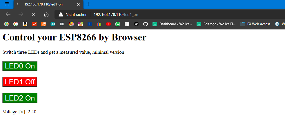
And this is what the result looks like in the browser:

Since we now turn three LEDs on and off, we need six server.on() functions plus another one for the main page. And we need to “remember” the status of the LEDs. For this I have defined the array “led_status”. Otherwise, the sketch doesn’t do anything new regarding the LEDs, it’s just longer.
What is new is that we read out a measured value here, convert it into a string and send it to the browser. You probably don’t want to keep revisiting the website to track changes in the reading. Line 14 ensures a regular update: <head><meta http-equiv=\"refresh\" content=\"5\"></head>. This causes the web page to reopen every 5 seconds.
Make it more beautiful with HTML and CSS
Our website is not yet visually appealing. Try replacing lines 19-24 with the following lines:
String led0_1= "<a href=\"/led0_on\"><button style=\"background: green; color: white; font-size: x-large; \">LED0 On</button></a>";
String led0_0= "<a href=\"/led0_off\"><button style=\"background: red; color: white; font-size: x-large; \">LED0 Off</button></a>";
String led1_1= "</BR></BR><a href=\"/led1_on\"><button style=\"background: green; color: white; font-size: x-large;\">LED1 On</button></a>";
String led1_0= "</BR></BR><a href=\"/led1_off\"><button style=\"background: red; color: white; font-size: x-large; \">LED1 Off</button></a>";
String led2_1= "</BR></BR><a href=\"/led2_on\"><button style=\"background: green; color: white; font-size: x-large; \">LED2 On</button></a>";
String led2_0= "</BR></BR><a href=\"/led2_off\"><button style=\"background: red; color: white; font-size: x-large; \">LED2 Off</button></a>";
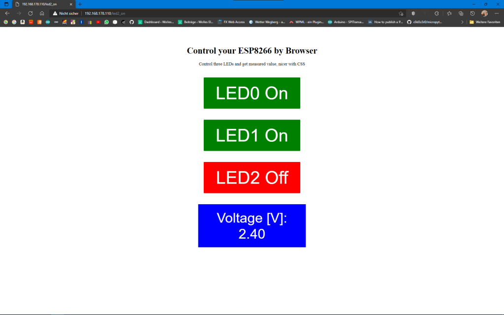
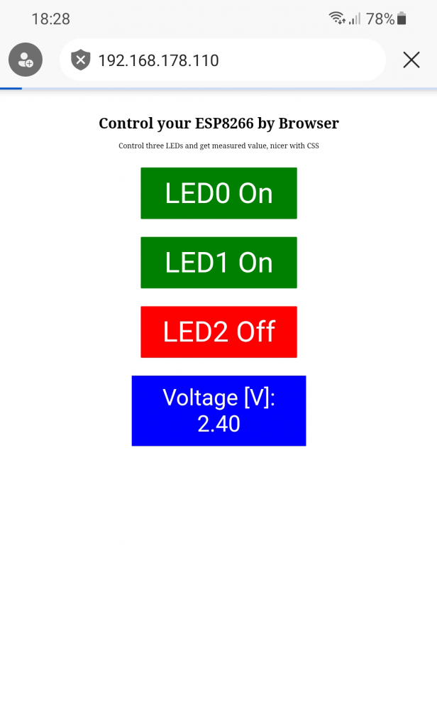
The result is a little nicer:
Or here again the whole sketch with CSS elements:
#include <ESP8266WebServer.h> // <WebServer.h> for ESP32
// #include <WiFi.h> // for ESP32

int led[3] = {D5,D6,D7};
bool led_status[3] = {false};
const char* ssid = "Your SSID";
const char* pass = "Your Password";

IPAddress ip(192,168,178,110);
IPAddress gateway(192,168,178,1);
IPAddress subnet(255,255,255,0);

ESP8266WebServer server(80);  // WebServer server(80); for ESP32

String headAndTitle = "<head><style>"
                        ".button {"
                          "border: none;"
                          "color: white;"
                          "width: 350px;"
                          "padding: 20px;"
                          "text-align: center;"
                          "margin: 20px 200px;"
                        "}"
                        ".greenButton {background-color: green; font-size: 64px;}"
                        ".greenButton:hover {background-color: darkgreen; font-size: 64px;}"
                        ".redButton {background-color: red; font-size: 64px;}"
                        ".redButton:hover {background-color: darkred; font-size: 64px;}"
                        ".blueBox {"
                          "background-color: blue;"
                          "color: white;"
                          "width: 350px;"
                          "padding: 20px;"
                          "text-align: center;"
                          "font-size: 50px;"
                          "font-family: arial;"
                          "margin: 20px 200px;"
                        "}"
                      "</style>"
                      "</head><meta http-equiv=\"refresh\" content=\"5\"></head>"
                      "</BR></BR><h1 align=\"center\">Control your ESP8266 by Browser</h1></div>"
                      "<div align=\"center\">Control three LEDs and get measured value, nicer with CSS</BR></BR></div>";

String led0_1= "<a href=\"/led0_on\"><button class=\"button greenButton\">LED0 On</button></a>";
String led0_0= "<a href=\"/led0_off\"><button class=\"button redButton\">LED0 Off</button></a>";
String led1_1= "</BR><a href=\"/led1_on\"><button class=\"button greenButton\">LED1 On</button></a>";
String led1_0= "</BR><a href=\"/led1_off\"><button class=\"button redButton\">LED1 Off</button></a>";
String led2_1= "</BR><a href=\"/led2_on\"><button class=\"button greenButton\">LED2 On</button></a>";
String led2_0= "</BR><a href=\"/led2_off\"><button class=\"button redButton\">LED2 Off</button></a>";

void setup(){
  pinMode(led[0], OUTPUT);
  digitalWrite(led[0], LOW);
  pinMode(led[1], OUTPUT);
  digitalWrite(led[1], LOW);
  pinMode(led[2], OUTPUT);
  digitalWrite(led[2], LOW);

  WiFi.config(ip, gateway, subnet);
  WiFi.begin(ssid, pass);

  server.on("/",handleRoot);
  server.on("/led0_on", led0on);
  server.on("/led0_off", led0off);
  server.on("/led1_on", led1on);
  server.on("/led1_off", led1off);
  server.on("/led2_on", led2on);
  server.on("/led2_off", led2off);
  server.begin();
}

void loop(){
  server.handleClient();
}

void handleRoot() {
  led0off();
}

void led0on(){
  led_status[0] = true;
  switchLEDAndSend(0,1);
}

void led0off(){
  led_status[0] = false;
  switchLEDAndSend(0,0);
}

void led1on(){
  led_status[1] = true;
  switchLEDAndSend(1,1);
}

void led1off(){
  led_status[1] = false;
  switchLEDAndSend(1,0);
}

void led2on(){
  led_status[2] = true;
  switchLEDAndSend(2,1);
}

void led2off(){
  led_status[2] = false;
  switchLEDAndSend(2,0);
}

void switchLEDAndSend(int num, bool state){
  String message = "";
  message += headAndTitle;
  message += "<div align=\"center\";>";

  digitalWrite(led[num], state);
  (led_status[0]==true)?(message += led0_0):(message += led0_1);
  (led_status[1]==true)?(message += led1_0):(message += led1_1);
  (led_status[2]==true)?(message += led2_0):(message += led2_1);

  float measuredValue = analogRead(A0)/1024.0 * 3.3;
  message += "</BR><div class=\"blueBox\">";
  message += "Voltage [V]: </BR>";
  message += String(measuredValue, 2);
  message += "</div>";
  message += "</div>";
  server.send(200, "text/html", message);
}
The presentation format is slightly larger and therefore suitable for use on a smartphone:
A deeper introduction to CSS would go beyond the scope of this article. A very brief introduction into CSS can be found here.
The client method
An alternative way to evaluate the client request server.on() is the client method. As already mentioned, this is not an official term. Here, a client object is created that reads client requests or sends messages to the client via read and print functions. This is similar to a Serial object.
#include "ESP8266WebServer.h" // use "WebServer.h" for ESP32
// #include <WiFi.h> // for ESP32
int led[3] = {D5,D6,D7}; // choose suitable pins
int analogPin = A0;
bool led_status[3] = {false};
const char* ssid = "Your SSID";
const char* password = "Your Password";
String headAndTitle = "<head><meta http-equiv=\"refresh\" content=\"5\"></head>"
"<h1>Control your ESP8266 by Browser</h1>"
"Control three LEDs and get measured value, client method</BR></BR>";
String led0_1= "<a href=\"/led0_on\"><button style=\"background: green; color: white; font-size: x-large; \">LED0 On</button></a>";
String led0_0= "<a href=\"/led0_off\"><button style=\"background: red; color: white; font-size: x-large; \">LED0 Off</button></a>";
String led1_1= "</BR></BR><a href=\"/led1_on\"><button style=\"background: green; color: white; font-size: x-large;\">LED1 On</button></a>";
String led1_0= "</BR></BR><a href=\"/led1_off\"><button style=\"background: red; color: white; font-size: x-large; \">LED1 Off</button></a>";
String led2_1= "</BR></BR><a href=\"/led2_on\"><button style=\"background: green; color: white; font-size: x-large; \">LED2 On</button></a>";
String led2_0= "</BR></BR><a href=\"/led2_off\"><button style=\"background: red; color: white; font-size: x-large; \">LED2 Off</button></a>";
IPAddress ip(192,168,178,110);
IPAddress gateway(192,168,178,1);
IPAddress subnet(255,255,255,0);
WiFiServer server(80);
WiFiClient client;
void setup() {
pinMode(led[0], OUTPUT);
digitalWrite(led[0], LOW);
pinMode(led[1], OUTPUT);
digitalWrite(led[1], LOW);
pinMode(led[2], OUTPUT);
digitalWrite(led[2], LOW);
Serial.begin(115200);
while(!Serial) {}
Serial.println();
Serial.print("Connecting to ");
Serial.println(ssid);
WiFi.config(ip, gateway, subnet);
WiFi.begin(ssid, password);
while(WiFi.status() != WL_CONNECTED){
delay(500);
Serial.print(".");
}
Serial.println("");
Serial.println("WiFi connected");
Serial.println("IP address: ");
Serial.println(WiFi.localIP());
server.begin();
}
void loop(){
client = server.available();
if(client){
Serial.println("New client");
boolean currentLineIsBlank = true;
String clientMessage = "";
while(client.connected()){
if(client.available()){
char c = client.read();
// Serial.write(c); //uncomment to print the request
if(clientMessage.length()<50){
clientMessage += c;
}
if(c == '\n' && currentLineIsBlank){
evaluateClientMessage(clientMessage);
break;
}
if(c == '\n'){
currentLineIsBlank = true;
}
else if(c != '\r'){
currentLineIsBlank = false;
}
}
}
delay(1);
client.stop();
Serial.println("client disconnected");
}
}
void evaluateClientMessage(String &msg){
if(msg.indexOf("led0_off") > 0){
led_status[0] = false;
}
else if(msg.indexOf("led0_on") > 0){
led_status[0] = true;
}
else if(msg.indexOf("led1_off") > 0){
led_status[1] = false;
}
else if(msg.indexOf("led1_on") > 0){
led_status[1] = true;
}
else if(msg.indexOf("led2_off") > 0){
led_status[2] = false;
}
else if(msg.indexOf("led2_on") > 0){
led_status[2] = true;
}
for(int i=0; i<3; i++){
digitalWrite(led[i], led_status[i]);
}
String ledString = "";
(led_status[0]==true)?(ledString += led0_0):(ledString += led0_1);
(led_status[1]==true)?(ledString += led1_0):(ledString += led1_1);
(led_status[2]==true)?(ledString += led2_0):(ledString += led2_1);
float measuredValue = analogRead(analogPin)/1024.0 * 3.3;
client.println("HTTP/1.1 200 OK");
client.println("Content-Type: text/html");
client.println("Connection: close");
client.println(); // this line is not redundant!
client.println(headAndTitle);
client.println(ledString);
client.println("</BR></BR></BR><span style=\"font-family: Arial; background: blue; color: white; font-size: x-large;\"> Voltage [V]: ");
client.println(String(measuredValue,2));
client.println(" </span>");
}
I’ll just go into the essential parts of the sketch. The loop() constantly checks whether the client sends a GET request. If this is the case, the GET request is read character by character with client.read() and combined into the string “clientMessage”. The GET request ends with a blank line (if(c == '\n' && currentLineIsBlank){...}). ‘\n’ is the escape sequence for a new line, ‘\r’ is the escape sequence for a carriage return. The crucial information is in the first part of the request, so we only include the first 50 characters.
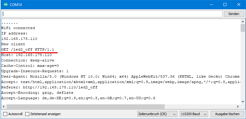
If you uncomment line 66, the complete request is shown on the serial monitor:
Now that we have stored the relevant part of the GET request in the string “clientMessage”, we search it for the keywords led0_on, led0_off, led1_on, etc. For this, we use the practical function indexOf(searchstring) that returns the position of the substring you are looking for. In case the substring you are looking for does not exist, indexOf() returns -1.
The rest is quite similar to the previous sketches. Only the information is not sent to the client with server.send(), but with client.println(). The result is the same.
Station (STA) and Access point (AP) WiFi modes
In the previous examples, the microcontroller board has connected to an existing WLAN. This is the so-called STA (“station”) mode. With minor changes, the microcontroller board itself can be turned into an access point (= hot spot). This is the AP mode that makes you independent of your router.
The following lines make the difference:
IPAddress ip(192,168,4,1);
IPAddress gateway(192,168,4,1);
IPAddress subnet(255,255,255,0);
....
....
WiFi.softAPConfig(ip, gateway, subnet);
Wifi.softAP(ssid, pass);
And here is the whole sketch:
#include <ESP8266WebServer.h>  // <WebServer.h> for ESP32
// #include <WiFi.h> // for ESP32

int led[3] = {D5,D6,D7};
bool led_status[3] = {false};
const char* ssid = "ESP8266_Server";  // choose a name
const char* pass = "blablablabla"; // must be >= 8 characters (at least for the ESP32)!

IPAddress ip(192,168,4,1); // should be 192.168.4.x
IPAddress gateway(192,168,4,1);  // should be 192.168.4.x
IPAddress subnet(255,255,255,0);

ESP8266WebServer server(80);  // WebServer server(80); for ESP32

String headAndTitle = "<head><style>"
                        ".button {"
                          "border: none;"
                          "color: white;"
                          "width: 350px;"
                          "padding: 20px;"
                          "text-align: center;"
                          "margin: 20px 200px;"
                        "}"
                        ".greenButton {background-color: green; font-size: 64px;}"
                        ".redButton {background-color: red; font-size: 64px;}"
                        ".blueButton {background-color: blue; font-size: 50px;}"
                      "</style>"
                      "</head><meta http-equiv=\"refresh\" content=\"5\"></head>"
                      "</BR></BR><h1 align=\"center\">Control your ESP8266 by Browser</h1></div>"
                      "<div align=\"center\">Control three LEDs and get measured value, AP - ModeS</BR></BR></div>";

String led0_1= "<a href=\"/led0_on\"><button class=\"button greenButton\">LED0 On</button></a>";
String led0_0= "<a href=\"/led0_off\"><button class=\"button redButton\">LED0 Off</button></a>";
String led1_1= "</BR><a href=\"/led1_on\"><button class=\"button greenButton\">LED1 On</button></a>";
String led1_0= "</BR><a href=\"/led1_off\"><button class=\"button redButton\">LED1 Off</button></a>";
String led2_1= "</BR><a href=\"/led2_on\"><button class=\"button greenButton\">LED2 On</button></a>";
String led2_0= "</BR><a href=\"/led2_off\"><button class=\"button redButton\">LED2 Off</button></a>";

void setup(){
  pinMode(led[0], OUTPUT);
  digitalWrite(led[0], LOW);
  pinMode(led[1], OUTPUT);
  digitalWrite(led[1], LOW);
  pinMode(led[2], OUTPUT);
  digitalWrite(led[2], LOW);

  WiFi.softAPConfig(ip, gateway, subnet);
  WiFi.softAP(ssid, pass);

  delay(500);

  server.on("/",handleRoot);
  server.on("/led0_on", led0on);
  server.on("/led0_off", led0off);
  server.on("/led1_on", led1on);
  server.on("/led1_off", led1off);
  server.on("/led2_on", led2on);
  server.on("/led2_off", led2off);
  server.begin();
}

void loop(){
  server.handleClient();
}

void handleRoot() {
  led0off();
}

void led0on(){
  led_status[0] = true;
  switchLEDAndSend(0,1);
}

void led0off(){
  led_status[0] = false;
  switchLEDAndSend(0,0);
}

void led1on(){
  led_status[1] = true;
  switchLEDAndSend(1,1);
}

void led1off(){
  led_status[1] = false;
  switchLEDAndSend(1,0);
}

void led2on(){
  led_status[2] = true;
  switchLEDAndSend(2,1);
}

void led2off(){
  led_status[2] = false;
  switchLEDAndSend(2,0);
}

void switchLEDAndSend(int num, bool state){
  String message = "";
  message += headAndTitle;
  message += "<div align=\"center\";>";

  digitalWrite(led[num], state);
  (led_status[0]==true)?(message += led0_0):(message += led0_1);
  (led_status[1]==true)?(message += led1_0):(message += led1_1);
  (led_status[2]==true)?(message += led2_0):(message += led2_1);

  float measuredValue = analogRead(A0)/1024.0 * 3.3; // adjust for your board
  message += "</BR><button class=\"button blueButton\">";
  message += "Voltage [V]: </BR>";
  message += String(measuredValue, 2);
  message += "</button>";
  message += "</div>";
  server.send(200, "text/html", message);
}
You have to connect to the WLAN of the MCU with your PC/laptop/smartphone/tablet and not to the network of your router. The appearance in the browser does not change.
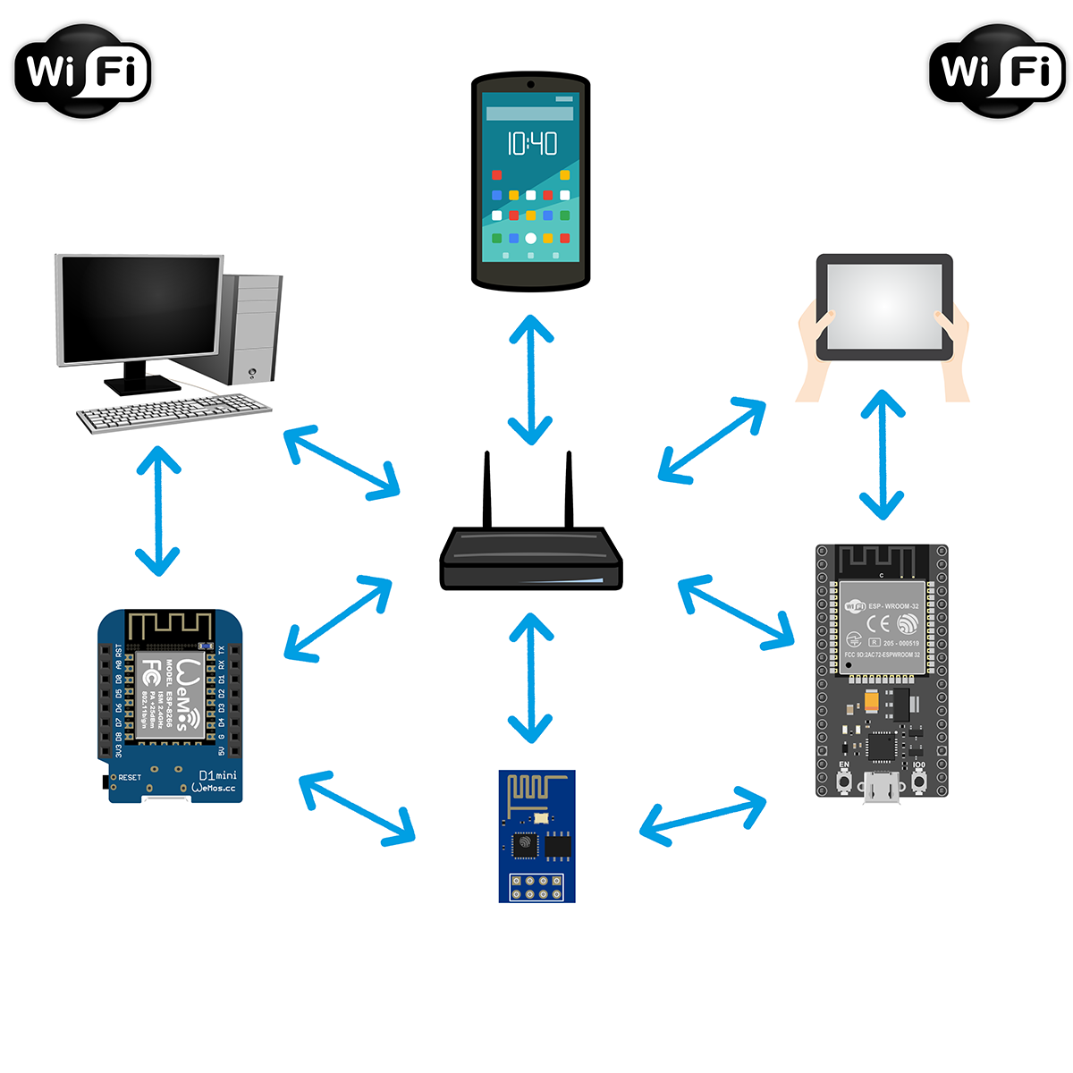
Connecting multiple microcontrollers via WLAN
Registering several microcontrollers (short: MCU for microcontroller unit) in a WLAN is easy. This section is more about how the MCUs involved can communicate with each other.
A typical application would be: You have several MCUs in use in your home that measure something (temperature, humidity, etc.). Then you probably don’t want to query each MCU individually, but collect the values on a server and output them on a single website.
Getting Started: Send a GET request to a Server
We implement the project by the “collecting” MCU (client) requesting the data from the other MCUs via GET requests. I will first show how this works in principle with the help of this simple set-up:
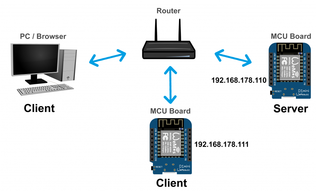
We are therefore adding another microcontroller as a client to the previous setup, which is connected to the WLAN via the router. This client MCU requests the server’s main page “/” via a GET request (just as the PC’s browser does when it calls up the page).
The server MCU runs the sketch ESP8266_ESP32_three_LEDs.ino. And here is the sketch for the client:
#include <ESP8266WiFi.h>  // use "WebServer.h" for ESP32
// #include <WiFi.h> // for ESP32

const char* ssid     = "Your SSID";
const char* password = "Your Password";
const char* host = "192.168.178.110";

IPAddress ip(192,168,178,111);
IPAddress gateway(192,168,178,1);
IPAddress subnet(255,255,255,0);

void setup() {
  Serial.begin(115200);
  delay(10);
  Serial.println();
  Serial.println();
  Serial.print("Connecting to ");
  Serial.println(ssid);

  WiFi.config(ip, gateway, subnet);
  WiFi.begin(ssid, password);

  while (WiFi.status() != WL_CONNECTED) {
    delay(500);
    Serial.print(".");
  }

  Serial.println("");
  Serial.println("WiFi connected");
  Serial.println("IP address: ");
  Serial.println(WiFi.localIP());
  Serial.println();
}

void loop() {
  Serial.print("connecting to ");
  Serial.println(host);
  WiFiClient client;
  const int httpPort = 80;
  if (!client.connect(host, httpPort)) {
    Serial.println("connection failed");
    return;
  }
  String url = "/";
  Serial.print("Requesting URL: ");
  Serial.println(url);

  client.print(String("GET ") + url + " HTTP/1.1\r\n" +
               "Host: " + host + "\r\n" +
               "Connection: close\r\n\r\n");
  unsigned long lasttime = millis();

  while (!client.available() && ((millis() - lasttime) < 3000)){
    delay(1);
  }
  while (client.available()) {
    String line = client.readStringUntil('\r');
    Serial.println(line);
  }
  Serial.println();
  Serial.println("closing connection");
  delay(60000);
}
The main points are:
- The client MCU connects to the WLAN network with the IP address 192.168.178.111.
- The client connects to the server (“host”):
client.connect(host, httpPort)
- Then the client sends a GET request.
- The client waits up to three seconds for an answer to come:
while (!client.available() && ((millis() - lasttime) < 3000)){- A waiting period is important because the host may be busy with another client (here: the PC).
- The host’s response is read line by line and output to the serial monitor:
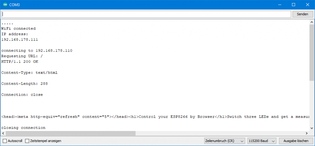
Now we could further evaluate the message and extract the analog reading. But we don’t do that, because this sketch is only meant to clarify the principle.
Connecting multiple MCUs with one MCU as access point
The task:
- Three microcontrollers measure voltages at analog inputs
- One of the microcontrollers serves as an access point, the other two run in STA mode.
- The two microcontrollers in STA mode send their measured values to the AP microcontroller, from where they can be output in the browser of a PC, smartphone, tablet, etc.
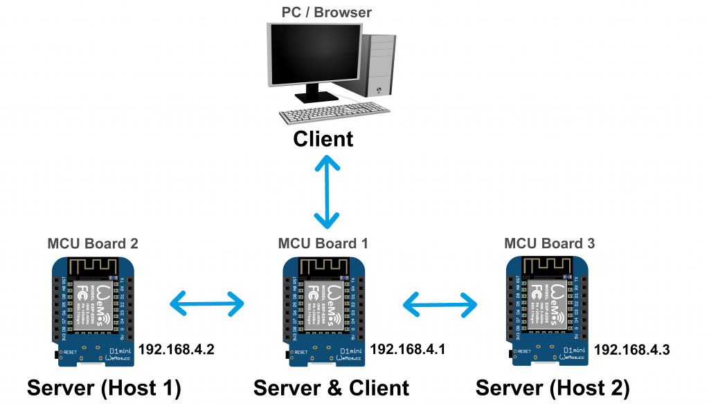
I have chosen three Wemos D1 Mini Boards for illustration. But you can also – thanks to the universal HTTP – use a mixture of different MCUs.
So that you don’t get confused about which board you load which sketch onto, I recommend opening the Arduino IDE several times (“create multiple instances”). Then you can select a separate serial port for each instance. In any case, I find this easier than changing the port within an instance.
Server Sketch
We can keep the sketches for the servers (hosts) simple, since they should only send their measured values.
#include <ESP8266WebServer.h>  // use <WebServer.h> for ESP32
// #include <WiFi.h> // for ESP32

const char* ssid = "ESP8266_Server";
const char* pass = "blablablabla";

IPAddress ip(192,168,4,2);  // ip(192,168,4,3); for second host
IPAddress gateway(192,168,4,1);
IPAddress subnet(255,255,255,0);

ESP8266WebServer server(80); // WebServer server(80); for ESP32

void setup(){
  WiFi.config(ip, gateway, subnet);
  WiFi.begin(ssid, pass);

  server.on("/voltage",voltage);
  server.begin();
}

void loop(){
  server.handleClient();
}

void voltage(){
  float measuredValue_1 = analogRead(A0)/1024.0 * 3.3;
  String message = String(measuredValue_1, 2);
  server.send(200, "text/html", message);
}
Sketch for the Access Point MCU (client and server)
The special feature is that this member of the network is a client in relation to the two hosts and a server in relation to the PC.
The PC sends a get request to the AP MCU every 10 seconds because I set it that way via “refresh”. For “real” projects, it is better not to set the frequency so high.
Every 15 seconds, the AP MCU sends GET requests to the hosts to collect the measured values. This is also a quite high frequency. Lower it to the level you need. This saves power and avoids “collisions”.
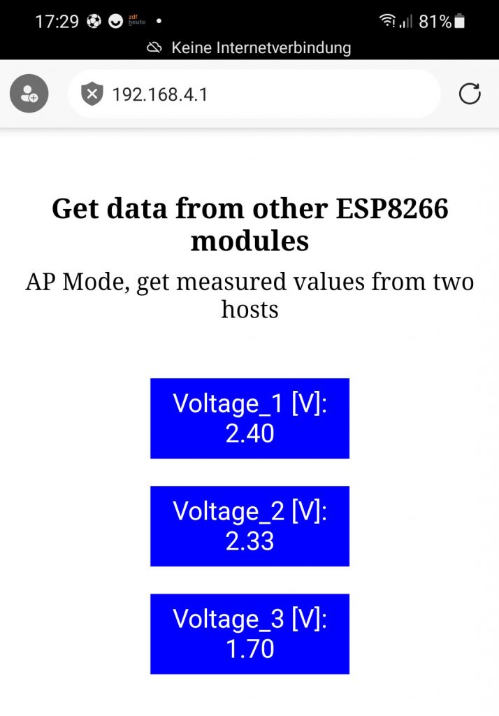
Via the browser you can then finally view all measured values. At the top right you can see what the result looks like on my smartphone.
And here is the sketch:
#include <ESP8266WebServer.h> // use <WebServer.h> for ESP32
// #include <WiFi.h> // for ESP32
#define HOST_1 0
#define HOST_2 1

const char* ssid = "ESP8266_Server";
const char* pass = "blablablabla";

const char* host_1 = "192.168.4.2";
const char* host_2 = "192.168.4.3";

String voltage[2] = {"",""};
unsigned long requestPeriod = 15000;

IPAddress ip(192,168,4,1);
IPAddress gateway(192,168,4,1);
IPAddress subnet(255,255,255,0);

ESP8266WebServer server(80); // WebServer server(80); for ESP32

String headAndTitle = "<head><style>"
                        ".blueBox {"
                          "background-color: blue;"
                          "color: white;"
                          "width: 350px;"
                          "padding: 20px;"
                          "text-align: center;"
                          "font-size: 50px;"
                          "font-family: arial;"
                        "}"
                      "</style>"
                      "</head><meta http-equiv=\"refresh\" content=\"10\"></head>"
                      "</BR></BR><h1 align=\"center\">Get data from other ESP8266 modules</h1></div>"
                      "<div align=\"center\">AP Mode, get measured values from two hosts</BR></BR></div>";

void setup(){
  WiFi.softAPConfig(ip, gateway, subnet);
  WiFi.softAP(ssid, pass);


  server.on("/",handleRoot);
  server.begin();
}

void loop(){
  static unsigned long startTime = millis();
  server.handleClient();
  if ((millis() - startTime) > requestPeriod){
    requestESP8266(HOST_1);
    requestESP8266(HOST_2);
    startTime = millis();
  }
}

void handleRoot(){
  String message = "";
  message += headAndTitle;
  message += "<div align=\"center\";>";
  float measuredValue_1 = analogRead(A0)/1024.0 * 3.3;

  message += "</BR><div class=\"blueBox\">";
  message += "Voltage_1 [V]: </BR>";
  message += String(measuredValue_1, 2);
  message += "</div>";

  message += "</BR><div class=\"blueBox\">";
  message += "Voltage_2 [V]: </BR>";
  message += voltage[HOST_1];
  message += "</div>";

  message += "</BR><div class=\"blueBox\">";
  message += "Voltage_3 [V]: </BR>";
  message += voltage[HOST_2];
  message += "</div></div>";
  server.send(200, "text/html", message);
}

void requestESP8266(int hostNo){
  WiFiClient client;
  String host = "";
  if(hostNo == HOST_1){
    if (!client.connect(host_1, 80)) {
      host = host_1;
      return;
    }
  }
  if(hostNo == HOST_2){
    if (!client.connect(host_2, 80)) {
      host = host_2;
      return;
    }
  }
  String url = "/voltage";

  client.print(String("GET ") + url + " HTTP/1.1\r\n" +
               "Host: " + host + "\r\n" +
               "Connection: close\r\n\r\n");
  unsigned long lasttime = millis();
  while (!client.available() && ((millis() - lasttime) < 3000)){
    delay(1);
  }
  while (client.available()) {
    String line = client.readStringUntil('\r');
    if(line != ""){
      voltage[hostNo] = line;
    }
  }
}
The sketch doesn’t really contain anything new. I hope that it is reasonably comprehensible.
Networking multiple MCUs with router as access point
Now we change the last version so that the router is the access point. In addition, the direct query of the two host MCUs should also produce an appealing image in the browser. The MCU that collects the values from the hosts, I have called “Main” here:

Sketch for the Host MCUs
#include <ESP8266WebServer.h>  // <WebServer.h> for ESP32
// #include <WiFi.h> // for ESP32

const char* ssid = "Your SSID";
const char* pass = "Your Password";

IPAddress ip(192,168,178,111); // ip(192,168,178,112); for second host
IPAddress gateway(192,168,178,1);
IPAddress subnet(255,255,255,0);

ESP8266WebServer server(80); // WebServer server(80); for ESP32

String headAndTitle = "<head><style>"
                        ".blueButton {"
                          "border: none;"
                          "color: white;"
                          "width: 400px;"
                          "padding: 20px;"
                          "text-align: center;"
                          "margin: 20px 200px;"
                          "background-color: blue;"
                          "font-size: 50px;"
                        "}"
                      "</style>"
                      "</head><meta http-equiv=\"refresh\" content=\"15\"></head>"
                      "</BR></BR><h1 align=\"center\">ESP8266 Host 1</h1></div>";

void setup(){
  WiFi.begin(ssid, pass);
  WiFi.config(ip, gateway, subnet);

  server.on("/",handleRoot);
  server.on("/voltage",voltage);
  server.begin();
}

void loop(){
  server.handleClient();
}

void handleRoot(){
  String message = "";
  message += headAndTitle;
  message += "<div align=\"center\";>";
  float measuredValue_1 = analogRead(A0)/1024.0 * 3.3;
  message += "</BR><button class=\"button blueButton\">";
  message += "Voltage_2 [V]: </BR>";
  message += String(measuredValue_1, 2);
  message += "</button>";
  message += "</div>";
  server.send(200, "text/html", message);
}

void voltage(){
  float measuredValue_1 = analogRead(A0)/1024.0 * 3.3;
  String message = String(measuredValue_1, 2);
  server.send(200, "text/html", message);
}
So the host MCUs provide two pages here. When the main path is called up, the nice page is transmitted, when “/voltage” is called up, only the bare measured value is sent.
Sketch for the “main” MCU
#include <ESP8266WebServer.h>  // <WebServer.h> for ESP32
// #include <WiFi.h> // for ESP32
#define HOST_1 0
#define HOST_2 1

const char* ssid = "Your SSID";
const char* pass = "Your Password";

const char* host_1 = "192.168.178.111";
const char* host_2 = "192.168.178.112";

String voltage[2] = {"",""};
unsigned long requestPeriod = 15000;

IPAddress ip(192,168,178,110);
IPAddress gateway(192,168,178,1);
IPAddress subnet(255,255,255,0);

ESP8266WebServer server(80);  // WebServer server(80); for ESP32

String headAndTitle = "<head><style>"
                        ".blueBox {"
                          "background-color: blue;"
                          "color: white;"
                          "width: 350px;"
                          "padding: 20px;"
                          "text-align: center;"
                          "font-size: 50px;"
                          "font-family: arial;"
                        "}"
                      "</style>"
                      "</head><meta http-equiv=\"refresh\" content=\"10\"></head>"
                      "</BR></BR><h1 align=\"center\">Get data from other ESP8266 modules</h1></div>"
                      "<div align=\"center\">STA Mode, get measured values from two hosts</BR></BR></div>";

void setup(){
  Serial.begin(115200);
  WiFi.config(ip, gateway, subnet);
  WiFi.begin(ssid, pass);

  server.on("/",handleRoot);
  server.begin();
}

void loop(){
  static unsigned long startTime = millis();
  server.handleClient();
  if ((millis() - startTime) > requestPeriod){
    requestESP8266(HOST_1);
    requestESP8266(HOST_2);
    startTime = millis();
  }
}

void handleRoot(){
  String message = "";
  message += headAndTitle;
  message += "<div align=\"center\";>";
  float measuredValue_1 = analogRead(A0)/1024.0 * 3.3;

  message += "</BR><div class=\"blueBox\">";
  message += "Voltage_1 [V]: </BR>";
  message += String(measuredValue_1, 2);
  message += "</div>";

  message += "</BR><div class=\"blueBox\">";
  message += "Voltage_2 [V]: </BR>";
  message += voltage[HOST_1];
  message += "</div>";

  message += "</BR><div class=\"blueBox\">";
  message += "Voltage_3 [V]: </BR>";
  message += voltage[HOST_2];
  message += "</div></div>";
  server.send(200, "text/html", message);
}

void requestESP8266(int hostNo){
  WiFiClient client;
  String host = "";
  if(hostNo == HOST_1){
    host = host_1;
    if (!client.connect(host_1, 80)) {
      Serial.println("connection failed to host 2");
      return;
    }
  }
  if(hostNo == HOST_2){
    host = host_2;
    if (!client.connect(host_2, 80)) {
      Serial.println("connection failed to host 3");
      return;
    }
  }
  String url = "/voltage";
  Serial.print("Requesting URL: ");
  Serial.println(url);


  client.print(String("GET ") + url + " HTTP/1.1\r\n" +
               "Host: " + host + "\r\n" +
               "Connection: close\r\n\r\n");
  unsigned long lasttime = millis();
  while (!client.available() && ((millis() - lasttime) < 3000)){
    delay(1);
  }
  while (client.available()) {
    String line = client.readStringUntil('\r');
    if(line != ""){
      voltage[hostNo] = line;
    }
  }
  Serial.println();
  Serial.println("closing connection to ESP8266");
}
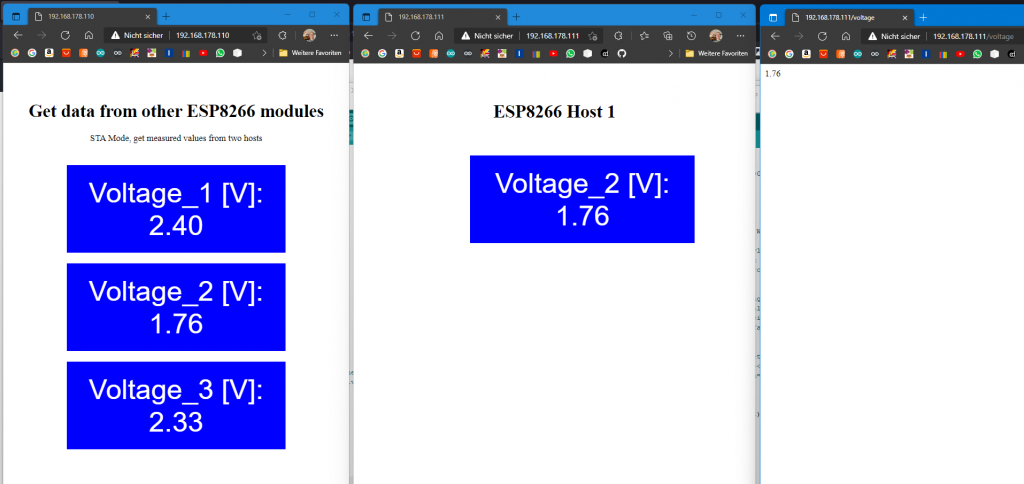
Now you can query the collected metrics, the main path of the hosts, or just the raw metrics of a host. Here are all three variants in parallel:
Acknowledgement
As usual, I have again used several images from Pixabay:
- PC, router, smartphone and Wi-Fi icon are from: OpenClipart-Vectors.
- I owe the tablet to fajarbudi86.
Appendix: If the refresh is disruptive
In my examples, the instruction to switch an LED on or off is repeated with every refresh. This is not a problem here, but it becomes one if the instruction is not to be repeated. A simple example would be toggling an LED. The solution is to trigger the action as usual by clicking on the link and then jumping back to the main directory. This is done in the following sketch using line 104. The page structure must take place in the main directory accordingly, i.e. in handleRoot().
#include <ESP8266WebServer.h> // <WebServer.h> for ESP32
// #include <WiFi.h> // for ESP32

int led[3] = {D5,D6,D7};
bool led_status[3] = {false};
const char* ssid = "your SSID";
const char* pass = "your password";

IPAddress ip(192,168,178,110);
IPAddress gateway(192,168,178,1);
IPAddress subnet(255,255,255,0);

ESP8266WebServer server(80);  // WebServer server(80); for ESP32

String headAndTitle = "<head><style>"
                        ".button {"
                          "border: none;"
                          "color: white;"
                          "width: 350px;"
                          "padding: 20px;"
                          "text-align: center;"
                          "margin: 20px 200px;"
                        "}"
                        ".greenButton {background-color: green; font-size: 64px;}"
                        ".greenButton:hover {background-color: darkgreen; font-size: 64px;}"
                        ".redButton {background-color: red; font-size: 64px;}"
                        ".redButton:hover {background-color: darkred; font-size: 64px;}"
                        ".blueBox {"
                          "background-color: blue;"
                          "color: white;"
                          "width: 350px;"
                          "padding: 20px;"
                          "text-align: center;"
                          "font-size: 50px;"
                          "font-family: arial;"
                          "margin: 20px 200px;"
                        "}"
                      "</style>"
                      "</head><meta http-equiv=\"refresh\" content=\"5\"></head>"
                      "</BR></BR><h1 align=\"center\">Control your ESP8266 by Browser</h1></div>"
                      "<div align=\"center\">Toggle three LEDs and get measured value</BR></BR></div>";

String led0_1= "<a href=\"/toggle_led_0\"><button class=\"button greenButton\">LED0 On</button></a>";
String led0_0= "<a href=\"/toggle_led_0\"><button class=\"button redButton\">LED0 Off</button></a>";
String led1_1= "</BR><a href=\"/toggle_led_1\"><button class=\"button greenButton\">LED1 On</button></a>";
String led1_0= "</BR><a href=\"/toggle_led_1\"><button class=\"button redButton\">LED1 Off</button></a>";
String led2_1= "</BR><a href=\"/toggle_led_2\"><button class=\"button greenButton\">LED2 On</button></a>";
String led2_0= "</BR><a href=\"/toggle_led_2\"><button class=\"button redButton\">LED2 Off</button></a>";

void setup(){
    for (int i=0; i<3; i++){
        pinMode(led[i], OUTPUT);
        digitalWrite(led[i], LOW);
    }

    WiFi.config(ip, gateway, subnet);
    WiFi.begin(ssid, pass);

    server.on("/",handleRoot);
    server.on("/toggle_led_0", toggleLED0);
    server.on("/toggle_led_1", toggleLED1);
    server.on("/toggle_led_2", toggleLED2);
    server.begin();
}

void loop(){
  server.handleClient();
}

void handleRoot() {
  String message = "";
  message += headAndTitle;
  message += "<div align=\"center\";>";

  (led_status[0]==true)?(message += led0_0):(message += led0_1);
  (led_status[1]==true)?(message += led1_0):(message += led1_1);
  (led_status[2]==true)?(message += led2_0):(message += led2_1);

  float measuredValue = analogRead(A0)/1024.0 * 3.3;
  message += "</BR><div class=\"blueBox\">";
  message += "Voltage [V]: </BR>";
  message += String(measuredValue, 2);
  message += "</div>";
  message += "</div>";
  server.send(200, "text/html", message);
}

void toggleLED0(){
    toggleLEDNo(0);
}

void toggleLED1(){
    toggleLEDNo(1);
}

void toggleLED2(){
    toggleLEDNo(2);
}

void toggleLEDNo(int ledPin){
    digitalWrite(ledPin, !digitalRead(ledPin));
    led_status[ledPin] = !digitalRead(led[ledPin]);
    digitalWrite(led[ledPin], led_status[ledPin]);
    String goToRoot = "<head><meta http-equiv=\"refresh\" content=\"0; URL=//192.168.178.110\"></head>"; // go to Root
    server.send(200, "text/html", goToRoot);
}
Guten Tag,
Ich tutoriere an der Universität einen Kurs über Mikrokontroller und eine der Aufgaben war die Steuerung von LEDs beziehungsweise Sensoren über einen Webserver. Ich wollte deshalb nachfragen, ob ich Ihren Code (mit Quellenangabe) als Grundlage für eine Musterlösung verwenden könnte. Vielen Dank und freundliche Grüße.
Hallo Luke, sehr gerne. Es freut mich immer, wenn meine Arbeit sinnvolle Verwendung findet!
Vielen Dank für die schnelle Antwort!