About this post
In this article I would like to introduce the Wemos D1 Mini Board. Strictly speaking, it is a board family, but its members are not very different. So, when I talk about the Wemos D1 Mini, I always mean the whole family.
First, I will look at what the Wemos D1 Mini Board is, what features it has, and how the variants differ. Then I will show you how to integrate the board into the Arduino IDE and what are the differences to the Arduino (UNO) board. Finally, there is a small speed test.
What is the Wemos D1 Mini Board?
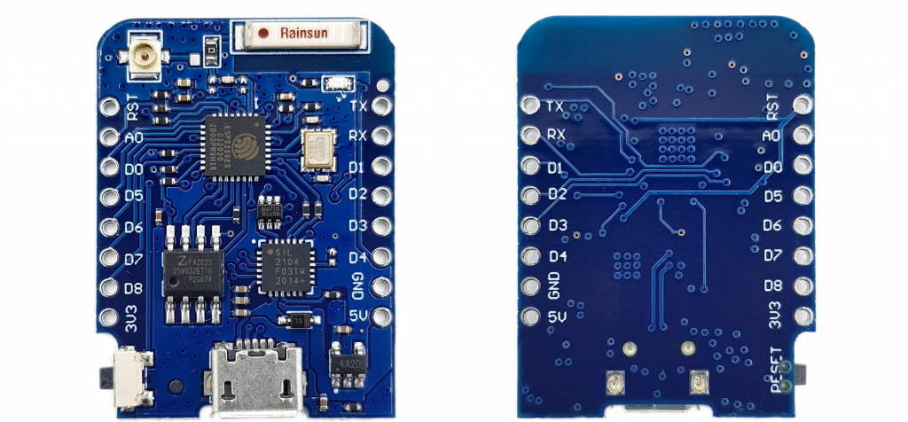
The heart of a Wemos D1 mini board is an ESP8266EX, an ESP8266 12-F or an ESP8285 chip, depending on the version. These are powerful 32-bit microcontrollers with integrated Wi-Fi interface.
So, what the ATmega328P is for the Arduino UNO board, the ESP8266/ESP8285 is for the Wemos board. And just as the ATmega328P is “stand-alone” programmable (I have reported on it here), you can also program the ESP8266/ESP8285 as such. But for this purpose, you need some additional components such as USB-to-serial adapter. In addition, not for everyone enjoys soldering SMD components like the ESP8266EX. It’s easier to use a development board like the Wemos D1 Mini.
Name confusion
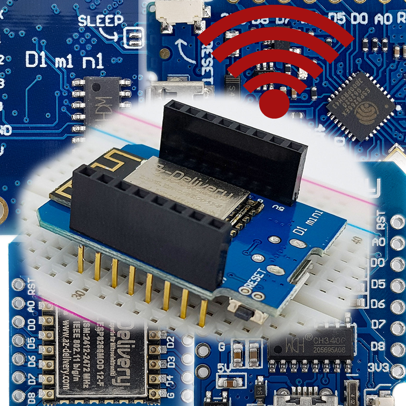
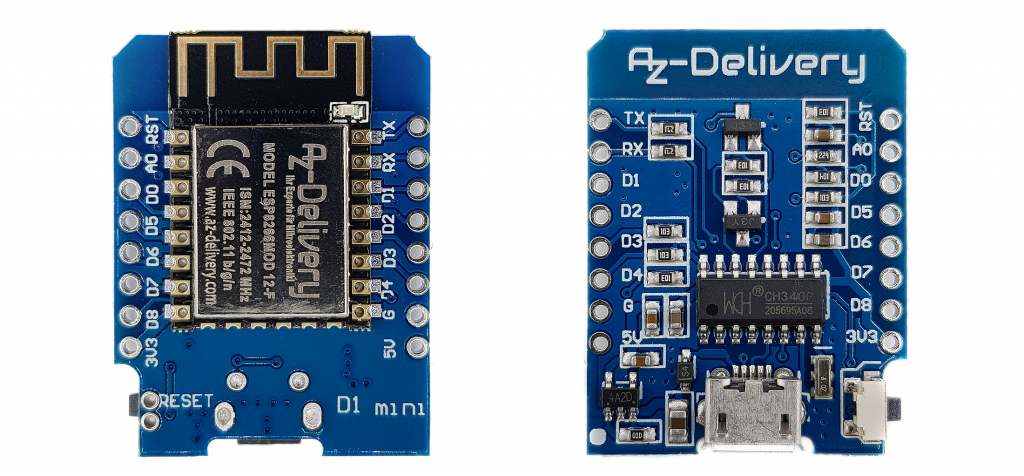
If you search for the term “D1 Mini”, you will find a bunch of boards with different names. For example, this could be the Lolin D1 Mini, the AZ-Delivery D1 Mini (NodeMCU) shown above, but of course also the Wemos D1 Mini. The “first name” is only a brand or manufacturer name and in my experience does not matter. In the further course of the article I prefer to use the name Wemos D1 Mini, as this is the original.
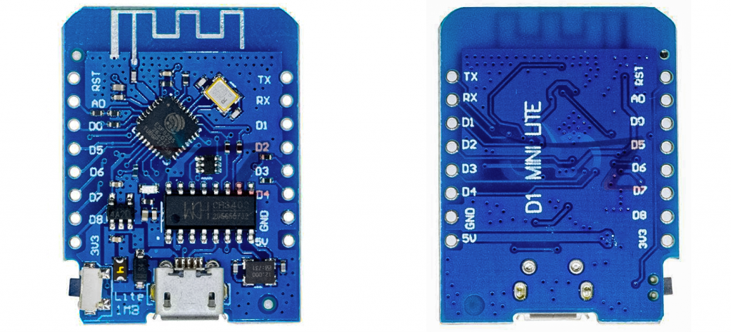
In addition, these boards have different “surnames”, e.g. D1 Mini Pro, D1 Mini V3 or D1 Mini Lite. There are indeed differences here.
Key technical features of the Wemos D1 Mini Boards
The following technical features are common to all Wemos D1 mini boards:
- You have several options forpowering the boards. Either apply 2.5 to 3.6 volts to the 3.3 volt pin, 3 to 7 volts to the 5 volt pin, or power the board via the USB micro port. The underlying microcontrollers run at 2.5 – 3.6 volts.
- The power comsumption of the Wemos D1 Mini Boards is comparatively high at around 70 milliamps. When transmitting via Wi-Fi, it even increases to several hundred milliamperes.
- The Wemos D1 Mini Boards have the interfaces I2C, SPI and UART.
- The Wi-Fi meets the specifications 802.11 b/g/n (2.4 GHz) with WPA/WPA2 PSK.
- The clock is 80 or 160 MHz.
- There are 11 I/O pins, all except D0 are PWM, I2C and One-Wire capable, Imax is 12 mA.
- The maximum output voltage at the I/O pins is 3.3 volts.
- 1 analog input with 10 bit resolution, max. 3.2 Volts (!)
- Flash memory:1 – 16 MB.
The different Wemos D1 Mini Boards

The boards differ mainly in the microcontroller used, the flash memory and the antenna. In addition, there are differences in the USB-to-serial adapter. Some boards use the CH340G, others use the CP2104. This difference is relevant in that different drivers are required. From the name of the board it cannot be concluded with certainty which USB-serial adapter is used.
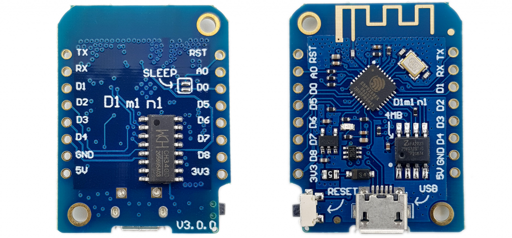

Wemos D1 Mini V4.0.0 vs. V3.0.0
The latest representative of the series is the Wemos D1 Mini V4.0.0 (short: D1 Mini V4). The changes compared to the Wemos D1 Mini 3.0.0 (short: D1 Mini V3) are not huge:
- The USB port has been changed from USB-Micro-B to USB-C.
- The 5V connection is now called VBUS on the D1 Mini V4. There is no longer a diode between the 5V power supply via USB and VBUS. You can continue to supply the Wemos D1 Mini V4 with voltages > 5V at VBUS, but you should then disconnect it from the USB connection!
- The D1 Mini V4 has a QWIIC connector for the convenient use of I2C devices.
- The SLEEP solder pad offers the option of connecting GPIO16 (D0) to Reset. This is required to wake the D1 mini from deep sleep. The D1 mini V4 has an additional 470 Ohm resistor installed between D0 and Reset for protection.
- I think it’s a bit of a shame that version 4 only uses the GPIO designations and not the “Dx” pin designations.
Preparations
Pin header
Normally you will receive pin headers with your board. With AZ-Delivery you will receive various bars (no, I am not paid by them!):
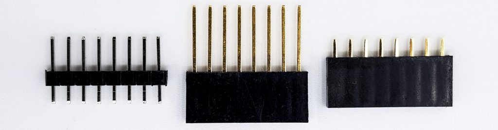
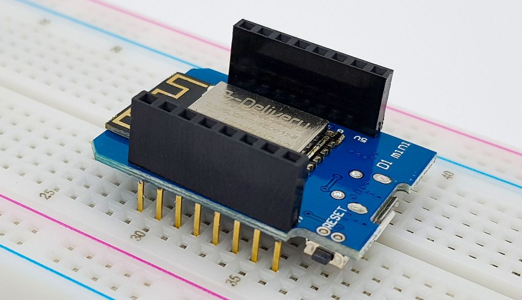
Personally, I find the socket strips with the long pins handy for experimenting because you can fix the board well on the breadboard and also use the sockets:
Integrating the Wemos D1 Mini Board into the Arduino IDE
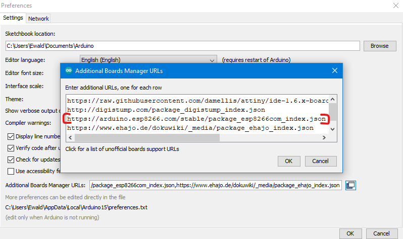
Before you start you have to introduce the Wemos D1 Mini Board to the Arduino IDE. To do this, go to File > Preferences and click on the icon next to “Additional Board Manager URLs”. In the window that pops up, enter the following on a separate line:
https://arduino.esp8266.com/stable/package_esp8266com_index.json
Then you go to Tools – > Board – > Board Manager, search for “esp8266” and install the package:
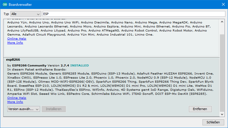
Then you restart the Arduino IDE.
If your board is detected by Windows, it should appear like this or similar in the Device Manager:

If your board is not recognized, then you are probably missing the driver for the USB-to-Serial Adapter. The driver for the CH340G can be downloaded here or here (click on the download icon). Don’t bother with the name “CH341SER”. You can get the driver for the CP2104 here.
A small test
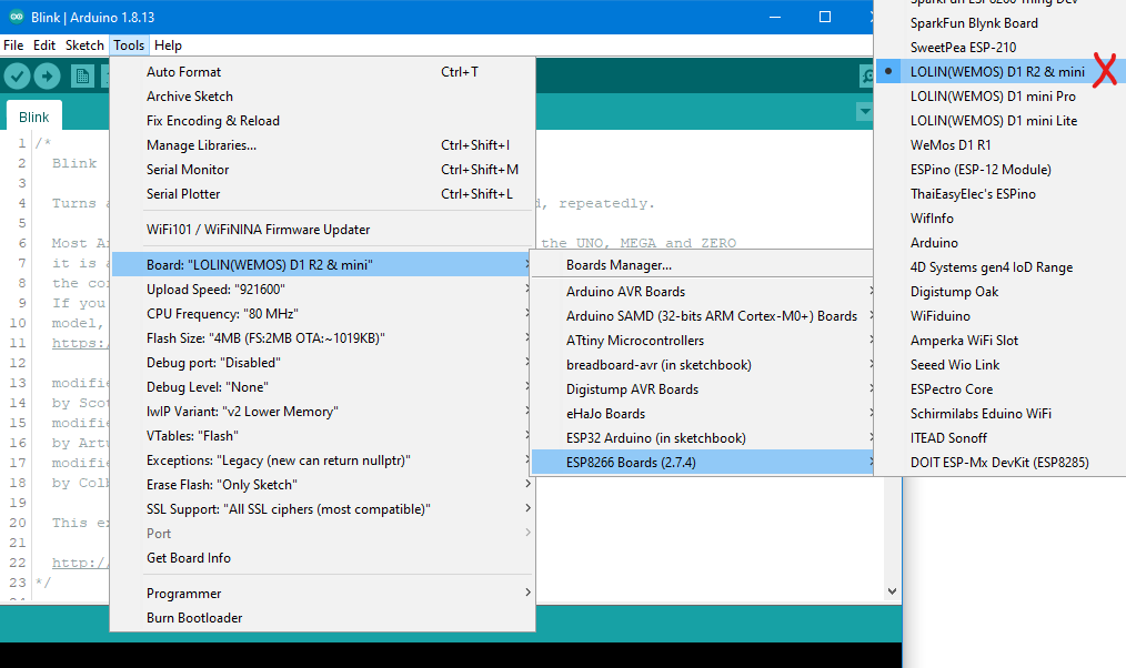
Open the Blink Example sketch: File – > Examples – > Basics – > Blink. Then select the correct board in Tools – > Boards:
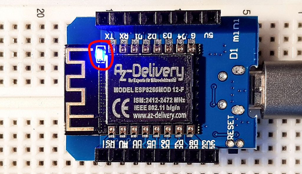
Finally, you have to select the right port, and then you are ready to upload the sketch. If all goes well, the on-board LED should flash now:
Problems using clone boards
With some clones of the Wemos boards, I sometimes had problems uploading programs. In this case, it helped me to press the reset button during compilation and release it when the actual upload is starting.
Using the Wemos D1 Board
I will now go into the most important basic functions, paying particular attention to the differences with the Arduino (Uno).
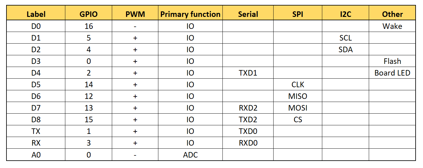
Also on the Wemos D1 Mini Board some pins have multiple functions:
Restrictions for the use of some pins
Some pins have special functions, so there are certain restrictions for them:
- D0 (GPIO 16): The pin is needed to wake up from DeepSleep. It also gives a short high signal when booting.
- D3 (GPIO 0): If this pin is pulled to LOW during boot, the ESP8266 changes into firmware programming mode.
- D4 (GPIO 2): The pin must not be pulled to LOW during boot.
- D8 (GPIO 15): Must not be pulled HIGH during boot.
digitalWrite() / analogWrite()
For the digitalWrite() function, first note that the HIGH signal at the corresponding output is 3.3 volts. The current must not exceed 12 milliamps.
You can use the pins D0 – D8 and RX / TX as input or output pins. This means that you have a total of 11 pins at your disposal. To address them, you can use their designation or GPIO number. The following commands have the same effect:
digitalWrite(D2, HIGH); / digitalWrite(4, HIGH);
For pin D4, it should be noted that it is connected to the board LED. However, in such a way that the board LED lights up when D4 is LOW.
The pinMode is set as usual. But there is one particularity. If you want to activate the pull-down resistor of D0 (GPIO 16), then you have to do like this: pinMode(D0, INPUT_PULLDOWN_16).
analogWrite() is available for all I/O pins. This also applies to the pin D0, which has otherwise limited PWM capabilities. In contrast to the Arduino UNO, the resolution is 10 bits. This means that analogWrite(pin, 1023) delivers the full voltage.
Update: since ESP8266 Arduino Core version 3.0 the default resolution for analogWrite() is 8 bit due to compatibility issues. To return to the old behavior, you just have to add analogWriteRange(1023); to the setup (see also here).
digitalRead() / analogRead()
digitalRead() works like the Arduino with all pins D0 – D8. The pins RX and TX have their own peculiarities. Therefore, I would not use them for this purpose.
The Pin A0 is the only analog input. Actually, the analog input of the ESP8266 can only tolerate a maximum of 1 volt. However, on the Wemos D1 mini boards a voltage divider (100 kOhm / 220 kOhm) is connected upstream, so that the maximum voltage is 3.2 volts. The resolution is 10 bits. This results in the following for the voltage U:
![\[ U\;[\text{V}]=3.2 \cdot \frac{analogRead(\text{A0})}{1024} \]](https://wolles-elektronikkiste.de/wp-content/ql-cache/quicklatex.com-974402f6be440fc615728ab9c63d2fd6_l3.png "Rendered by QuickLaTeX.com")
It is interesting that you actually get 1024 for the maximum voltage and not 1023 as with the Arduino UNO. For the latter it’s one of my favorite topics that you have to divide by 1023 and not 1024 when calculating the voltage. So that’s different here.
I like the function analogRead() on the Wemos D1 Mini Boards much more than that on the Arduino UNO. With the Arduino UNO, the analogRead values fluctuate by +/- two units, even when a stable voltage source is connected. The values determined with the Wemos D1 Mini, on the other hand, do not fluctuate at all.
Interrupts
AApart from the general restrictions mentioned above, you can use any pin of the Wemos D1 Mini Board for interrupts. An interrupt is set up as usual via
attachInterrupt(digitalPinToInterrupt(Pin), ISR, mode);
and
detachInterrupt(digitalPinToInterrupt(Pin));
deactivates it again. For mode, you can choose from:
- RISING
- FALLING
- CHANGE
- LOW
- HIGH
The first three options trigger the interrupt with the signal edge, LOW and HIGH trigger again and again as long as the level of the pin corresponds to the setting.
In addition, there are two things to note about the Interrupt Service Routine (ISR):
- The ISR must be placed before the Setup.
- You have to insert the attribute
IRAM_ATTRbefore the function name of the ISR, i.e.:void IRAM_ATTR ISRname() {.....}.
You may also see ICACHE_RAM_ATTR in older code. It still works, but it is deprecated.
I2C with the Wemos D1 Mini Board
If you activate I2C with Wire.begin(), then D1 serves as SCL and D2 as SDA. However, it is not a problem to select other pins according to the scheme Wire.begin(SDA-PIN,SCL-PIN).
The Wemos D1 Mini boards are capable of the Fast Mode (400 kHz). Beyond that, it gets tight.
You have to be careful with the voltage levels of the I2C connection. If you use an I2C component that runs on 5 volts, you need a voltage divider, or you take a logic level converter like this:

SPI with the Wemos D1 Mini Board
There is not so much to say about SPI. The connections can be found in Table 2.
Serial interface
You use the pins TX and RX for serial communication like on the Arduino UNO. You can also use pins D7 and D8 (= GPIO 13 / RXD2 or GPIO 15 / TXD2) instead. All you have to do is insert the instruction Serial.swap() after Serial.begin() in the setup.
Attention – biting watchdog
Take the following sketch, which is rather pointless in itself, and load it unchanged onto your Wemos D1 Mini Board.
In the setup, the board LED flashes ten times at fast frequency. This is simply to visualize the starting point of the sketch. In the main loop, your Wemos D1 Mini Board is waiting for a HIGH signal on D1, e.g. through a button or sensor. If there is no signal, your board should run the while() loop forever.
void setup() {
  pinMode(D1, INPUT); // Actually redundant, since this state is default
  pinMode(LED_BUILTIN, OUTPUT);
  for(int i=0; i<10; i++){
    digitalWrite(LED_BUILTIN, LOW);
    delay(50);
    digitalWrite(LED_BUILTIN, HIGH);
    delay(50);
  }
  //ESP.wdtDisable();
}

void loop() {
  while(!digitalRead(D1)){
    //delay(0);
  }
}
But if you run the sketch, you will see the flashing LED restarting about every three seconds. Here a security mechanism strikes and this is called watchdog timer. I have reported about watchdog timers in another post. The short version is: a watchdog timer is a counter that, if not reset in time, overflows and then triggers a reset. It thus watches over the microcontroller and ensures, for example, that a crashed program is restarted.
The Wemos D1 Mini Board, or more precisely the ESP8266, has a software and a hardware watchdog timer. The software watchdog is activated by default and runs over approximately every 3 seconds if it’s not reset. The reset is done by certain functions, e.g. when you restart the main loop, perform a delay() or – quite explicitly – by ESP.wdtFeed() (the watchdog is fed). Uncomment line 15, and you’ll see that your board isn’t constantly restarting.
Extending the watchdog period
You can extend the time until the reset by turning off the software watchdog. For this purpose, uncomment line 10. However, the hardware watchdog now bites about every 8 seconds. The hardware watchdog cannot be turned off and the watchdog periods cannot be extended further.
What is this is good for?
The ESP8266 regularly performs routines that take care of the Wi-Fi function. For example, this happens when the main loop restarts or when a delay() is executed. If it is not given the opportunity to do so, the ESP8266 prefers to restart to ensure the correct Wi-Fi function. However, this in turn can lead to problems like in the sketch above.
Wi-Fi – Functions
One of the main reasons for choosing a Wemos D1 Mini Board is, of course, its Wi-Fi functionality. Since this a quite extensive topic I have covered it in a separate article. As an “appetizer” I would like to show a simple example here. The following sketch allows you to switch an LED connected to D1 via your browser.
#include "ESP8266WebServer.h"
#define LEDPIN D1
const char* ssid = "Deine SSID";
const char* pass = "Dein Passwort";
IPAddress ip(192,168,178,xxx); // xxx = wählt eine frei IP in eurem Heimnetz
IPAddress gateway(192,168,178,1);
IPAddress subnet(255,255,255,0);
ESP8266WebServer server(80);
String led1= "<a href=\"/led_an\">LED An</a>";
String led0= "<a href=\"/led_aus\">LED Aus</a>";
void handleRoot() {
String message="<h1>Testprogramm - Minimalprogramm ESP8266</h1>";
message += "Hallo ......, das ist ein Gruß vom ESP8266 Server</BR></BR>";
message += led1;
server.send(200, "text/html", message);
}
void ledan(){
digitalWrite(LEDPIN, HIGH);
server.send(200, "text/html", led0);
}
void ledaus(){
digitalWrite(LEDPIN, LOW);
server.send(200, "text/html", led1);
}
void setup(){
pinMode(LEDPIN, OUTPUT);
digitalWrite(LEDPIN, LOW);
// Serial.begin(9600);
// Serial.println("Testprogramm - Minimalprogramm ESP8266");
// Serial.print("Verbinde mich mit Netz: ");
// Serial.println(ssid);
WiFi.begin(ssid, pass);
WiFi.config(ip, gateway, subnet);
// while(WiFi.status() != WL_CONNECTED){
// delay(500); Serial.print(".");
// }
// Serial.println("");
// Serial.println("WiFi Verbindung aufgebaut");
// Serial.print("Eigene IP des ESP-Modul: ");
// Serial.println(WiFi.localIP());
server.on("/",handleRoot);
server.on("/led_an", ledan);
server.on("/led_aus", ledaus);
server.begin();
// Serial.println("HTTP Server wurde gestartet!");
}
void loop(){
server.handleClient();
}
Explanations for this sketch and other examples can be found in my article about the ESP8266 ESP-01. Or do you want to be informed on your smartphone when certain sensor data exceeds a limit? No problem with IFTTT (if this then that) – I have described this here.
Speed test
Finally, I would like to address the question of how fast the Wemos D1 Mini boards actually are. 80 or 160 MHz sound quite promising compared to the 16 MHz of the Arduino UNO.
digitalRead();
First, I determined the speed of the digitalRead() function. To achieve this, I had the board perform this function a million times. I measured the time required for this by using the millis() function.
void setup() {
  Serial.begin(9600);
}

void loop() {
  long startTime = millis();
  for(long i=0; i<1000000; i++){
    digitalRead(10);
  }
  long duration = millis() - startTime;
  Serial.println(duration);
}
Here are the results for 1 million reads on the Arduino UNO and the D1 Mini at 80 and 160 MHz respectively:
- Arduino UNO : 3710 ms
- D1 Mini at 80 MHz: 588 ms
- D1 Mini at 160 MHz: 325 ms
In a first rough approximation, this actually corresponds to the ratio of the clock rates.
Mathematical operations
For the speed measurement of mathematical operations, I chose pow(i,0.5) which is known to be computationally intensive:
void setup() {
  Serial.begin(9600);
}

void loop() {
  long startTime = millis();
  float f = 0.0;
  for(long i=0; i<50000; i++){
    f = pow(i,0.5);
  }
  long duration = millis() - startTime;
  Serial.println(duration);
  Serial.println(f);
}
By the way, the command Serial.println(f) is important because the compiler “optimized” the calculation of f by just ignoring it when f is not used. I was very surprised when I always got “0” as a result for “duration” until I noticed that f must be used.
Here are the results:
- Arduino UN : 17119 ms
- D1 Mini at 80 MHz: 926 ms
- D1 Mini at 160 MHz: 463 ms
In this calculation process the ESP8266 chip is even faster than the ATmega328P as it could be explained by the clock rate. Here, an architectural advantage comes into play. In any case, the difference is really big. But whether you really need it is, of course, a different matter.
Deep Sleep
To put the D1 Mini Board into deep sleep and wake it up again, connect the contacts of the SLEEP solder pad. The function ESP.deepSleep(time); sends the board into deep sleep for the period “time” (in microseconds). Try it with the following sketch:
void setup() {
  pinMode(LED_BUILTIN, OUTPUT);
  for(int i=0; i<10; i++){
    digitalWrite(LED_BUILTIN, HIGH);
    delay(50);
    digitalWrite(LED_BUILTIN, LOW);
    delay(50);
  }
  ESP.deepSleep(10e6); // sleep for 10 x 10^6 µs = 10s
}

void loop() {}