
About the post
After my articles about the 8-bit timers and the 16-bit timer of the Arduino UNO or the ATmega328P I would like to complete this topic with the watchdog timer. This article is about:
- What is a watchdog timer and why do I need it?
- The watchdog timer of the Arduino UNO (and other AVR MCUs)
- The problem with the Arduino Pro Mini
- ESP8266’s watchdog timer
What is a watchdog timer?
Under certain conditions, a microcontroller can hang up just like a PC due to unexpected conditions or programming errors. Most of the time, programming errors become immediately noticeable, but sometimes this happens later under special conditions that were not considered during programming. Also, errors in peripherals, such as communication lines or sensors, can cause the sketch to hang in a program loop.
Simply put, the watchdog timer watches over the sketch by regularly expecting signs of life from it. If these are omitted, depending on the setting and microcontroller, a reset is performed after an adjustable time, an interrupt is triggered or both. More precisely, the watchdog timer is an automatic counter that triggers the mentioned actions when it reaches its limit, if it is not reset before.
For example, an interrupt before the reset can be used to
- ensure safe conditions for the controlled system
- save parameters on an EEPROM for error analysis
- save the status of the program so that it continues its work at the right step after the reset (simple example: control of a washing machine)
The watchdog timer of the Arduino (UNO)
The following guide applies to the whole ATmega 48 / 88 / 168 / 328 / 328P family. You can also find this in the data sheet from page 60. In principle, the information also applies to the other representatives of the AVR microcontrollers. However, not every time-out is available for every model. More information about the time-outs can be found here.
Settings
The watchdog timer of the Arduino UNO or the ATmega 328P is not controlled by the system clock like the other timers discussed earlier, but via a separate 128 kHz oscillator. This makes the sketches easier to transfer from one controller to another or if you change the system clock.
You choose the settings of the watchdog timer in the Watchdog Timer Control Register WDTCSR:

- WDIF: Watchdog Interrupt Flag – the bit is set in case of a time-out of the watchdog timer, provided WDIE was previously set, too.
- WDIE: Watchdog Interrupt Enable – if you set this bit, then a time-out of the watchdog timer triggers an interrupt.
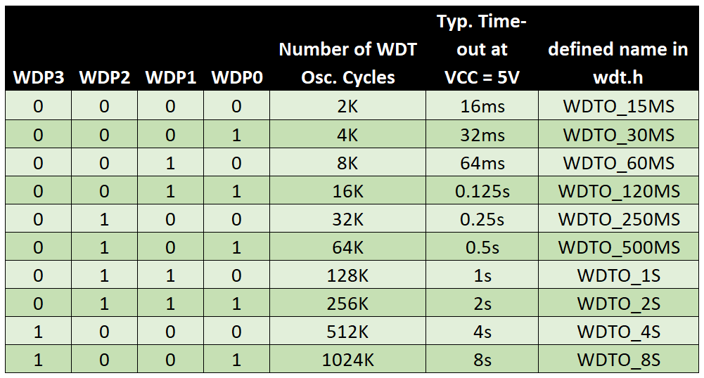
- WDPx: Watchdog Timer Prescaler – with these bits you set the period of the watchdog timer according to the following table.
- WDCE: Watchdog Change Enable – if you want to change the watchdog timer settings, then you first have to set this bit. The procedure will be explained further down below.
- WDE: Watchdog System Reset Enable – if you set this bit, a time-out of the watchdog timer triggers a reset of the microcontroller.
Setting up the watchdog timer – step-by-step instruction
We’re starting easy. The following sketch hangs in a while-loop because I have “forgotten” the incrementing of my counter i.
void setup(){
  Serial.begin(9600);
  Serial.println("Program with endless loop...");
  Serial.println("Sketch starts...");
}

void loop(){
  endlessLoop();
  Serial.println("I will never print this...");
}

void endlessLoop(){
  int i = 0;
  while(i < 5){
    //do nothing
  }
}
Watchdog Timer with system reset
Now a watchdog is to set up to get out of the endless loop and restart the microcontroller:
void setup(){
  Serial.begin(9600);
  Serial.println("Watchdog Timer Test");
  Serial.println("Sketch starts...");
  watchdogSetup();
}

void loop(){
  endlessLoop();
  Serial.println("I will never print this...");
  asm("WDR"); // this will not be executed
}

void watchdogSetup(void){
  cli(); // disable all interrupts
  asm("WDR"); // watchdog reset
  WDTCSR |= (1<<WDCE) | (1<<WDE);
  WDTCSR = (1<<WDE) | (1<<WDP3); // 4s / no interrupt, system reset
  sei();
}

void endlessLoop(){
  static int seconds = 0;
  int i = 0;
  while(i < 5){
    Serial.print(seconds);
    Serial.println(" Sekunden");
    delay(1000);
    seconds++;
  }
}
The setup of the watchdog timer is according to the following scheme:
cli()switches off all interrupts. This is necessary because the setup of the watchdog timer could be disruptedasm("WDR");is an assembler function for the watchdog reset; you will learn soon how to use a less cryptic function.WDTCSR |= (1<<WDCE) | (1<<WDE);initiates the change of the watchdog parameters. It is important to use “|=” and not “=”. After this initialization, the actual change must be made within the next 4 clock cycles.WDTCSR = (1<<WDE) | (1<<WDP3);means: Reset is enabled and the watchdog timer is set to four seconds (see settings table).sei();switches interrupts on again.
The watchdog reset at the end of the main loop (line 11) would prevent the system reset. However, this instruction will never be executed.
Here’s what the output looks like on the serial monitor:
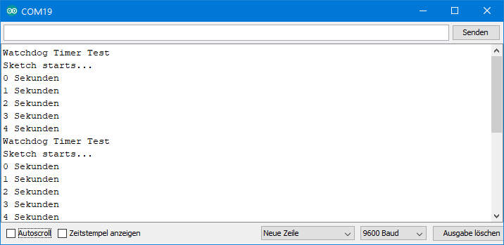
The watchdog works – the Arduino resets every four seconds. In theory, even the “4 seconds” should not be reached. However, the watchdog timer is less accurate than the other timers. Accordingly, the data sheet only specifies the time-out values as “typical”.
Watchdog timer with system reset and interrupt
The following sketch still contains the infinite loop that leads to the watchdog time-out. Here, the time-out not only leads to a reset, but before an interrupt is triggered. This in turn calls the ISR (Interrupt Service Routine). For this purpose, you must pass “WDT_vect” to the ISR.
void setup(){
  Serial.begin(9600);
  Serial.println("*******************");
  Serial.println("Watchdog Timer Test");
  Serial.println("Sketch starts...");
  watchdogSetup();
}

void loop(){
  endlessLoop();
  Serial.println("I will never print this...");
  asm("WDR"); // Watchdog Reset will not happen
}

void watchdogSetup(void){
  cli(); // disable all interrupts
  asm("WDR");
  WDTCSR |= (1<<WDCE) | (1<<WDE);
  WDTCSR = (1<<WDIE) | (1<<WDE) | (1<<WDP3); // 4s / interrupt, system reset
  sei();
}

void endlessLoop(){
  static int seconds = 0;
  int i = 0;
  while(i < 5){
    Serial.print(seconds);
    Serial.println(" Sekunden");
    delay(1000);
    seconds++;
  }
}

ISR(WDT_vect){
  Serial.println("....but I will print this before I reset soon");
}
Here’s what the output looks like:
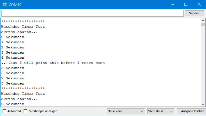
As you can see, the sketch continues for another four seconds before the reset is triggered. The interrupt grants a deferral of one watchdog period. When selecting the watchdog timer period, you must therefore make sure that the actions to be performed before the reset fit into one period.
Simplified notation with wdt.h
The cryptic setup of the watchdog timer can be made a little more pleasant by including the library “avr/wdt.h”:
- You don’t have to worry about turning off the interrupts by
cli();anymore. - Instead of
asm("WDR");you can usewdt_reset();. - The initialization by setting WDCE and the subsequent prescale setting is replaced by
wdt_enable(WDTO_XYZ);, whereby WDTO_XYZ is selected from table 1. - Strangely enough, no function is offered for activating the watchdog interrupt. To do this, you still need to use the binary operation
WDTCSR = (1<<WDIE);. - The watchdog interrupt without system reset cannot be set up with the wdt.h functions.
#include <avr/wdt.h>
void setup(){
  Serial.begin(9600);
  Serial.println("*******************");
  Serial.println("Watchdog Timer Test");
  Serial.println("Sketch starts...");
  watchdogSetup();
}

void loop(){
  endlessLoop();
  Serial.println("I will never print this...");
  wdt_reset(); // Watchdog Reset will not happen
}

void watchdogSetup(void){
  wdt_reset();
  wdt_enable(WDTO_4S); // 4s / System Reset
  WDTCSR = (1<<WDIE); // interrupt
}

void endlessLoop(){
  static int seconds = 0;
  int i = 0;
  while(i < 5){
    Serial.print(seconds);
    Serial.println(" Sekunden");
    delay(1000);
    seconds++;
  }
}

ISR(WDT_vect){
  Serial.println("....but I will print this before I reset");
}
An “OK” sketch
For the sake of completeness, here is a sketch with a loop that ends in time. To do this, I inserted i++ in line 30 and i<4 as a cancellation condition for the while loop.
#include <avr/wdt.h>
void setup(){
  Serial.begin(9600);
  Serial.println("*******************");
  Serial.println("Watchdog Timer Test");
  Serial.println("Sketch starts...");
  watchdogSetup();
}

void loop(){
  finiteLoop();
  Serial.println("Now I will print this...");
  wdt_reset();
}

void watchdogSetup(void){
  wdt_reset();
  wdt_enable(WDTO_4S);
  //wdt_enable(WDTO_2S);
  WDTCSR = (1<<WDIE);
}

void finiteLoop(){
  static int seconds = 0;
  int i = 0;
  while(i < 4){
    Serial.print(seconds);
    Serial.println(" Sekunden");
    delay(1000);
    i++;
    seconds++;
  }
}

ISR(WDT_vect){
  Serial.println("....but not this - as long there's no failure");
}
Here’s what the output looks like:
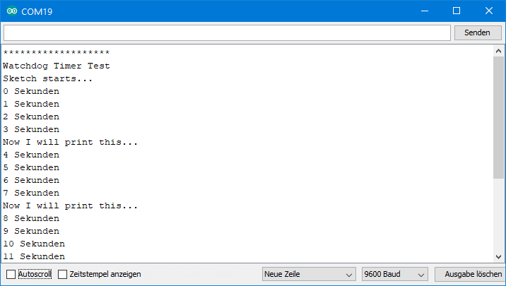
Try to comment line 18 and uncomment line 19 and see how the output changes.
Turning off the watchdog timer
If you have included avr/wdt.h, then you can simply turn off the watchdog timer using wdt_disable();. On a register level it looks like this:
void watchdogOff(){
  cli();
  asm("WDR");
  MCUSR &= ~(1<<WDRF);
  WDTCSR |= (1<<WDCE) | (1<<WDE);
  WDTCSR = 0x00;
  sei();
}
Perhaps you have noticed the instruction MCUSR &= ~(1<<WDRF);. MCUSR is the Microcontroller Status Register and WDRF is the Watchdog System Reset Flag bit. The latter overwrites the WDE bit in WDTCSR and therefore must be deleted first.
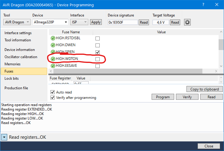
Watchdog timer “always on” with the Fuse Bit WDTON
If you have a program like Atmel (Microchip) Studio and a suitable programmer, you can also permanently activate the watchdog timer by setting the fuse bit WDTON. In this case, the reset mode is enabled without watchdog interrupt. So you can only modify the time-out.
Watchdog timer with interrupt and without reset
The variant with watchdog interrupt, but without system reset, cannot be realized in conjunction with wdt_enable();, as mentioned earlier. Therefore, you have to use the binary operations. Here’s an example:
#include <avr/wdt.h>

void setup(){
  Serial.begin(9600);
  watchdogSetup();
}

void loop(){
  Serial.println("Here's the loop!");
  delay(1000);
}

void watchdogSetup(void){
  cli();
  wdt_reset();
  WDTCSR |= (1<<WDCE) | (1<<WDE);
  WDTCSR = (1<<WDIE) | (1<<WDP3);  // 4s / interrupt, no system reset
  sei();
}

ISR(WDT_vect){
  Serial.println("Greetings from the ISR!");
}
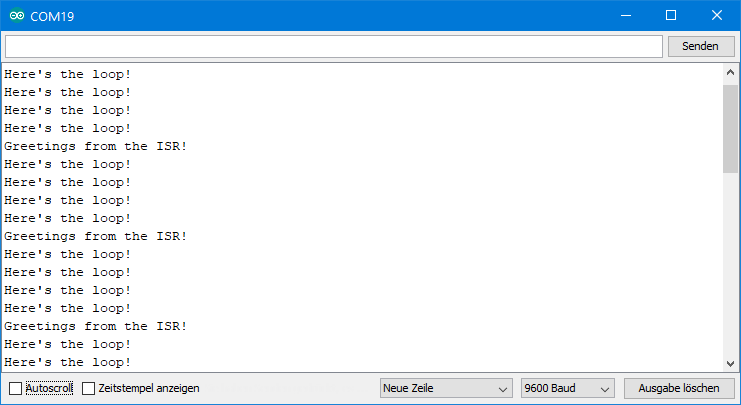
This setting of the watchdog timer is useful to let things be done periodically without having to consider time-dependent operations in the main loop. Perhaps a button is waiting to be pressed and a sensor needs to be read regularly. You could (mis-)use the watchdog interrupt to control the latter. Things like this can otherwise become complex.
Wake up with the watchdog timer
The watchdog timer can also be used to wake the microcontroller from sleep mode. One possible application would be, for example, to control a sensor that is supposed to perform a measurement every few seconds. If there is nothing to do in between, you can send the microcontroller to sleep to save battery power. This sketch shows how this works in principle:
#include <avr/wdt.h>
#include <avr/sleep.h>
const int ledPin = 12;

void setup(){
  pinMode(ledPin,OUTPUT);
  watchdogSetup();
}

void loop(){
  digitalWrite(ledPin,HIGH);
  delay(500);
  digitalWrite(ledPin,LOW);
  set_sleep_mode(SLEEP_MODE_PWR_DOWN); // chose power down modus
  sleep_mode(); // sleep now!
  sleep_disable(); // disable sleep after wake up
}

void watchdogSetup(void){
  cli();
  wdt_reset();
  WDTCSR |= (1<<WDCE) | (1<<WDE);
  WDTCSR = (1<<WDIE) | (0<<WDE) | (1<<WDP3) | (1<<WDP0);  // 8s / interrupt, no system reset
  sei();
}

ISR(WDT_vect){//put in additional code here
}
Longer than 8 seconds of sleep is not possible with this method. If necessary, however, you could install a counter that ensures that the desired action is only triggered after the umpteenth wake-up. Otherwise, it goes back to sleep.
Using watchdogs with the Arduino Pro Mini and Arduino Nano
The problem with the reset

The following sketch works well with the Arduino Uno without any problems. Every four seconds, the watchdog timer triggers a reset. If you try the same sketch on the Arduino Pro Mini or Arduino Nano, you will notice that the sketch only runs through once, and then it hangs.
#include <avr/wdt.h>
const int ledPin = 12;

void setup(){
  pinMode(ledPin,OUTPUT);
  watchdogSetup();
}

void loop(){
  digitalWrite(ledPin,HIGH);
  delay(1000);
  digitalWrite(ledPin,LOW);
  delay(500);
  endlessLoop();
  wdt_reset(); // will not happen
}

void watchdogSetup(void){
  cli(); // disable all interrupts
  wdt_reset();
  WDTCSR |= (1<<WDCE) | (1<<WDE);
  WDTCSR = (1<<WDE) | (1<<WDP3); // 4s / no interrupt, system reset
  sei();
}

void endlessLoop(){
  int i = 0;
  while(i < 5){
    delay(1000);
  }
}
A reset by the watchdog timer is not possible on the Arduino Pro Mini and it’s the same on the Arduino Nano. The problem is the bootloader. How to solve the problem by changing the bootloader is described here. But there are also two other simple alternatives, which I will describe below. Both are based on the watchdog being set with interrupt, but without reset. The reset is then done “manually” in the ISR.
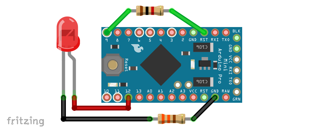
Workaround 1: Interrupt with hardware reset
A LOW signal on the reset pin of the Arduino Pro Mini initiates a hardware reset. You can use the following circuit and sketch:
#include <avr/wdt.h>
const int ledPin = 12;
const int resetPin = 9;

void setup(){
  pinMode(ledPin,OUTPUT);
  pinMode(resetPin,OUTPUT);
  digitalWrite(resetPin,HIGH);
  watchdogSetup();
}

void loop(){
  digitalWrite(ledPin,HIGH);
  delay(1000);
  digitalWrite(ledPin,LOW);
  delay(500);
  endlessLoop();
  wdt_reset(); // will not happen
}

void watchdogSetup(void){
  cli(); // disable all interrupts
  wdt_reset();
  WDTCSR |= (1<<WDCE) | (1<<WDE);
  WDTCSR = (1<<WDIE) | (0<<WDE) | (1<<WDP3); // 4s / no interrupt, system reset
  sei();
}

void hardwareReset(){
  digitalWrite(resetPin,LOW);
}

void endlessLoop(){
  int i = 0;
  while(i < 5){
    delay(1000);
  }
}

ISR(WDT_vect){
  hardwareReset();
}
If you swap lines 7 and line 8 in the sketch, you can do without the 1 kOhm resistor between pin 9 and RESET. Without swapping, the short time in which pin 9 is on OUTPUT and not yet HIGH is out is enough to give a reset signal.
Workaround 2: Interrupt with software reset
For the second workaround, replace the hardwareReset() function with a software reset function: void (*resetFunc)() = 0. Then you call the function resetFunc(); in the ISR. Or you just write directly to the ISR: asm volatile ("jmp 0");. No further wiring is necessary for this.
The disadvantage of this method, however, is that there is no real reboot, but only a program restart. The microcontroller jumps to the address zero. All register contents, pin statuses, etc. are preserved as they are and can thus cause undesirable effects. So if necessary, you need to add a function to the setup that ensures a safe initial state.
The watchdog at ESP8266

Compared to the AVR microcontrollers, the watchdog timer of the ESP8266 is basically designed differently. First of all, it has a hardware and a software watchdog timer. The software watchdog timer is automatically activated without any further intervention. Upload the following sketch on your ESP8266 and see what’s happening on the serial monitor (set 115200 Baud!)
void setup() {
  //ESP.wdtDisable();
}

void loop() {
  while(1){}
}
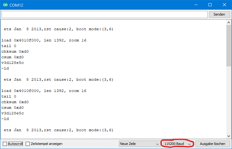
As you can see, the ESP8266 restarts approximately every three seconds. Figuratively speaking, the software watchdog “feeds” the hardware watchdog so that it doesn’t “bite.” To turn off the software watchdog, uncomment the function ESP.wdDisable(); and see what happens:
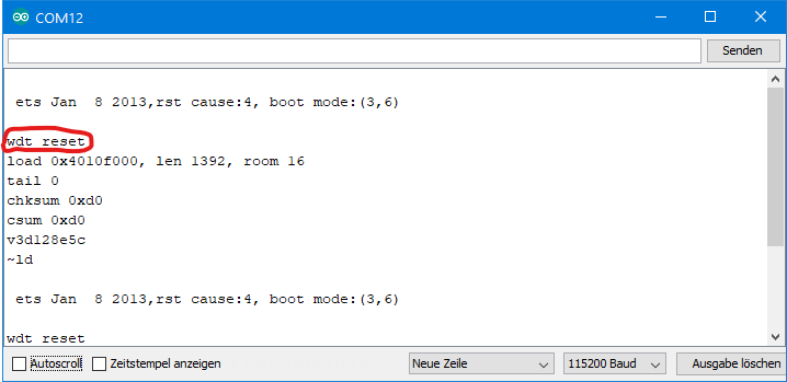
Now there is a reset about every eight seconds and “wdt reset” appears on the serial monitor. That was the hardware watchdog. To prevent the watchdog from biting, you can feed it by inserting ESP.wdtFeed(); into the while loop. However, you might as well insert delay(x ms); or any other function.
Limited settings
There are virtually no ways to configure hardware and software watchdog timers on the ESP8266. Basically, you can only choose between the two watchdog variants. If you have turned off the software watchdog, you can activate it with ESP.wdtEnable(x); again. x is an integer value that must be passed to the function. This raises the hope that it could be used to control the time-out period. Unfortunately, that is not the case. It doesn’t matter if you choose e.g. ESP.wdtEnable(0); or ESP.wdtEnable(4000); or ESP.wdtEnable(WDTO_4S);, the effect is always the same.
Create a more convenient watchdog timer yourself
If you need a watchdog timer that has similar functions to the AVR Watchdog Timer, you can create it yourself using the library Ticker.h with a few lines of code.Here you find an example.
Acknowledgement
The watchdog in the post picture I got from Manfred Richter on Pixabay, the stopwatch comes from OpenClipart-Vectors, also Pixabay.
Exclusive thanks to you, today i have learned a lot about guard dogs. I think i will place one to one of my future fences.
You content is always outstanding excellent and immediately becomes one of my favorite electronics knowledge base sources. Thank you!
I agree with Jean Louis, very helpfull, thank you. I am working with the Arduino pro-mini and I found a solution that at least works for me. I disable the watchdog before jumping:
…
wdt_disable();
asm volatile (“jmp 0”);
Merci!
Thanks a lot,
Several examples with erroneous sequences are proposed on several sites. Your explanation of how the watchdog timer works is by far the best.
Many thanks – this is very motivating for me! Greetings to France!