About the post
Hall sensors and reed switches are electronic components that respond to magnetic fields. They work very differently, but are used for the same purpose, namely to control circuits or mechanical devices using magnets. That is why I deal with them together in a single post. This is what I am going to handle:
- Functional principle of hall sensors
- Digital Hall sensors
- Linear Hall sensors
- Hall sensor modules
- Hall sensor on the ESP32
- Functional principle of reed switches
- Reed switch based bicycle speedometer
Hall sensors
Principle
When an electric current flows through a magnetic field, an electric voltage is generated that is perpendicular to the current flow and the magnetic field. This effect was detected by the physicist Edwin Hall and is therefore called the Hall effect. The reason for this effect is the Lorentz force, which you may still know from physics lessons (three-finger rule). This is explained here very simply and with beautiful drawings.
The Hall effect is small. Hall sensors have therefore integrated amplifier circuits. Linear Hall sensors and Hall sensors with digital output are distinguished. If nothing else is specified, then Hall sensors usually mean the digital representatives.
Digital Hall sensors
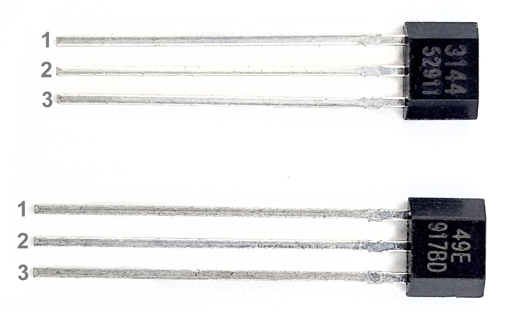
A widely used digital Hall sensor is the 3144. You can get the 3144 under this name or as 3144E or A3144E or similar for little money on Amazon, eBay and Co.
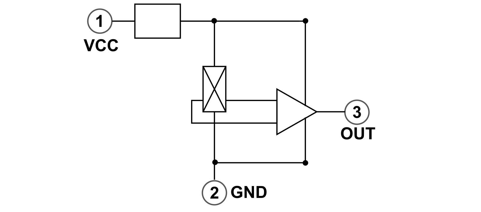
The 3144 has three pins: VCC, GND and OUT. Its supply voltage should be between 4.5 and 24 volts. The power consumption of the 3144 is a few milliamps. The block diagram looks like this:
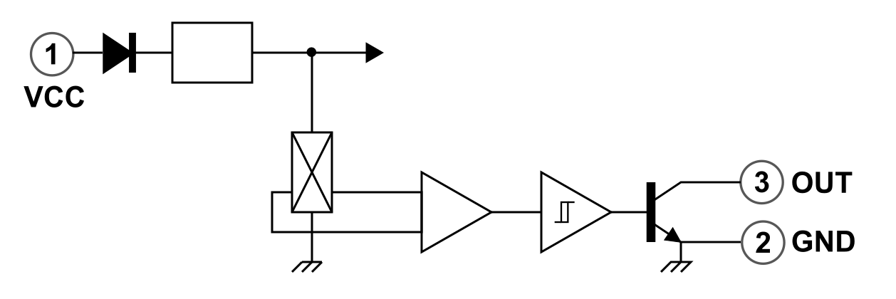
The crucial point is that the transistor switches between OUT and GND when the magnetic field acting on the 3144 exceeds a certain limit. However, it should also be noted that the effect of the magnetic field depends on how the field lines are oriented relative to the 3144. You can test this with the following simple circuit:
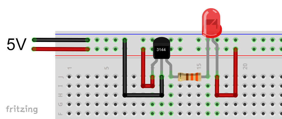
If you bring a magnet near the 3144 Hall sensor, you will notice that the LED only lights up when you approach one of the two poles. The other is seemingly ineffective. If you take the ineffective pole, but approach the 3144 from the other side, the LED lights up again.
The distance at which the LED lights up depends, of course, on the strength of the magnet. Usually, that’s a few centimeters. You must not attach more than one LED to the 3144. 25 milliamperes is the maximum current that can flow through OUT as a sink.Using the 3144 on the Arduino
On the Arduino you can use the 3144 e.g. with the following circuit:

Here’s the sketch:
const int hallPin = A0;
int hallSignal = 0;
void setup(){
  Serial.begin(9600);
}

void loop(){
  hallSignal = analogRead(hallPin);
  Serial.println(hallSignal);
  delay(1000);
}
And this is what the output looks like when approaching with the “right” side of the magnet:
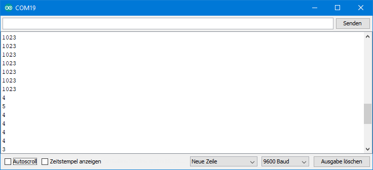
I chose to use the function analogRead only for didactic reasons to demonstrate the sharp transition from HIGH to LOW. In practice, of course, you should choose the faster digitalRead method. Or you can directly access the port input pin register, as I have described it here.
Other digital Hall sensors
I have chosen 3144 as an example, as it is very widespread. It still has “siblings”, namely 3141, 3142 and 3143. These differ mainly in the magnetic field strength at which they switch. The 314x family are unipolar Hall sensorsbecause they detect only one pole of the magnetic field. In addition, there are bipolar Hall sensorsthat react to both magnetic poles.
The 3144 is not only a unipolar Hall sensor, but also a non-latching Hall sensor. And if there are non-latching Hall sensors, then of course there arealso latching Hall sensors. The latter switch as usual at a certain magnetic field strength, but then need an opposite magnetic field to change the state again.
Linear Hall sensors
Linear Hall sensors differ from the digital representatives in that they do not switch abruptly. Rather, they provide a voltage of OUT that is proportional to the magnetic field strength. Here is the block diagram:
A widely used linear Hall sensor is the 49E. You can get the 49E under this designation or similar (SS49E, AH49E) for little money on Amazon, eBay and Co. The supply voltage is usually given as 3 – 6.5 volts. The current consumption is a few milliamperes.
Using the 49E at the Arduino
Without a magnetic field, the voltage at OUT is about half the input voltage. You can read this with the same sketch as above. The “circuit” is even simpler:

Now, when you approach a magnet to the Linear Hall sensor, you can see how the voltage changes at OUT. Whether it rises or falls depends on how the magnetic field is directed towards the Hall sensor. In other words, it depends on whether you approach with the north or south pole and at what angle the magnetic field lines meet the Hall sensor. Accordingly, the result on approximation can look like this:
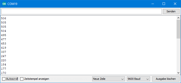
Or like this, if the magnetic field is reversed:

Alternatively, you can put an LED between OUT and GND and watch how the LED becomes lighter or darker depending on the magnetic field. It should only be noted that the 49E delivers a maximum of 10 milliamperes to OUT.
Again, the distance at which a voltage change occurs depends, of course, on the strength of the magnet. But typically the range is a few centimeters, no more. The voltage changes linearly with magnetic field strength as long as you do not change the orientation of the 49E toward the magnet.
And now you can let your imagination run wild as you want to use the linear Hall sensor. In the simplest case you just use it as a proximity switch. In practice, however, the linear Hall sensors are more likely to be used for positioning tasks of all kinds. A short article can be found here.
Hall sensor modules

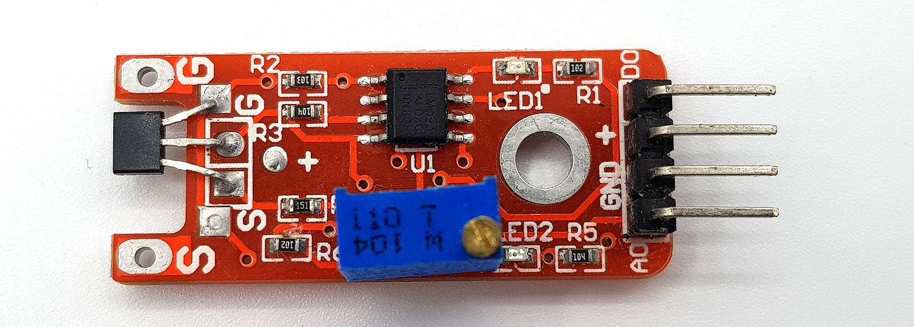
You can also get Hall sensors as modules, but most of them don’t really offer any real advantages. They also take up more space than necessary. The modules of the 44E and the 3144 shown above have a small LED that lights up when the sensor switches. The 49E module has no additional features.
The 49E module shown below has not only the analog but also a digital output. The point, i.e. the magnetic field strength at which the digital output switches, can be adjusted via the potentiometer. This version therefore provides a certain added value.
The ESP32’s integrated Hall sensor
UPDATE: Sorry, support of the hall sensor of the ESP32 has ended – what a pity!

Some of you may have worked with the ESP32 board before. This has an integrated linear Hall sensor located under the cover. If you have integrated the board into the Arduino IDE, you can simply read the Hall sensor using the hallRead() function. Without a magnetic field, the function returns values around zero. In the magnetic field, the function provides larger positive or negative values depending on the orientation of the magnetic field. With a strong magnet, I have reached value up to +/- 140. It is less nice that the values vary comparatively strongly regardless of the magnetic field strength (by +/-5 and above). For more accurate measurements, I would therefore use the Hall sensors described above.

Reed switches
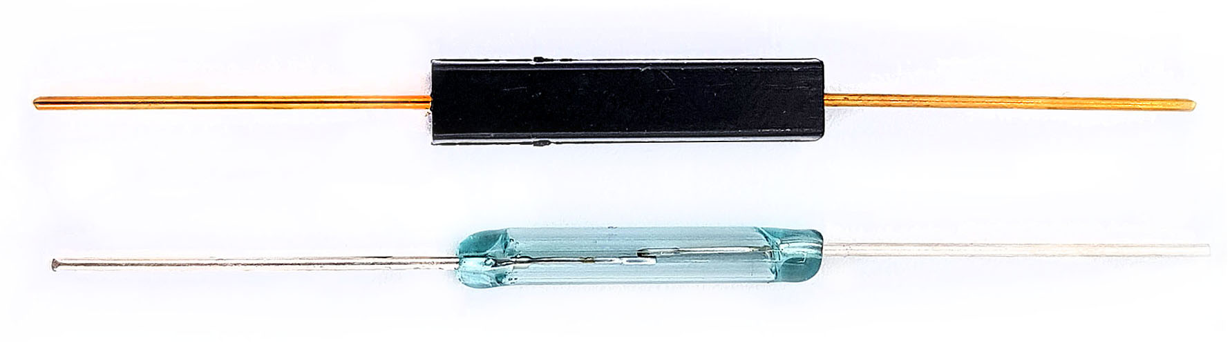
Reed switches consist of two overlapping metal contact leads (reeds) that are melted into a glass tube. There is a narrow gap between the contact leads. Under the influence of a magnetic field of sufficient strength and in the axial direction, the contact leads overcome the spring tension and touch each other. This closes the contact. Outside the magnetic field, the contact reopens.
The glass tubes are quite vulnerable to shocks. Alternatively, reed switches with plastic sleeves are available (as shown above).
For most reed switches, the maximum switching current is 0.5 and the maximum continuous current is 1 ampere. The maximum switching voltage is usually given as 100 volts DC.
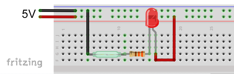
For example, a very simple test circuit can look like this:
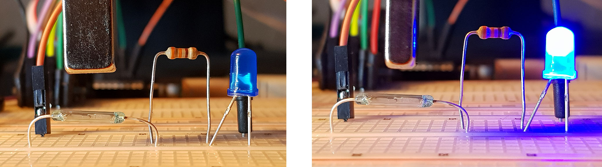
The next two images demonstrate once again that the orientation of the magnetic field is crucial. I should mention that the magnet used has its north and south pole on the flat sides. So unlike a classic rod magnet.
Using the reed switch at the Arduino
At the Arduino you can separate the reed switch signal and the associated action (here: switch LED):

Here’s what a sketch might look like:
const int reedPin = 8;
const int ledPin = 12;
void setup(){
  pinMode(ledPin, OUTPUT);
}

void loop(){
 if(!digitalRead(reedPin)){
   digitalWrite(ledPin, HIGH);
 }
 else{
   digitalWrite(ledPin,LOW);
 }
}
Bicycle speedometer with reed switch build
I didn’t really build a bicycle speedometer, I just want to show how it works in principle. For this purpose I attached a magnet to a tire and placed it opposite a reed switch that was attached to a photo tripod. The circuit is the same as above.

The simple sketch looks like this:
int tachoPin = 8;
int ledPin = 12;
void setup(){
  pinMode(ledPin, OUTPUT);
}

void loop(){
 if(!digitalRead(tachoPin)){
   while(!digitalRead(tachoPin));
   digitalWrite(ledPin, HIGH);
   delay(200);
   digitalWrite(ledPin,LOW);
 }
}
Here’s what it looks like in action:
Reed switch based bicycle speedometer – the principleTo make a bike speedometer out of it, you only have to divide the wheel circumference by the time between the switching events and convert it into kilometers per hour.
Addendum: A reader has actually recreated a bike speedometer and found that his reed switch also switched under the influence of strong vibrations or shocks. Shock-resistant reed switches thus seem to be the special know-how of the speedometer manufacturers. I cut open a sensor to see what’s really in it. This is not so easy because everything is poured in plastic, but you can recognize the reed switch quite well:

What also suggests that it is a reed switch and not a Hall sensor is, on the one hand, the fact that the sensor is only connected to two lines. On the other hand, when aligning the magnet attached to the spokes with the sensor, a permanent contact is created. You can check this non-destructively if check the contacts of the holder (top of the handlebars) with a multimeter.
Acknowledgement
I have composed the post image from three pictures or parts of the picture. All found on Pixabay.
- the Arduino is from Seven_au
- I owe the magnets to Clker-Free-Vector-Images
- the screws, gears, etc. come from Annalise Batista