About this Post
After I reported in my last post about the real-time clock module DS3231, a follow-up article about DCF77 radio clocks fits very well thematically.
I will deal with the following points:
- What is the DCF77 time signal?
- Decoding of the DCF77 signal.
- DCF77 Receiver Modules
- Detection and evaluation of the DCF77 signal with the Arduino.
- Using the DCF77 receiver comfortably with the RTCLib.
The DCF77 time signal
DCF77 is a time signal used to transmit the current date and time digitally on the long wave frequency 77.5 kHz. The time zone is CET (Central European Time) or the CEST (Central European Summer Time).
The DCF77 transmitter is located in Mainflingen near Frankfurt in Germany. Here you can admire it on Google Maps. It has a range of about 2000 kilometers and controls a large part of the radio clocks in Western Europe. Other parts of the world have time signals that use different frequencies and are also encoded differently.
DCF77 means:
- D: Germany
- C: Abbreviation for long wave
- F: Proximity to Frankfurt
- 77: Transmission frequency
More information about the DCF77 signal and its history can be found here.
How the DCF77 signal is structured
The information is transmitted by reducing the amplitude of the carrier to 25 percent once per second for either 100 or 200 milliseconds. A reduction for 100 milliseconds corresponds to a “0”, 200 milliseconds corresponds to a “1”. A full sequence is one minute. This would transfer 60 bits, but the last bit is omitted to clearly separate the sequences.
Most DCF77 receiver modules are designed to deliver a HIGH signal while the time signal is reduced, otherwise it is LOW. This will give you sequences that look like the following:
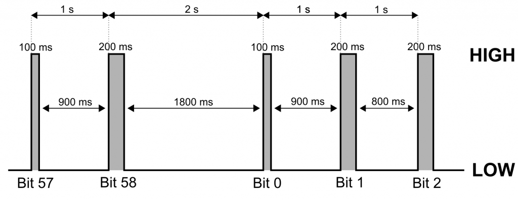
If you have a module that works the other way around, you need to rethink and modify the example sketches accordingly.
Decoding the DCF77 signal
Certain bits or sections are reserved for a specific part of the information to be transmitted:
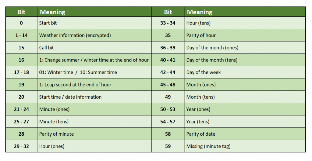
- To read the weather information, you would need to purchase a license.
- The actual transmission of the time and date begins after bit 20. I don’t look at anything before that.
- For two-digit numbers, the “ones” and the “tens” are transmitted separately, but each digit is transmitted as a binary number – a somewhat strange mixture of binary and decimal systems.
- The times coded in a sequence refer to the next start bit.
The parity bits can be used to check the transmitted data for correctness. The parity of the parity bit plus the parity of the corresponding data is always even. This can best be explained with an example. The minutes are coded in the bits 21 to 27, i.e. 7 zeros or ones. All ones are added. If the result is an odd number, the parity bit is an odd 1. If, on the other hand, the result is an even number, the parity bit is 0. The same applies to the hours (bits 29-34) and the date (bits 40-57). In other words, the parity of the parity bit equals the parity of the bit sequence to be checked.
If all parities are OK and you have received 59 bits in a sequence, you can be quite sure that the data transfer was correct.
Here you can follow live what the DCF77 transmitter is currently transmitting.
DCF77 Receiver Modules
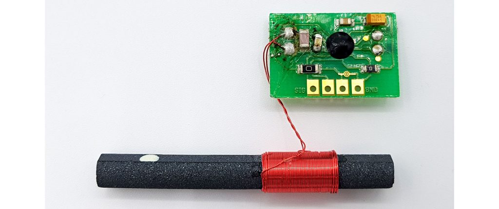
You can get a module with antenna for 5 to 15 euros in online shops. I paid 11 euros for the model shown here and am quite satisfied with its reception quality:
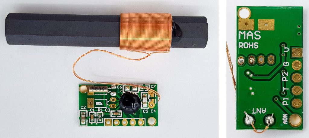
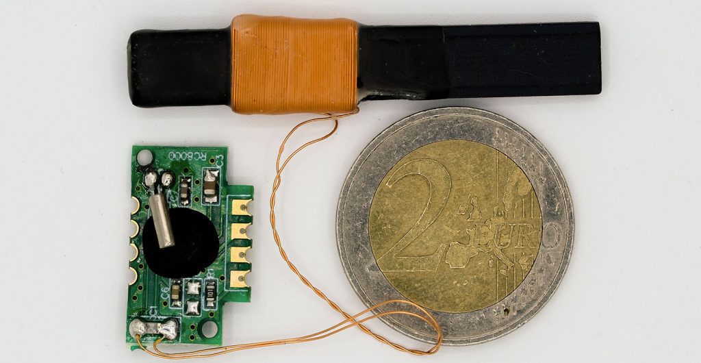
This model here cost only half and is much smaller:
There was no documentation for it (not even regarding the supply voltage!), and I also got significantly more incorrect measurements with it than with the other module under the same conditions. So there are clear differences in quality here.
However, invalid sequences are not only a question of module quality, but also the orientation of the antenna, the weather, the location (geology) and other factors can influence the reception. However, a few incorrect measurements are not a problem as long as you identify them and your code is not dependent on receiving a valid data set every minute. If you experience too many incorrect sequences, try to position the antenna differently. What can also help with some modules is battery operation.
“RC8000” modules
Then there are the DCF-1060N-800 and DCF-3850M-800 modules, whose circuit board is labeled “RC8000”. I have had wonderful experiences with these, especially with the DCF-3850M-800, which is also characterized by a small antenna. There were hardly any incorrect measurements, regardless of the positioning of the antenna. According to the seller, the DCF-1060N-800 has a slightly higher sensitivity, but I cannot confirm this. The DCF-3850M-800 module can be found in many radio-controlled alarm clocks (thanks, Claus!).
If you want to buy a module, it is best to see if there is a data sheet or at least basic technical data for it. Some representatives can apparently only tolerate up to 3.3 V, others up to 5 V or even more. For the power consumption, I have found consistent data of < 100 microamperes.
The Canaduino Board
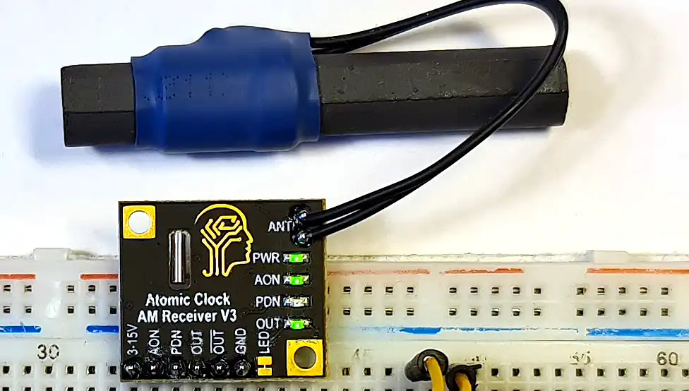
In my experience, the technically best module is the Canaduino model shown above (the DCF-3850M-800/RC8000 module wins the “size prize”, however). I paid 20 euros for it, including shipping costs from Canada. You can operate it with 3 -15 volts, it has automatic amplification and has a regular and an inverted output. The quality of the signals was excellent, even in places where other modules had difficulties. A short manual for the module is available here.
Please pay particular attention to the alignment of the antenna relative to the module. For fast signal acquisition, connect PDN to a pin on your microcontroller board and switch it to Output / LOW in setup().
Receiving and evaluating the DCF77 signal
Wiring
As already mentioned, the modules vary in their design. For the module shown above I used the following wiring:
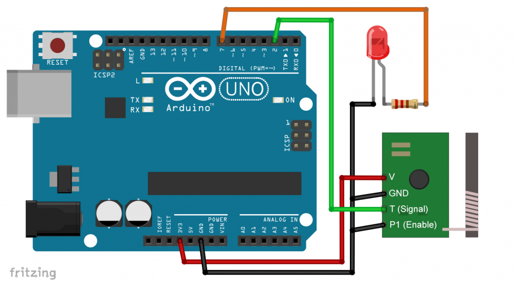
- The LED is not essential, I use it for some example sketches.
- The Enable Pin can be used to turn the module on and off (not every module has this feature).
- For most of my sketches, the signal pin must be connected to an interrupt pin.
A simple function test
If you just want to check if your module receives data at all, you can use this sketch:
int interruptPin=2;
int ledPin=7;

void setup(){
  pinMode(ledPin, OUTPUT);
  pinMode(interruptPin, INPUT);
  attachInterrupt(digitalPinToInterrupt(interruptPin), DCF77_ISR, CHANGE);
}

void loop(){

}

void DCF77_ISR(){
  if(digitalRead(interruptPin)){
    digitalWrite(ledPin, HIGH);
  }
  else{
    digitalWrite(ledPin, LOW);
  }
}
Alternatively, it would work without interrupt, for example like this:
int dataPin = 2;
int ledPin = 7;

void setup() {
  pinMode(dataPin, INPUT);
  pinMode(ledPin, OUTPUT);
}

void loop() {
  if(digitalRead(dataPin)){
    digitalWrite(ledPin, HIGH);
  }
  else{
    digitalWrite(ledPin, LOW);
  }
}
The interrupt method has the advantage that the main loop is empty, so you can do anything else in parallel. I will therefore build on the interrupt method.
When the sketch is running, the LED should flash every second. If you look closely, you will notice that the LED lights up shorter times and sometimes longer. Once per minute, the pause is almost two seconds. Interference with reception is usually noticeable by rapid and irregular flashing.
How to capture sequences
With the next sketch, we measure the signal lengths and capture entire sequences. A few comments on the signal length:
- After the interrupt is triggered, it is checked whether the interrupt pin is HIGH or LOW. This reveals whether the completed phase is the 100/200 millisecond signal or the pause.
- The signal length is determined by the
millis()function. - All HIGH signals shorter than 150 milliseconds are interpreted as “0”, the longer ones as “1”. The optimum value may differ for some module/board combinations.
- A LOW phase greater than 1500 milliseconds indicates the minute tag.
Another few comments on the sequence:
- The 59 bits of a sequence fit into an eight-byte
uint64_tvariable (= unsigned long long on an AVR Arduino), which I have named currentBuf. - The counter for the position in currentBuf is bufCounter.
currentBuf |= ((uint64_t)1<<bufCounter);inserts a “1” into the sequence. Without the conversion of the “1” touint64_t, it will not work. It took me a long time to come to this realization.- The
Serial.print()function is not compatible withuint64_tvariables. I use bit operations to divide the currentBuf variable into twouint32_tpieces to be able to output them. - The sequence is output when the minute tag is detected.
At 9600 BAUD, the Serial.print() calls take a total time in the millisecond range (per second). That’s why I chose 115200 BAUD.
The sequence ends with the long LOW pause after the 59th HIGH signal (= no. 58). This is followed by the start bit of the next sequence. We use these 100 milliseconds for evaluation and output.
#define MIN_HIGH_SIGNAL 150 // min. high signal - test and adust
#define MIN_END_SIGNAL 1500 // min. low phase after 59th signal
int interruptPin = 2;
unsigned int bufCounter = 0;
volatile unsigned long lastInt = 0;
volatile uint64_t currentBuf = 0;
volatile bool newSignal = false;
volatile bool newSequence = false;
volatile unsigned long highDur = 0;
volatile unsigned long lowDur = 0;

void setup() {
  Serial.begin(115200);
  Serial.println(" HIGH  /  LOW");
  pinMode(interruptPin, INPUT);
  attachInterrupt(digitalPinToInterrupt(interruptPin), DCF77_ISR, CHANGE);
}

void loop() {
  if(newSignal) {
    newSignal = false;
    Serial.print(bufCounter);
    Serial.print(". ");
    Serial.print(highDur);
    Serial.print("  /  ");
    Serial.println(lowDur);
    bufCounter++;

    if (newSequence) {
      uint32_t highBuf = (currentBuf>>32) & 0x7FFFFFF;
      uint32_t lowBuf = (currentBuf & 0xFFFFFFFF);
      newSequence = false;
      newSignal = false;
      bufCounter = 0;
      Serial.print("Signal, upper 4 bytes: ");
      Serial.println(highBuf, BIN);
      Serial.print("Signal, lower 4 bytes: ");
      Serial.println(lowBuf, BIN);
    }
  }
}

void DCF77_ISR() {
  unsigned int dur = 0;
  dur = millis() - lastInt;

  if(digitalRead(interruptPin)){
    lowDur = dur;
    newSignal = true;

    if(dur > MIN_END_SIGNAL) {
      newSequence = true;
    }
  }
  else{
    highDur = dur;

    if(dur > MIN_HIGH_SIGNAL) {
      currentBuf |= ((uint64_t)1<<bufCounter);
    }
  }
  lastInt = millis();
}
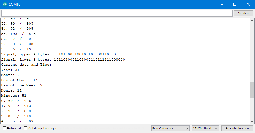
Output of dcf77_get_sequence.ino
Here you can see a snapshot of the output:

The HIGH and LOW phases differ a little from the ideal lengths, but zeros and ones are clearly distinguishable.
The first recorded sequence will only be a complete one in 2 out of 60 cases, namely when you in the last two seconds of a running sequence.
Evaluating the captured sequences
Now let’s evaluate the received sequences. To do this, the ISR passes the currentBuf sequence to the evaluateSequence() function. This first splits the sequence into the relevant sections (minute, hour, day of the week, etc.).
For the parity check, I use the function parity_even_bit() . To use it, you need to include utils/parity.h. This file is part of the Arduino or AVR standard package, so you don’t have to install it. parity_even_bit() expects a byte value as an argument. The function returns “0” (false) for parity “0” and “1” for parity “1”. The date piece is greater than one byte, so I’ll check the parities of the calendar day, day of the week, month, and year individually. If the sum of the parities is an even number, then the total parity is 0. If it is odd, the parity is “1”. If you are not using an AVR board (Arduino UNO, Nano, Mega, etc.), do not include parity.h and uncomment the replacement function at the end of this and the following sketches.
rawByteToInt() splits the raw value of minute, hour, day, etc. into the digits and returns the sum as an integer. These values are then output.
#include <util/parity.h> //comment out if you don't use an AVR MCU
#define MIN_HIGH_SIGNAL 150
#define MIN_END_SIGNAL 1500
int interruptPin=2;
unsigned int bufCounter;
volatile unsigned long lastInterrupt = 0;
uint64_t tempBuf = 0;
volatile uint64_t currentBuf = 0;
volatile bool newSignal = false;
volatile bool newSequence = false;
volatile unsigned long highDur = 0;
volatile unsigned long lowDur = 0;

void setup() {
  Serial.begin(115200);
  Serial.println(" HIGH  /  LOW");
  pinMode(interruptPin, INPUT);
  attachInterrupt(digitalPinToInterrupt(interruptPin), DCF77_ISR, CHANGE);
}

void loop(){
  if(newSignal) {
    newSignal = false;
    Serial.print(bufCounter);
    Serial.print(". ");
    Serial.print(highDur);
    Serial.print("  /  ");
    Serial.println(lowDur);
    bufCounter++;

    if (newSequence) {
      uint32_t highBuf = (currentBuf>>32) & 0x7FFFFFF;
      uint32_t lowBuf = (currentBuf & 0xFFFFFFFF);
      newSequence = false;
      tempBuf = currentBuf;
      while(digitalRead(interruptPin)) {;} // we wait for the first Low
      currentBuf = 0;
      bufCounter = 0;
      newSignal = false;
      Serial.print("Signal, upper 4 bytes: ");
      Serial.println(highBuf, BIN);
      Serial.print("Signal, lower 4 bytes: ");
      Serial.println(lowBuf, BIN);
      evaluateSequence();
    }
  }
}

void evaluateSequence(){
  uint8_t dcf77Year = (tempBuf>>50) & 0xFF;    // year = bit 50-57
  uint8_t dcf77Month = (tempBuf>>45) & 0x1F;       // month = bit 45-49
  uint8_t dcf77DayOfWeek = (tempBuf>>42) & 0x07;   // day of the week = bit 42-44
  uint8_t dcf77DayOfMonth = (tempBuf>>36) & 0x3F;  // day of the month = bit 36-41
  uint8_t dcf77Hour = (tempBuf>>29) & 0x3F;       // hour = bit 29-34
  uint8_t dcf77Minute = (tempBuf>>21) & 0x7F;     // minute = 21-27
  bool parityBitMinute = (tempBuf>>28) & 1;
  bool parityBitHour = (tempBuf>>35) & 1;
  bool parityBitDate = (tempBuf>>58) & 1;

  if((parity_even_bit(dcf77Minute)) != parityBitMinute){
    Serial.println("Minute parity not OK");
  }

  if((parity_even_bit(dcf77Hour)) != parityBitHour){
    Serial.println("Hour parity not OK");
  }

  if(((parity_even_bit(dcf77DayOfMonth) + parity_even_bit(dcf77DayOfWeek)
  + parity_even_bit(dcf77Month) + parity_even_bit(dcf77Year))%2) != parityBitDate)
  {
    Serial.println("Date parity not OK");
  }

  Serial.println("Current date and Time:");
  Serial.print("Year: "); Serial.println(rawByteToInt(dcf77Year));
  Serial.print("Month: "); Serial.println(rawByteToInt(dcf77Month));
  Serial.print("Day of Month: "); Serial.println(rawByteToInt(dcf77DayOfMonth));
  Serial.print("Day of the Week: "); Serial.println(rawByteToInt(dcf77DayOfWeek));
  Serial.print("Hours: "); Serial.println(rawByteToInt(dcf77Hour));
  Serial.print("Minutes: "); Serial.println(rawByteToInt(dcf77Minute));
}

unsigned int rawByteToInt(uint8_t raw){
  return ((raw>>4)*10 + (raw &0x0F));
}

void DCF77_ISR(){
  unsigned int dur = 0;
  dur = millis() - lastInterrupt;
  lastInterrupt = millis();

  if(digitalRead(interruptPin)){
    lowDur = dur;
    newSignal = true;

    if(dur > MIN_END_SIGNAL) {
      newSequence = true;
    }
  }
  else{
    highDur = dur;

    if(dur > MIN_HIGH_SIGNAL){
      currentBuf |= ((uint64_t)1<<bufCounter);
    }
  }
}

//uncomment the following lines if you don't use an AVR MCU
//bool parity_even_bit(uint8_t val){
//  val ^= val >> 4;
//  val ^= val >> 2;
//  val ^= val >> 1;
//  val &= 0x01;
//  return val;
//}
Output of dcf77_sequence_evaluation.ino
So it’s Sunday, February 14, 2021, 12:59. It works, but the formatting still leaves opportunities for improvement.
For example, the names for the months or days of the week could be inserted as:
char dayName[7][12] = {"Sunday", "Monday", "Tuesday", "Wednesday", "Thursday", "Friday", "Saturday"};
Serial.print(dayName[dcf77DayOfWeek]);
But I’m going down a different, much more comfortable path.
Using the DCF77 with the RTCLib
I introduced the RTCLib in the last post as a library for the DS3231 real-time clock module. In addition to this task, the RTCLib also offers (among other things):
- A wide range of formatting options for date and time.
- Calculation operations with date/time and time periods.
- Software simulation of a real-time clock (SoftRTC).
I had presented all this in my last post. If you don’t understand the next sketch, it’s best to go back there.
You can download the RTCLib via the Arduino IDE or directly from GitHub here.
We use SoftRTC and set this “software watch” regularly with the DCF77 receiver. In between, the clock runs based on millis().
Of course, you can use the DCF77 receive to set a DS3231 module as well.
DCF77 and SoftRTC – the sketch
I freed the code used in the last sketch from all non-essential Serial.print() parts. Then I combined it with the example sketch softrtc.ino of the RTCLib and adapted it somewhat.
The clock is initially set to 1/1/2000, 00:00. You could also use the computer’s system time, but I wanted an obviously wrong start date to make it clearer when the clock is set by the DCF77 module.
The clock is only set if there is a valid record, i.e. if 59 bits have been submitted and the three parity bits are correct.
#include <util/parity.h> //comment out if you don't use an AVR MCU
#include "RTClib.h"
#define MIN_HIGH_SIGNAL 150
#define MIN_END_SIGNAL 1500

int interruptPin = 2;
volatile unsigned long lastInterrupt = 0;
volatile uint64_t currentBuf = 0;
volatile unsigned int bufCounter;

RTC_Millis rtc;

void setup() {
  rtc.adjust(DateTime(2000, 1, 1, 0, 0, 0));
  Serial.begin(115200);
  pinMode(interruptPin, INPUT);
  attachInterrupt(digitalPinToInterrupt(interruptPin), DCF77_ISR, CHANGE);
}

void loop(){
  static DateTime now = rtc.now();
  now = rtc.now();
  char buf1[] = "Today is DDD, MMM DD YYYY";
  Serial.println(now.toString(buf1));
  char buf2[] = "Current time is hh:mm:ss";
  Serial.println(now.toString(buf2));
  Serial.println();

  delay(3000);
}

void DCF77_ISR() {
  unsigned int dur = 0;
  dur = millis() - lastInterrupt;
  lastInterrupt = millis();

  if(digitalRead(interruptPin)) {

    if(dur > MIN_END_SIGNAL) {

      if(bufCounter==59) {
        evaluateSequence();
      }
      bufCounter = 0;
      currentBuf = 0;
    }
  }
  else{
    if(dur > MIN_HIGH_SIGNAL) {
      currentBuf |= ((uint64_t)1<<bufCounter);
    }
    bufCounter++;
  }
}

void evaluateSequence(){
  uint8_t dcf77Year = (currentBuf>>50) & 0xFF;    // year = bit 50-57
  uint8_t dcf77Month = (currentBuf>>45) & 0x1F;       // month = bit 45-49
  uint8_t dcf77DayOfWeek = (currentBuf>>42) & 0x07;   // day of the week = bit 42-44
  uint8_t dcf77DayOfMonth = (currentBuf>>36) & 0x3F;  // day of the month = bit 36-41
  uint8_t dcf77Hour = (currentBuf>>29) & 0x3F;       // hour = bit 29-34
  uint8_t dcf77Minute = (currentBuf>>21) & 0x7F;     // minute = 21-27
  bool parityBitMinute = (currentBuf>>28) & 1;
  bool parityBitHour = (currentBuf>>35) & 1;
  bool parityBitDate = (currentBuf>>58) & 1;

  if((parity_even_bit(dcf77Minute)) == parityBitMinute){

    if((parity_even_bit(dcf77Hour)) == parityBitHour){

      if(((parity_even_bit(dcf77DayOfMonth) + parity_even_bit(dcf77DayOfWeek)
           + parity_even_bit(dcf77Month) + parity_even_bit(dcf77Year))%2) == parityBitDate){
        rtc.adjust(DateTime(rawByteToInt(dcf77Year) + 2000, rawByteToInt(dcf77Month),
            rawByteToInt(dcf77DayOfMonth), rawByteToInt(dcf77Hour), rawByteToInt(dcf77Minute), 0));
      }
    }
  }
}

unsigned int rawByteToInt(uint8_t raw){
  return ((raw>>4)*10 + (raw & 0x0F));
}

//uncomment the following lines if you don't use an AVR MCU
//bool parity_even_bit(uint8_t val){
//  val ^= val >> 4;
//  val ^= val >> 2;
//  val ^= val >> 1;
//  val &= 0x01;
//  return val;
//}
Output of dcf77_softRTC.ino
The result looks like:
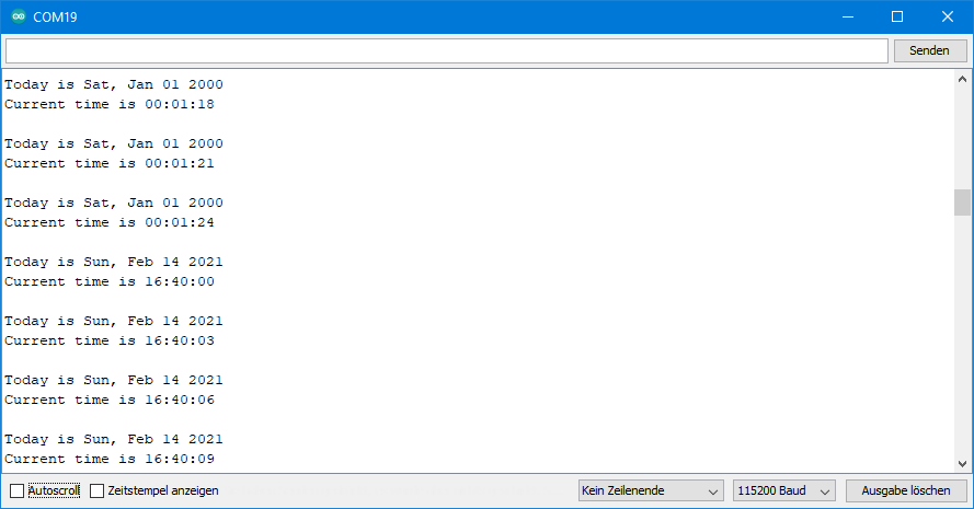
Ideally, the software clock is set to the DCF77 time after one to two minutes, as here. In case of poor reception, it may take longer.
A version of the sketch with a leaner ISR can be found in Appendix 1.
If you don’t want interrupts….
If you’re bothered by working with the interrupts, I have a version here without interrupts. Setting the clock is time-controlled. Since I had no desire to wait a long time, the clock is set every two minutes. Of course, this makes virtually no sense. However, you can easily change this to every few hours, for example.
The disadvantage of this method is that you can’t do anything else during the setting procedure.
The sketch is still quite communicative. You can cut it significantly if you want to use it or build on it.
#include "RTClib.h"
#include <util/parity.h> //comment out if you don't use an AVR MCU
int dataPin = 7;

RTC_Millis rtc;

void setup () {
  bool validTime = false;
  Serial.begin(115200);

#ifndef ESP8266
  while (!Serial); // wait for serial port to connect. Needed for native USB
#endif

  pinMode(dataPin, INPUT);

  DateTime currentTime = DateTime(2000, 1, 1, 0, 0, 0); // Initial Date

  while(!validTime){

    if(getDcf77Time(currentTime)){
      Serial.println("Date and Time updated!");
      validTime = true;
    }
    else{
      Serial.println("Sorry, something went wrong!");
    }
  }
  rtc.adjust(currentTime);
}

bool getDcf77Time(DateTime &dcf77Time){
  unsigned long long dcf77Sequence = 0;
  bool successfulUpdate = true;

  if(receiveSequence(dcf77Sequence)){
    Serial.println("Sequence OK - received 59 bits");
    printSequence(dcf77Sequence);
  }
  else{
    Serial.println("Sequence NOT OK - wrong nuber of bits");
    successfulUpdate = false;
  }

  if(evaluateSequence(dcf77Sequence, dcf77Time)){
    Serial.println("Valid Sequence!");
  }
  else{
    Serial.println("Invalid Sequence!");
    successfulUpdate = false;
  }

  return successfulUpdate;
}

bool evaluateSequence(unsigned long long &buf, DateTime &dcf77Time){
  bool parityOK = true;
  uint8_t dcf77Year = (buf>>50) & 0xFF;    // year = bit 50-57
  uint8_t dcf77Month = (buf>>45) & 0x1F;       // month = bit 45-49
  uint8_t dcf77DayOfWeek = (buf>>42) & 0x07;   // day of the week = bit 42-44
  uint8_t dcf77DayOfMonth = (buf>>36) & 0x3F;  // day of the month = bit 36-41
  uint8_t dcf77Hour = (buf>>29) & 0x3F;       // hour = bit 29-34
  uint8_t dcf77Minute = (buf>>21) & 0x7F;     // minute = 21-27
  bool parityBitMinute = (buf>>28) & 1;
  bool parityBitHour = (buf>>35) & 1;
  bool parityBitDate = (buf>>58) & 1;

  if((parity_even_bit(dcf77Minute)) != parityBitMinute){
    parityOK = false;
    Serial.println("Minutes not OK");
  }

  if((parity_even_bit(dcf77Hour)) != parityBitHour) {
    parityOK = false;
    Serial.println("Hours not OK");
  }

  if(((parity_even_bit(dcf77DayOfMonth) + parity_even_bit(dcf77DayOfWeek)
  + parity_even_bit(dcf77Month) + parity_even_bit(dcf77Year))%2) != parityBitDate)
  {
    parityOK = false;
    Serial.println("Date not OK");
  }

  if(parityOK==false) {
    return parityOK;
  }

  dcf77Time = DateTime(rawByteToInt(dcf77Year) + 2000, rawByteToInt(dcf77Month),
              rawByteToInt(dcf77DayOfMonth), rawByteToInt(dcf77Hour), rawByteToInt(dcf77Minute), 0);

  return parityOK;
}

unsigned int rawByteToInt(uint8_t raw){
  return ((raw>>4)*10 + (raw &0x0F));
}

bool receiveSequence(unsigned long long &buf){
  unsigned int counter = 0;
  unsigned int lowCounter = 0;
  unsigned int highCounter = 0;

  Serial.println("Waiting for sequence start...");
  waitForSequenceStart();
  Serial.println("HIGH / LOW");

  while(lowCounter < 150){
    lowCounter = 0;
    highCounter = 0;

    while(digitalRead(dataPin)) {
      delay(10);
      highCounter++;
    }
    if(highCounter >= 15){
      buf |= ((unsigned long long)1<<counter);
    }

    while(!digitalRead(dataPin)) {
      delay(10);
      lowCounter++;
    }

    Serial.print(counter);
    Serial.print(".  ");
    Serial.print(highCounter);
    Serial.print("  /  ");
    Serial.println(lowCounter);

    counter++;
  }
  if(counter==59){
    return true;
  }
  else{
    return false;
  }
}

void waitForSequenceStart() {
  unsigned int lowCounter2 = 0;

  while(lowCounter2<150){
    lowCounter2 = 0;
    while(digitalRead(dataPin)) {}
    while(!digitalRead(dataPin)) {
      delay(10);
      lowCounter2++;
    }
  }
}

void printSequence(unsigned long long &buf){
  unsigned long highBuf = (buf>>32) & 0x7FFFFFF;
  unsigned long lowBuf = (buf & 0xFFFFFFFF);
  Serial.print("Sequence, upper 4 bytes: ");
  Serial.println(highBuf, BIN);
  Serial.print("Sequence, lower 4 bytes: ");
  Serial.println(lowBuf, BIN);
}

void loop () {
  DateTime now = rtc.now();
  TimeSpan updatePeriod = TimeSpan(0,0,2,0);
  static DateTime nextUpdate = now + updatePeriod;

  char buf1[] = "Today is DDD, MMM DD YYYY";
  Serial.println(now.toString(buf1));
  char buf2[] = "Current time is hh:mm:ss";
  Serial.println(now.toString(buf2));
  Serial.println();

  if(nextUpdate < now){
    if(getDcf77Time(now)){
      rtc.adjust(now);
      nextUpdate = now + updatePeriod;
    }
  }

  delay(3000);
}

//uncomment the following lines if you don't use an AVR MCU
//bool parity_even_bit(uint8_t val){
//  val ^= val >> 4;
//  val ^= val >> 2;
//  val ^= val >> 1;
//  val &= 0x01;
//  return val;
//}
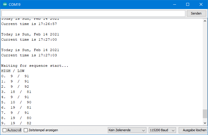
Output of dcf77_softRTC_without_interrupt.ino
Here’s what the sketch looks like in action:
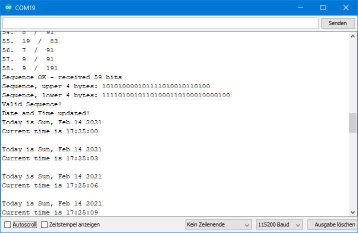
In the upper screenshot you can see that the clock is set at 5:25 p.m. As specified in the sketch, the next setting is two minutes later:
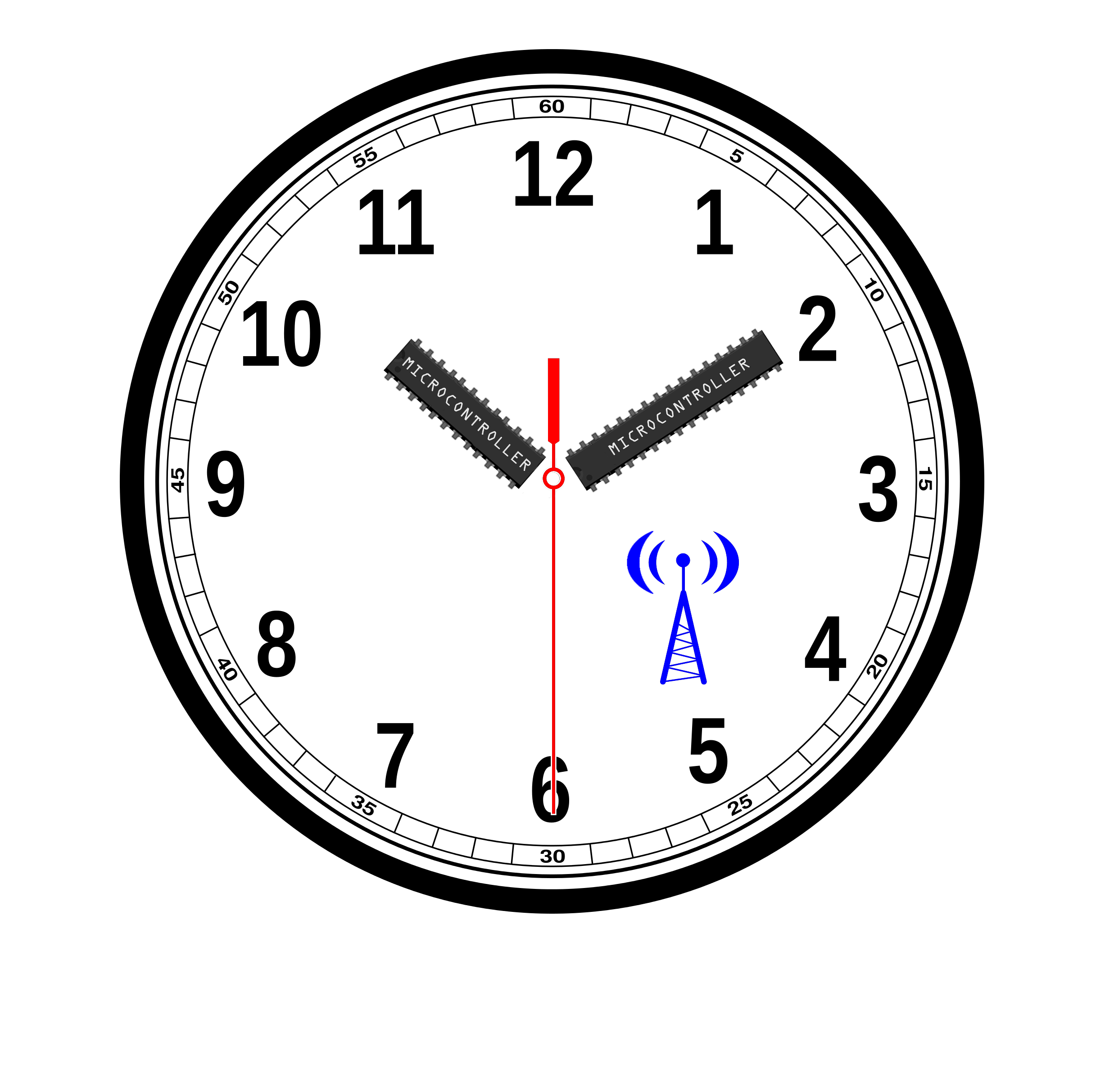
Acknowledgement
The basis of the post image, the watch, comes from OpenClipart-Vectors. I owe the radio symbol to Clker-Free-Vector-Images. Both are – as usual – from Pixabay.
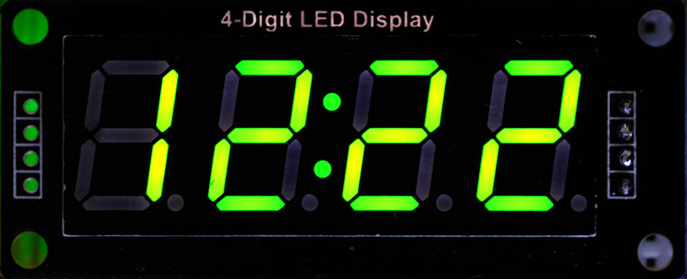
Appendix 1 – Time on a 4-digit display
And then I wrote a sketch that displays the time on a TM1637-based 4-digit display. I used the TM1637 library from Avishay, which you can also install via the Arduino library manager.
The watch can then look like this:
The sketch has become quite extensive. Theoretically, you could omit the detour via the soft RTC and translate the sequence directly into the time. However, this has the disadvantage that an incorrect sequence would lead to an incorrect or outdated time. In my implementation, only the soft RTC is not readjusted in the event of an incorrect sequence. But for one or a few minutes, you should be able to live with the less accurate soft RTC.
#include <util/parity.h> //comment out if you don't use an AVR MCU
#include "RTClib.h"
#include <TM1637Display.h>
#define CLK 9 // Display pin CLK
#define DIO 10 // Display pin DIO

int interruptPin=2;
volatile unsigned long lastInt = 0;
volatile unsigned long long currentBuf = 0;
volatile unsigned long long nextBuf = 0;
volatile bool newMinute = false;
volatile bool timeValid = false;
volatile byte bufCounter;

RTC_Millis rtc;
TM1637Display display(CLK, DIO);

void setup(){
  rtc.adjust(DateTime(2000, 1, 1, 0, 0, 0));
  display.setBrightness(0x0f);
  pinMode(interruptPin, INPUT);
  attachInterrupt(digitalPinToInterrupt(interruptPin), DCF77_ISR, CHANGE);
}

void loop(){
  static DateTime now = rtc.now();
  if(newMinute){
    if(timeValid){
      evaluateSequence();
    }
    else delay(2000); // if time not valid and soft rtc is slow
    now = rtc.now();
    int timeAsInt = now.minute() + now.hour() * 100;
    display.showNumberDecEx(timeAsInt, 0b11100000, true);
    //display.showNumberDec(timeAsInt, true); // without "__:__"
    newMinute = false;
  }
}

void DCF77_ISR(){
  unsigned int dur = 0;
  dur = millis() - lastInt;

  if(digitalRead(interruptPin)){
    if(dur>1500){
      if(bufCounter==59){
        timeValid = true;
        currentBuf = nextBuf;
      }
      else {
        timeValid = false;
      }
      nextBuf = 0;
      newMinute = true;
      bufCounter = 0;
    }
  }
  else{
    if(dur>150){
      nextBuf |= ((unsigned long long)1<<bufCounter);
    }
    bufCounter++;
  }
  lastInt = millis();
}

void evaluateSequence(){
  byte dcf77Year = (currentBuf>>50) & 0xFF;    // year = bit 50-57
  byte dcf77Month = (currentBuf>>45) & 0x1F;       // month = bit 45-49
  byte dcf77DayOfWeek = (currentBuf>>42) & 0x07;   // day of the week = bit 42-44
  byte dcf77DayOfMonth = (currentBuf>>36) & 0x3F;  // day of the month = bit 36-41
  byte dcf77Hour = (currentBuf>>29) & 0x3F;       // hour = bit 29-34
  byte dcf77Minute = (currentBuf>>21) & 0x7F;     // minute = 21-27
  bool parityBitMinute = (currentBuf>>28) & 1;
  bool parityBitHour = (currentBuf>>35) & 1;
  bool parityBitDate = (currentBuf>>58) & 1;

  if((parity_even_bit(dcf77Minute)) == parityBitMinute){
    if((parity_even_bit(dcf77Hour)) == parityBitHour){
      if(((parity_even_bit(dcf77DayOfMonth) + parity_even_bit(dcf77DayOfWeek)
           + parity_even_bit(dcf77Month) + parity_even_bit(dcf77Year))%2) == parityBitDate){
        rtc.adjust(DateTime(rawByteToInt(dcf77Year) + 2000, rawByteToInt(dcf77Month),
            rawByteToInt(dcf77DayOfMonth), rawByteToInt(dcf77Hour), rawByteToInt(dcf77Minute), 0));
      }
    }
  }
}

unsigned int rawByteToInt(byte raw){
  return ((raw>>4)*10 + (raw & 0x0F));
}

//uncomment the following lines if you don't use an AVR MCU
//bool parity_even_bit(byte val){
//  val ^= val >> 4;
//  val ^= val >> 2;
//  val ^= val >> 1;
//  val &= 0x01;
//  return val;
//}
Appendix 2 – Setting the DS3231 with the DCF77
You can simulate a DS3231 with a DCF77. The combination of these modules makes sense if you don’t have reliable reception with the DCF77. You can find the circuit and my sketch in this article.
Mr Ewald,
They say: an old dog should not learn new tricks. But at 75 years young i started a new hobby. CNC milling. And during 2 years i learned working with it. I am busy making digital clocks. Using ws2812 neopixel leds. A 60 led circle for the minutes and seconds and a 12 led circle for the hours. Using arduino mcu’s for the electronics. And because Europe has DST the clockreading is half of the year incorrect. So using a dcf77 module could be the answer. But i can not program an arduino. Elektronics are in my case not the goals, just a possibility making the clocks work. And i am too old for learning programming the arduino. So now my problem. I like your dcf77 softrtc sketch and i have it working.perfectly. But can you change the sketch for me so the dcf77 module is updating a ds3231 rtc module. I would be thankfull. If you answer me through my e-mail i could send you some pictures of the woodwork of the clocks in return. With the very best wishes, Hero Drent
Dear Hero Drent,
I hate to say no but I have to. I get a lot of requests by comments, by e-mail and via GitHub. Mostly no big deals, but things add up. 10 minutes here, 20 minutes there and then another evening is gone. With writing new articles, my job, family and some sports there is simply no time left. I hope you understand that.
Best wishes, Wolfgang
Sorry for the late reply. I have to understand you cannot help me in this case. But in my opinion it still is a pity. Best wishes Hero Drent
Hello Mr Drent, did you find somebody that helped you to get DCF77 time running? If not pls send me a personal message to get in contact…