
About this post
In this article I would like to introduce the real-time clock module DS3231. For this, I use the RTCLib library from Adafruit, as I think it is the best compromise of usability and completeness.
With the help of example sketches I will introduce you step by step to the functions of the DS3231 and the library. Since I found the original example sketches a bit confusing, I modified them slightly and added my own.
With the RTCLib, you can also control the alternative real-time clocks DS1307, PCF8523 and PCF8563. I will briefly deal with this at the end of this post. You can find a separate post about the DS1302, the DS1307, and the “Rtc by Makuna” library here.
As usual, I will first go a little further and introduce the features of the DS3231 module.
What is a real-time clock?
In other words, is there also an “unreal-time clock”? Well, even the Arduino boards measure the time. You can use the millis() function to query the time in milliseconds that has elapsed since the program was started. However, the Arduino does not know the time or the date. Real-time clocks, on the other hand, have registers that store the date and time. In addition, they are battery-powered and therefore do not “forget” this data. These features turn them into real-time clocks.
The DS3231 module

The DS3231 in a narrower sense is the large IC with the 16 pins, which can be easily recognized on the board. A data sheet about it can be found here. In this article, however, I always refer to the module, even if I speak of the DS3231 in short form.
Technical features of the DS3231
The most important features in my view are:
- Counts seconds, minutes, hours, days, days of the week, months, years.
- Including leap year function.
- Maximum deviation (at 0 to 40 °C): +/-2 ppm (equivalent to +/-63 seconds / year).
- Power supply: 2.3 – 5.5 volts.
- (Rechargeable) Battery: CR2032 /LIR2032, built-in charging function
- be careful when batteries (see note below!).
- Power consumption in VCC operation (own measurement):
- at 5 volts: 3.6 mA (with LED) / 0.64 mA (LED removed).
- at 3.3 volts: 1.8 mA (with LED) / 0.36 mA (LED removed).
- Battery power consumption: 0.84 – 3.0 µA (timekeeping mode).
- Two programmable alarms with interrupt function.
- Programmable output for square wave signals (I do not go into this in detail).
- Integrated temperature sensor, but with modest accuracy (+/-3 °C).
- Communication: I2C, address: 0x68, integrated pull-up resistors.
- Inputs/outputs:
- VCC / GND: Supply voltage
- SDA / SCL: I2C
- SQW: Output for square wave signals or low-active interrupt
- 32K: Output for square wave signal with 32 kHz (fixed)
Be careful using batteries
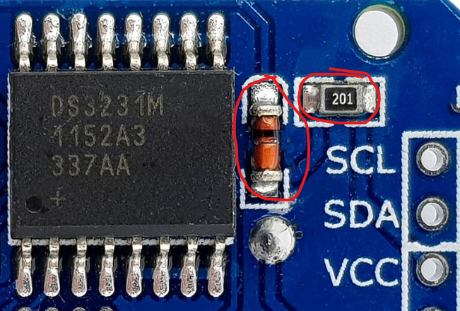
The DS3231 and other RTC modules have a charging circuit for LIR2032, i.e. rechargeable batteries. You can recognize this by the presence of a diode (see picture on the right). Many stores and deliver the module with a CR2032, i.e. a non-rechargeable button cell. This can be dangerous because the module still tries to charge the button cell. It can then inflate due to gas development, be destroyed and emit very unhealthy hydrofluoric acid in the process.
Unfortunately, the charging circuit is also only suitable for LIR2032 batteries to a very limited extent. Typically, a LIR is charged with 4.2 V. At 5 volts supply voltage I measured 4.75 volts at the contacts of the battery holder.
My recommendation: Remove the diode and / or the 200 Ohm resistor next to the diode when using a rechargeable or non-rechargeable button cell in parallel to an external power supply.

In case of doubt you can supply the DS3231 via VCC for testing and measure the voltage at the contacts of the battery holder.
Integrated EEPROM
You may have wondered what the small, eight-pin IC and the three address jumpers are all about. This IC is an EEPROM called AT24CS32. A data sheet can be found here. The AT24CS32 has a capacity of 32 kBit. So you can store a lot of data on it. Together with the DS3231, for example, you could regularly record readings from a sensor. Or you can save events, e.g. the times when a motion detector triggers.
Unlike the DS3231, you can modify the I2C address of the AT24CS32. If all jumpers are open, the address is 0x57. By closing jumpers you can set the addresses 0x50 to 0x56. If you want to check the addresses, you find an IC2 scanner here.
The RTCLib has not implemented any functions to use the EEPROM. I will therefore not go into any further detail.
Connection of the DS3231 to an Arduino UNO
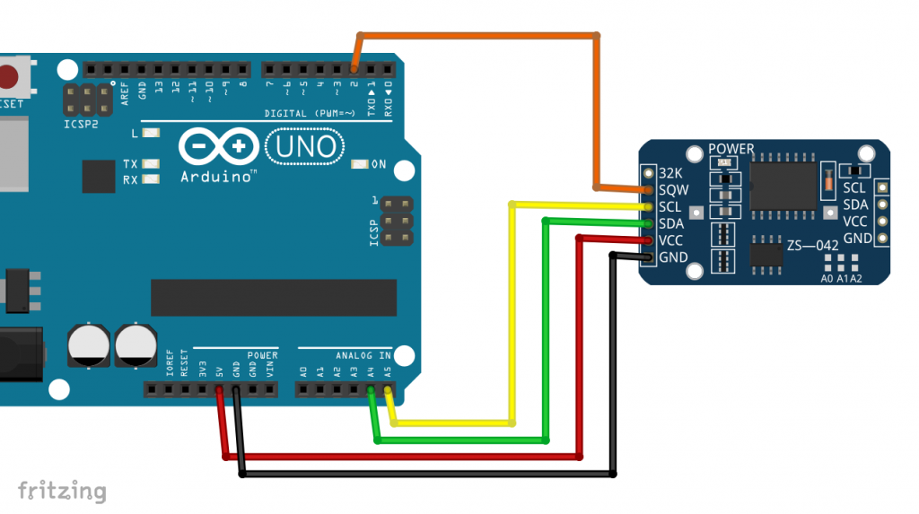
As you can see, the wiring is simple. Alternatively, you could connect VCC to 3.3 volts. But then charging the battery won’t work. Pull-ups for the I2C lines are not required. I use SQW as an interrupt output in some sketches.
Installing the RTCLib for the DS3231
You can install the RTCLib (Adafruit) via the Arduino IDE Library Manager:

Alternatively, download the library here from GitHub.
RTCLib requires another library called Adafruit BusIO. You can also find it via the library manager or here on GitHub.
Introduction to RTCLib
As announced, I’ll explain the features of the RTCLib to you using a series of example sketches.
Setting and querying the time
Of course, when you use the DS3231 for the first time, it doesn’t know the current time and date. This is like any other watch that is not a radio clock. There are two ways to set it:
rtc.adjust(DateTime(F(__DATE__), F(__TIME__)));conveniently uses the system time of your computer. However, this is the time when the sketch is compiled. Your clock will then be a few seconds pastrtc.adjust(DateTime(2014, 1, 21, 3, 0, 0));sets the date according to the scheme: year, month, day, hour, minute, second. Further below, I will show you how to set the time using this function via the serial monitor.
For the definition of specific times (date and time of day) there is a useful class in the RTCLib called DateTime.
DateTime now = rtc.now();creates the object “now” of the DateTime class and assigns the current time to it withrtc.now();.
Didactically, it may not be ideal to use the same name for the “now” object and the now(); function. I copied that from the original example sketches.
You access the years, months, days, hours, minutes and seconds of the DateTime object “now” with now.year(), now.month();, etc.
#include "RTClib.h"

RTC_DS3231 rtc;

char daysOfTheWeek[7][12] = {"Sunday", "Monday", "Tuesday", "Wednesday", "Thursday", "Friday", "Saturday"};

void setup () {
  Serial.begin(9600);

#ifndef ESP8266
  while (!Serial); // wait for serial port to connect. Needed for native USB
#endif

  if (! rtc.begin()) {
    Serial.println("Couldn't find RTC");
    Serial.flush();
    abort();
  }

    Serial.println("Setting the time...");
    // When time needs to be set on a new device, or after a power loss, the
    // following line sets the RTC to the date & time this sketch was compiled
     rtc.adjust(DateTime(F(__DATE__), F(__TIME__)));
    // This line sets the RTC with an explicit date & time, for example to set
    // January 21, 2014 at 3am you would call:
    // rtc.adjust(DateTime(2014, 1, 21, 3, 0, 0));
  }


void loop () {
    DateTime now = rtc.now();

    Serial.print(now.year(), DEC);
    Serial.print('/');
    Serial.print(now.month(), DEC);
    Serial.print('/');
    Serial.print(now.day(), DEC);
    Serial.print(" (");
    Serial.print(daysOfTheWeek[now.dayOfTheWeek()]);
    Serial.print(") ");
    Serial.print(now.hour(), DEC);
    Serial.print(':');
    Serial.print(now.minute(), DEC);
    Serial.print(':');
    Serial.print(now.second(), DEC);
    Serial.println();

    Serial.println();
    delay(3000);
}
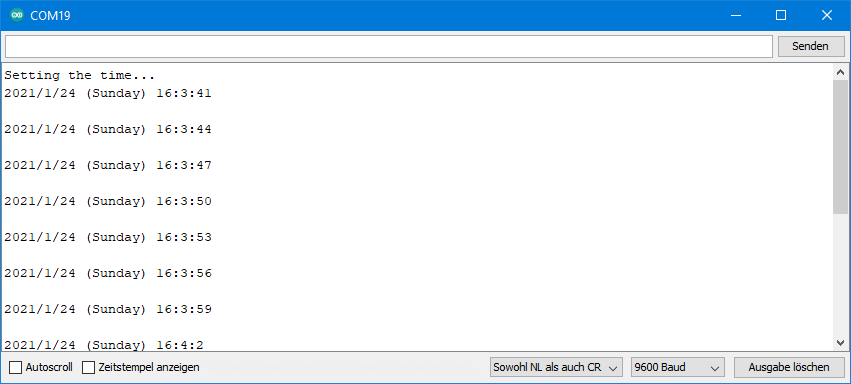
Output of SetTime.ino
More functions for reading time and date
Now you’ll get to know a few more basic functions. With rtc.lostPower(); you check whether the DS3231 was disconnected from the power. If this was the case, you can automatically re-set the time.
The RTCLib allows you to comfortably calculate with dates and times. TimeSpan(days, hours, minutes, seconds); or TimeSpan(seconds); define a time period that you can add to or deduct from a date.
Use now.unixtime(); to get the seconds that have elapsed between the time “now” and 1/1/1970 (UTC). This so-called Unix time is often used as a reference. You can query the current Unix time here on the net. More information about the Unix time can be found here.
The temperature measured by the integrated sensor in degrees Celsius can be obtained with rtc.getTemperature();.
// Date and time functions using a DS3231 RTC connected via I2C and Wire lib
#include "RTClib.h"

RTC_DS3231 rtc;

char daysOfTheWeek[7][12] = {"Sunday", "Monday", "Tuesday", "Wednesday", "Thursday", "Friday", "Saturday"};

void setup () {
  Serial.begin(9600);

#ifndef ESP8266
  while (!Serial); // wait for serial port to connect. Needed for native USB
#endif

  if (! rtc.begin()) {
    Serial.println("Couldn't find RTC");
    Serial.flush();
    abort();
  }

  if (rtc.lostPower()) {
    Serial.println("RTC lost power, let's set the time!");
    // When time needs to be set on a new device, or after a power loss, the
    // following line sets the RTC to the date & time this sketch was compiled
    // rtc.adjust(DateTime(F(__DATE__), F(__TIME__)));
    // This line sets the RTC with an explicit date & time, for example to set
    // January 21, 2014 at 3am you would call:
    // rtc.adjust(DateTime(2014, 1, 21, 3, 0, 0));
  }

  // When time needs to be re-set on a previously configured device, the
  // following line sets the RTC to the date & time this sketch was compiled
  // rtc.adjust(DateTime(F(__DATE__), F(__TIME__)));
  // This line sets the RTC with an explicit date & time, for example to set
  // January 21, 2014 at 3am you would call:
  // rtc.adjust(DateTime(2014, 1, 21, 3, 0, 0));
}

void loop () {
    DateTime now = rtc.now();

    Serial.print(now.year(), DEC);
    Serial.print('/');
    Serial.print(now.month(), DEC);
    Serial.print('/');
    Serial.print(now.day(), DEC);
    Serial.print(" (");
    Serial.print(daysOfTheWeek[now.dayOfTheWeek()]);
    Serial.print(") ");
    Serial.print(now.hour(), DEC);
    Serial.print(':');
    Serial.print(now.minute(), DEC);
    Serial.print(':');
    Serial.print(now.second(), DEC);
    Serial.println();

    Serial.print(" since midnight 1/1/1970 = ");
    Serial.print(now.unixtime());
    Serial.print("s = ");
    Serial.print(now.unixtime() / 86400L);
    Serial.println("d");

    // calculate a date which is 7 days, 12 hours, 30 minutes, 6 seconds into the future
    DateTime future (now + TimeSpan(7,12,30,6));

    Serial.print(" now + 7d + 12h + 30m + 6s: ");
    Serial.print(future.year(), DEC);
    Serial.print('/');
    Serial.print(future.month(), DEC);
    Serial.print('/');
    Serial.print(future.day(), DEC);
    Serial.print(' ');
    Serial.print(future.hour(), DEC);
    Serial.print(':');
    Serial.print(future.minute(), DEC);
    Serial.print(':');
    Serial.print(future.second(), DEC);
    Serial.println();

    Serial.print("Temperature: ");
    Serial.print(rtc.getTemperature());
    Serial.println(" C");

    Serial.println();
    delay(3000);
}
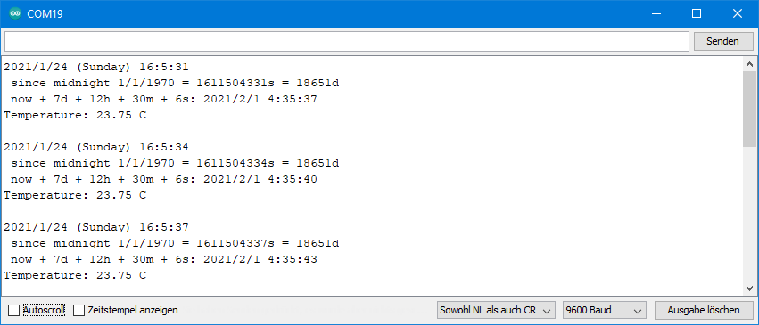
Output of ds3231.ino
Formatting date and time conveniently
Perhaps it also bothered you that the last two sketches output the time without preceding zeros. A time formatted like 1:2:3 looks ugly. 01:02:03 would be better. With the RTCLib, you can easily do this and other formatting of the time and date. I think the principle becomes clear through the following example sketch and I don’t have to write anything more about it.
#include <Wire.h>
#include <RTClib.h>
RTC_DS1307 rtc;
void setup () {
Serial.begin(9600);
#ifndef ESP8266
while (!Serial); // wait for serial port to connect. Needed for native USB
#endif
if (! rtc.begin()) {
Serial.println("Couldn't find RTC");
Serial.flush();
abort();
}
if (! rtc.isrunning()) {
Serial.println("RTC is NOT running, let's set the time!");
// When time needs to be set on a new device, or after a power loss, the
// following line sets the RTC to the date & time this sketch was compiled
// rtc.adjust(DateTime(F(__DATE__), F(__TIME__)));
// This line sets the RTC with an explicit date & time, for example to set
// January 21, 2014 at 3am you would call:
// rtc.adjust(DateTime(2014, 1, 21, 3, 0, 0));
}
// When time needs to be re-set on a previously configured device, the
// following line sets the RTC to the date & time this sketch was compiled
// rtc.adjust(DateTime(F(__DATE__), F(__TIME__)));
// This line sets the RTC with an explicit date & time, for example to set
// January 21, 2014 at 3am you would call:
// rtc.adjust(DateTime(2014, 1, 21, 3, 0, 0));
}
void loop() {
DateTime now = rtc.now();
//buffer can be defined using following combinations:
//hh - the hour with a leading zero (00 to 23)
//mm - the minute with a leading zero (00 to 59)
//ss - the whole second with a leading zero where applicable (00 to 59)
//YYYY - the year as four digit number
//YY - the year as two digit number (00-99)
//MM - the month as number with a leading zero (01-12)
//MMM - the abbreviated English month name ('Jan' to 'Dec')
//DD - the day as number with a leading zero (01 to 31)
//DDD - the abbreviated English day name ('Mon' to 'Sun')
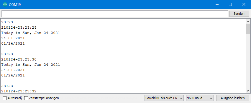
char buf1[] = "hh:mm";
Serial.println(now.toString(buf1));
char buf2[] = "YYMMDD-hh:mm:ss";
Serial.println(now.toString(buf2));
char buf3[] = "Today is DDD, MMM DD YYYY";
Serial.println(now.toString(buf3));
char buf4[] = "DD.MM.YYYY";
Serial.println(now.toString(buf4));
char buf5[] = "MM/DD/YYYY";
Serial.println(now.toString(buf5));
Serial.println();
delay(2000);
}
Output of toString.ino
Setting the time via the serial monitor
Based on the functions presented so far, you can conveniently set the time via the serial monitor:
#include "RTClib.h"

RTC_DS3231 rtc;

void setup () {
  Serial.begin(9600);

#ifndef ESP8266
  while (!Serial); // wait for serial port to connect. Needed for native USB
#endif

  if (! rtc.begin()) {
    Serial.println("Couldn't find RTC");
    Serial.flush();
    abort();
  }

  if (rtc.lostPower()) {
    rtc.adjust(DateTime(F(__DATE__), F(__TIME__)));
  }
  Serial.println("Enter the new time as hh:mm:ss");
}

void loop () {
  DateTime now = rtc.now();
  static int currentSecond = 61; // currentSecond to be different from first nextSecond
  int nextSecond = now.second();

  if(nextSecond != currentSecond){
    char buf1[] = "hh:mm:ss";
    Serial.println(now.toString(buf1));
    currentSecond = nextSecond;
  }

  if(Serial.available()){
    int newHour = Serial.parseInt();
    int newMinute = Serial.parseInt();
    int newSecond = Serial.parseInt();
    rtc.adjust(DateTime(now.year(),now.month(),now.day(),newHour, newMinute, newSecond));
    while(Serial.available()){
      Serial.read();
    }
  }
}
You enter the current hour, minute and second in the serial monitor. The year, month and day are taken from the currently set time.
Setting up an alarm with the DS3231
You can use the DS3231 as an alarm clock or a timer. There are two alarms available, but we will start by setting up one. You can use an interrupt to be informed about the alarm, or you actively ask regularly whether an alarm has been triggered.
But first you get to know the new rtc.disable32K(); function. This turns off the 32 kHz signal at pin “32K”.
With rtc.setAlarm1(); or rtc.setAlarm2(); you set up an alarm. The functions expect two arguments. The first argument is a time in the form of a DateTime object. In this sketch rtc.now(); + TimeSpan(); is used, i.e. the DS3231 acts as a timer. The second argument is best explained by examples:
DS3231_A1_Houris the common alarm setting. The alarm is triggered when the hour, minute and second match the specified alarm time. One alarm is triggered per day.DS3231_A1_Secondtriggers an alarm each time the current second matches the second which was set in the alarm time. The alarm is triggered once per minute.
There are even more options and confusingly the allowed parameters for Alarm1 and Alarm2 are different:

More functions for the DS3231 alarms
rtc.clearAlarm(1/2);clears the alarm. An alarm remains active until it is cleared.rtc.writeSqwPinMode(DS3231_OFF);deactivates the square wave signal at SQW so that the pin can be used as an interrupt pin.rtc.disableAlarm(1/2);deactivates the alarm function 1 or 2.rtc.alarmFired(1/2);checks whether Alarm1 or Alarm2 has been triggered (register check).
The following sketch triggers an alarm in 10 seconds.
/* Example implementation of an alarm using DS3231
 *
 * VCC and GND of RTC should be connected to some power source
 * SDA, SCL of RTC should be connected to SDA, SCL of arduino
 * SQW should be connected to CLOCK_INTERRUPT_PIN
 * CLOCK_INTERRUPT_PIN needs to work with interrupts
 */

#include <RTClib.h>
// #include <Wire.h>

RTC_DS3231 rtc;

// the pin that is connected to SQW
#define CLOCK_INTERRUPT_PIN 2

void setup() {
    Serial.begin(9600);
    // initializing the rtc
    if(!rtc.begin()) {
        Serial.println("Couldn't find RTC!");
        Serial.flush();
        abort();
    }

//    if(rtc.lostPower()) {
//        // this will adjust to the date and time at compilation
//        rtc.adjust(DateTime(F(__DATE__), F(__TIME__)));
//    }

    //we don't need the 32K Pin, so disable it
    rtc.disable32K();

    // Making it so, that the alarm will trigger an interrupt
    pinMode(CLOCK_INTERRUPT_PIN, INPUT_PULLUP);
    attachInterrupt(digitalPinToInterrupt(CLOCK_INTERRUPT_PIN), onAlarm, FALLING);

    // set alarm 1, 2 flag to false (so alarm 1, 2 didn't happen so far)
    // if not done, this easily leads to problems, as both register aren't reset on reboot/recompile
    rtc.clearAlarm(1);
    rtc.clearAlarm(2);

    // stop oscillating signals at SQW Pin
    // otherwise setAlarm1 will fail
    rtc.writeSqwPinMode(DS3231_OFF);

    // turn off alarm 2 (in case it isn't off already)
    // again, this isn't done at reboot, so a previously set alarm could easily go overlooked
    rtc.disableAlarm(2);

    // schedule an alarm 10 seconds in the future
    if(!rtc.setAlarm1(
            rtc.now() + TimeSpan(10),
            DS3231_A1_Second // this mode triggers the alarm when the seconds match. See Doxygen for other options
    )) {
        Serial.println("Error, alarm wasn't set!");
    }else {
        Serial.println("Alarm will happen in 10 seconds!");
    }
}

void loop() {
    // print current time
    char date[10] = "hh:mm:ss";
    rtc.now().toString(date);
    Serial.println(date);
    // resetting SQW and alarm 1 flag
    // using setAlarm1, the next alarm could now be configurated
    if(rtc.alarmFired(1)) {
        rtc.clearAlarm(1);
        Serial.println("Alarm cleared");
    }

    delay(2000);
}

void onAlarm() {
    Serial.println("Alarm occured!");
}
Output of ds3231_alarm_10s.ino

The alarm is retriggered every minute when the seconds match the alarm time.
Setting up two alarms
If you have understood how to set one alarm, then two alarms are not a problem either. I am not introducing any new functions here, and I think the sketch is self-explanatory along with the output on the serial monitor.
/* Example implementation of an alarm using DS3231
 *
 * VCC and GND of RTC should be connected to some power source
 * SDA, SCL of RTC should be connected to SDA, SCL of arduino
 * SQW should be connected to CLOCK_INTERRUPT_PIN
 * CLOCK_INTERRUPT_PIN needs to work with interrupts
 */

#include <RTClib.h>
// #include <Wire.h>

RTC_DS3231 rtc;

// the pin that is connected to SQW
#define CLOCK_INTERRUPT_PIN 2

void setup() {
    Serial.begin(9600);
    // initializing the rtc
    if(!rtc.begin()) {
        Serial.println("Couldn't find RTC!");
        Serial.flush();
        abort();
    }

//    if(rtc.lostPower()) {
//        // this will adjust to the date and time at compilation
//        rtc.adjust(DateTime(F(__DATE__), F(__TIME__)));
//    }

    //we don't need the 32K Pin, so disable it
    rtc.disable32K();

    // Making it so, that the alarm will trigger an interrupt
    pinMode(CLOCK_INTERRUPT_PIN, INPUT_PULLUP);
    attachInterrupt(digitalPinToInterrupt(CLOCK_INTERRUPT_PIN), onAlarm, FALLING);

    // set alarm 1, 2 flag to false (so alarm 1, 2 didn't happen so far)
    // if not done, this easily leads to problems, as both register aren't reset on reboot/recompile
    rtc.clearAlarm(1);
    rtc.clearAlarm(2);

    // stop oscillating signals at SQW Pin
    // otherwise setAlarm1 will fail
    rtc.writeSqwPinMode(DS3231_OFF);

    // turn off alarm 2 (in case it isn't off already)
    // again, this isn't done at reboot, so a previously set alarm could easily go overlooked
    rtc.disableAlarm(2);

    Serial.print("Start time: ");
    printTime();

    // schedule an alarm 30 seconds in the future
    rtc.setAlarm1(rtc.now() + TimeSpan(10), DS3231_A1_Second); // this mode triggers the alarm when the seconds match. See Doxygen for other options
    Serial.println("Alarm 1 will happen in 10 seconds!");

    // schedule an alarm 2 minutes in the future
    rtc.setAlarm2(rtc.now() + TimeSpan(0,0,2,0), DS3231_A2_Minute); // this mode triggers the alarm when the minutes match. See Doxygen for other options
    Serial.println("Alarm 2 will happen in 2 minutes (when full minutes match)!");
    Serial.println();

}

void loop() {
    // resetting SQW and alarm 1 flag
    // using setAlarm1, the next alarm could now be configurated
    if(rtc.alarmFired(1)) {
        printTime();
        rtc.clearAlarm(1);
        Serial.println("Alarm 1 cleared");
        Serial.println();
    }

    // resetting SQW and alarm 1 flag
    // using setAlarm1, the next alarm could now be configurated
    if(rtc.alarmFired(2)) {
        printTime();
        rtc.clearAlarm(2);
        Serial.println("Alarm 2 cleared");
        Serial.println();
    }
}

void printTime(){
     // print current time
    char date[10] = "hh:mm:ss";
    rtc.now().toString(date);
    Serial.println(date);
}

void onAlarm() {
    Serial.println("Alarm occured!");
}
Output of ds3231_2_alarms.ino
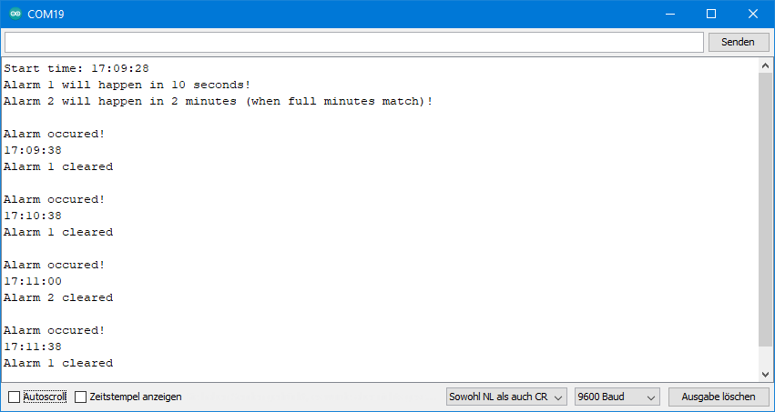
Here you can see the effect of the parameter D3231_A2_Minute.
Setting an alarm for a specific date
Again, no new functions are introduced in this sketch. It is only for deepening your knowledge.
#include <RTClib.h>
// #include <Wire.h>
RTC_DS3231 rtc;
// the pin that is connected to SQW
#define CLOCK_INTERRUPT_PIN 2
volatile bool alarm = false;
void setup() {
Serial.begin(9600);
if(!rtc.begin()) {
Serial.println("Couldn't find RTC!");
Serial.flush();
abort();
}
// if(rtc.lostPower()) {
// // this will adjust to the date and time at compilation
// rtc.adjust(DateTime(F(__DATE__), F(__TIME__)));
// }
//we don't need the 32K Pin, so disable it
rtc.disable32K();
// Making it so, that the alarm will trigger an interrupt
pinMode(CLOCK_INTERRUPT_PIN, INPUT_PULLUP);
attachInterrupt(digitalPinToInterrupt(CLOCK_INTERRUPT_PIN), onAlarm, FALLING);
// set alarm 1, 2 flag to false (so alarm 1, 2 didn't happen so far)
// if not done, this easily leads to problems, as both register aren't reset on reboot/recompile
rtc.clearAlarm(1);
rtc.clearAlarm(2);
// stop oscillating signals at SQW Pin
// otherwise setAlarm1 will fail
rtc.writeSqwPinMode(DS3231_OFF);
// turn off alarm 2 (in case it isn't off already)
// again, this isn't done at reboot, so a previously set alarm could easily go overlooked
rtc.disableAlarm(2);
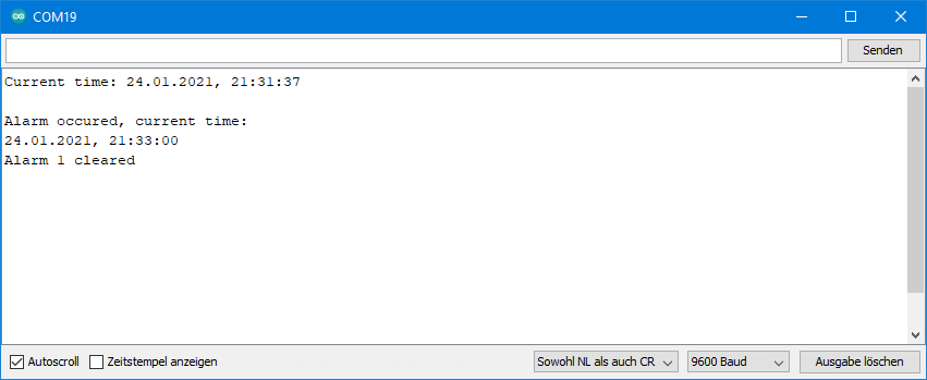
// schedule an Alarm for a certain date (day of month), hour, minute, and second
DateTime alarmTime (2021, 1, 24, 21, 33, 0);
rtc.setAlarm1(alarmTime, DS3231_A1_Date);
Serial.print("Current time: ");
printTime();
Serial.println();
}
void loop() {
if(alarm){
if(rtc.alarmFired(1)) {
Serial.println("Alarm occured, current time: ");
printTime();
rtc.clearAlarm(1);
Serial.println("Alarm 1 cleared");
}
}
}
void printTime(){
// print current time
DateTime now = rtc.now();
char date[] = "DD.MM.YYYY, ";
Serial.print(now.toString(date));
char time[] = "hh:mm:ss";
rtc.now().toString(time);
Serial.println(time);
}
void onAlarm() {
alarm = true;
}
Output of DS3231_alarm_fixed_time_and_date.ino
Setting date and time with a DCF77 module
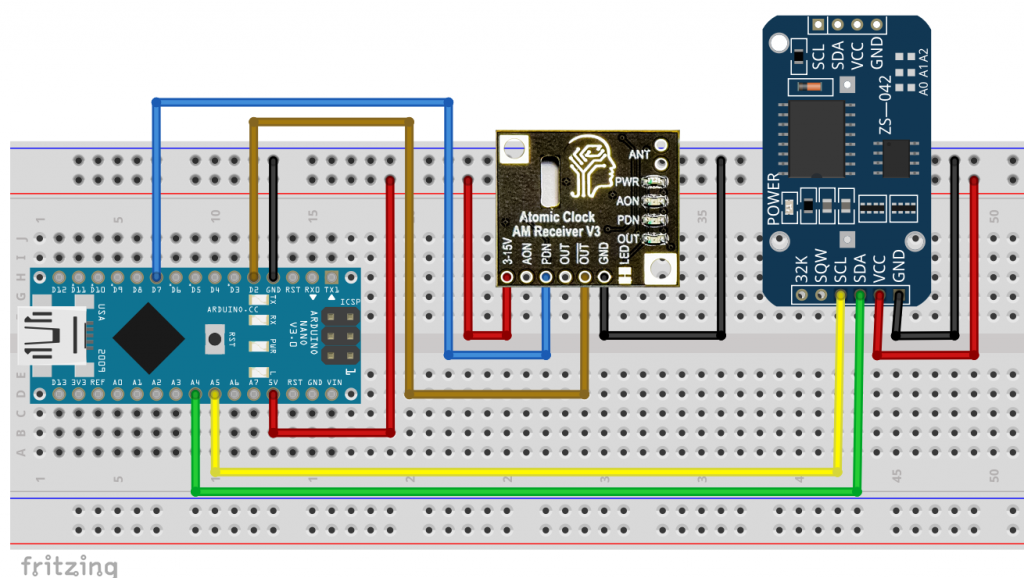
Perhaps you want to set the DS3231 automatically via a DCF77 module? This has the advantage that you wouldn’t have to worry about changing the summer and winter times. Here is the circuit with a DCF77 module from Canaduino:
In my example sketch, I set the DS3231 every five minutes. Of course, this makes no sense in practice, but you can use it to check that it actually works in a few minutes. The setting period can be easily adjusted.
#include <util/parity.h> //comment out if you don't use an AVR MCU
#include "RTClib.h"
#define DISPLAY_FQY 3000
#define ALARM_1 1
#define ALARM_2 2
#define TIME_ADJUST_PERIOD 300 // adjusment every 5 mins
int dcf77InterruptPin = 2;
int pcnPin = 7; // for Canaduino DCF77

volatile unsigned long lastDisplay = 0;
volatile unsigned long lastInt = 0;
volatile unsigned long long currentBuf = 0;
volatile unsigned long long nextBuf = 0;
volatile bool timeUpdateAvailable = false;
volatile byte bufCounter;

RTC_DS3231 rtc;

void setup(){
  Serial.begin(115200);
  pinMode(pcnPin, OUTPUT); // only for Canaduino DCF77
  if (! rtc.begin()) {
    Serial.println("Couldn't find RTC");
    Serial.flush();
    abort();
  }

  rtc.adjust(DateTime(2000, 1, 1, 0, 0, 0));
  rtc.disable32K();

  pinMode(dcf77InterruptPin, INPUT);
  attachInterrupt(digitalPinToInterrupt(dcf77InterruptPin), DCF77_ISR, CHANGE);
  rtc.clearAlarm(ALARM_1);
  rtc.clearAlarm(ALARM_2);
  rtc.disableAlarm(ALARM_2);
  rtc.writeSqwPinMode(DS3231_OFF);
}

void loop(){
  static DateTime now = rtc.now();

  if(timeUpdateAvailable){
    evaluateSequence();
    detachInterrupt(digitalPinToInterrupt(dcf77InterruptPin));
    Serial.println("Time Updated");
    // if you change TIME_ADJUST_PERIOD, you might also need to change DS3231_A1_Minute
    rtc.setAlarm1(rtc.now() + TimeSpan(TIME_ADJUST_PERIOD), DS3231_A1_Minute);
    rtc.clearAlarm(ALARM_1);
    timeUpdateAvailable = false;
  }

  if(rtc.alarmFired(ALARM_1)){
    rtc.clearAlarm(ALARM_1);
    attachInterrupt(digitalPinToInterrupt(dcf77InterruptPin), DCF77_ISR, CHANGE);
    Serial.println("Next time adjustment started...");
  }

  if (millis() - lastDisplay > DISPLAY_FQY){
    displayDateTime(&now);
  }

}

void displayDateTime(DateTime now){
  lastDisplay = millis();
  now = rtc.now();
  char buf1[] = "Today is DDD, MMM DD YYYY";
  Serial.println(now.toString(buf1));
  char buf2[] = "Current time is hh:mm:ss";
  Serial.println(now.toString(buf2));
  Serial.println();
}

void DCF77_ISR(){
  unsigned int dur = 0;
  dur = millis() - lastInt;

  if(digitalRead(dcf77InterruptPin)){
    if(dur>1500){
      if(bufCounter==59){
        timeUpdateAvailable = true;
        currentBuf = nextBuf;
      }
      bufCounter = 0;
      nextBuf = 0;
    }
  }
  else{
    if(dur>150){
      nextBuf |= ((unsigned long long)1<<bufCounter);
    }
    bufCounter++;
  }
  lastInt = millis();
}

void evaluateSequence(){
  byte dcf77Year = (currentBuf>>50) & 0xFF;    // year = bit 50-57
  byte dcf77Month = (currentBuf>>45) & 0x1F;       // month = bit 45-49
  byte dcf77DayOfWeek = (currentBuf>>42) & 0x07;   // day of the week = bit 42-44
  byte dcf77DayOfMonth = (currentBuf>>36) & 0x3F;  // day of the month = bit 36-41
  byte dcf77Hour = (currentBuf>>29) & 0x3F;       // hour = bit 29-34
  byte dcf77Minute = (currentBuf>>21) & 0x7F;     // minute = 21-27
  bool parityBitMinute = (currentBuf>>28) & 1;
  bool parityBitHour = (currentBuf>>35) & 1;
  bool parityBitDate = (currentBuf>>58) & 1;

  if((parity_even_bit(dcf77Minute)) == parityBitMinute){
    if((parity_even_bit(dcf77Hour)) == parityBitHour){
      if(((parity_even_bit(dcf77DayOfMonth) + parity_even_bit(dcf77DayOfWeek)
           + parity_even_bit(dcf77Month) + parity_even_bit(dcf77Year))%2) == parityBitDate){
        rtc.adjust(DateTime(rawByteToInt(dcf77Year) + 2000, rawByteToInt(dcf77Month),
            rawByteToInt(dcf77DayOfMonth), rawByteToInt(dcf77Hour), rawByteToInt(dcf77Minute), 0));
      }
    }
  }
}

unsigned int rawByteToInt(byte raw){
  return ((raw>>4)*10 + (raw & 0x0F));
}

//uncomment the following lines if you don't use an AVR MCU
//bool parity_even_bit(byte val){
//  val ^= val >> 4;
//  val ^= val >> 2;
//  val ^= val >> 1;
//  val &= 0x01;
//  return val;
//}
I won’t go into the details here. Everything related to the DS3231 should be understandable with the help of this article. For the DCF77 related code, take at this article.
PCF8523, PCF8563 and DS1307
With the RTCLib, you can also control the alternative real-time clocks PCF8523, PCF8563 and DS1307. I tried the PCF8523 and the DS1307. The RTCLib example sketches for these RTCs ran without any problems. The setting and reading of the time and date works as with the DS3231. The same applies to the pleasant computing functions using TimeSpan and the numerous formatting options for the output.
The PCF8523 (data sheet here) and the PCF8563 (data sheet here) are quite similar to the DS3231. At least I had the impression when flying over the registers in the data sheet. Unfortunately, the RTCLib does not seem to have implemented all available features. There is a countdown timer example sketch, but no classic alarm function.

The DS1307 is a bit simpler. It has no alarm function in itself. Like the DS3231, it has integrated an EEPROM and a battery charging function.

Software RTC
You can also use the time and date functions of the RTCLib without the RTC module. To do this, the current time is taken once from the computer’s system time during compilation and then updated with the millis() function. The example sketch softrtc.ino (which I don’t reprint here) shows you how to do it. The method has two drawbacks:
- The millis() method is much less accurate.
- Every time you reset or break the current power, the current time is lost.
For the advanced: The AVR based Arduino boards use the Timer0 and the associated Timer0 overflow interrupt for millis(). You can find the definitions in Arduino\hardware\arduino\avr\cores\arduino\wiring.c.
DS3231 Libraries: Alternatives to RTCLib
I also looked at a number of other libraries for the DS3132 on GitHub. If you find the RTCLib too big and complex, you could consider trying the DS3231_Simple library. The name says it: it’s simple. It has all the basic functions for reading and setting the time, including alarm programming. What it lacks (as of February 2020) are the alarm interrupts at the SQW pin. So, you have to check regularly if an alarm has been triggered. A clear advantage, however, is that the DS3231 also has functions for using the EEPROM.
The DS3132RTC library is very accurate and very complete. But it may be a bit hard to digest for the not-so-experienced Arduino fan. Look at the example sketches, then you know what I mean.
Acknowledgement
I would like to thank Adafruit for publishing their nice library.
The basis of my post picture, into which I inserted the DS3231, comes from andreas N (domeckopol) on Pixabay.
Setting the time from Serial monitor is very interesting. It’s a pity you didn’t go further.
I would like to see an example of setting the date and time from a web page if the ESP is in AP mode.
This might give you the right direction:
https://wolles-elektronikkiste.de/en/ds1302-and-ds1307-rtc-real-time-clock#set_time_google
It’s for the DS1302 / DS1307. So you need to adjust it.
Why does my ds1307 return exactly the same values every loop?
Which example sketch did you apply? For the DS1307 you should take the sketch ds1307.ino as a basis. An important difference to the DS3231 is that you need to start it with the isRunning() function. If this does not work, I recommend opening an issue on GitHub for the author of the library.
Alternatively have a look into my article about the DS1302 an DS1307:
https://wolles-elektronikkiste.de/en/ds1302-and-ds1307-rtc-real-time-clock
I used a different library there.
I already tried the sketch in ds1307_basic.ino but it returns the values; the time on which the code was compiled. Is there a chance that the problem is in my ds1307?
Update: I purchased ds1302 and it works fine. Unfortunately, ds1307 isn’t available at the store so i’ll have to wait for several days to confirm that the problem is in my ds1307. Thanks Wolfgang, your blog is teaching me far more than my university course 😀
ON DS3231 one can only set the time when there has been a rtc lost power.
how can one adjust the time of the DS3231 when power has not been lost?
One solution could be to interrupt the power and batery with a relay to force power lost and then first arm the Vc power and after taht the battery power.
But is there a more elegant method ?
Thanks a lot
With rtc.adjust(DateTime(F(__DATE__), F(__TIME__))); you should be able to set the time even if the power has not been lost. But this is just the time when the sketch is compiled.
Alternatively you cou set the time like did in the sketch setTime.ino.
if (rtc.lostPower()) {
rtc.adjust(DateTime(F(__DATE__), F(__TIME__)));
}
Serial.println(“Enter the new time as hh:mm:ss”);
}
But this works only if rtc lost power. I tried this before. Is there not a register for ower lost that can be set ? and how?
thanks
Just remove the if – construction:
if (rtc.lostPower()) {….}
and only leave what’s in the if construction:
rtc.adjust(DateTime(F(__DATE__), F(__TIME__)));
Thanks for the warning of hidden charging circuits on some RTC boards!
This is something that is easy to miss.
FWIW, at least the Adafruit D3231 RTC PCB does NOT include such a circuit: https://learn.adafruit.com/adafruit-ds3231-precision-rtc-breakout/downloads
The same goes for the Adafruit PCF8523 PCB.
How does the power consumption (in timekeeping mode) of the PCF8523 compares to the DS3231’s?
Looking at the datasheets the PCF8523 might require less current, but perhaps I’m interpreting them wrongly.
The power consumption depends on which functions are active. But I would also say that that the minimum power consumption of the PCF8523 is lower (in the nA range) compared to the DS3231 (in the µA range).
Indeed. FWIW, In the meantime I got my hands on some Adafruit PCF8523 and DS3231 PCBs and did some measurements. (after disabling the power-on LEDs)
I measured a PCF8523 power consumption of 200 nA (on VCC) after disabling clockout and battery-switchover (but alarm interrupt enabled). That increased to 1.45 µA when enabling battery-switchover.
With the DS3231 there is a big difference when powering it from VCC or VBAT. On VCC (clockout and SQW disabled, alarm enabled) I measured 84 µA, where VCC on is required for I2C communication. After shutting down VCC the module just consumes 820 nA via VBAT, though.
That means if you don’t need the battery backup (because – say – you only want to use the RTC for waking up the MCU from deep sleep via an alarm interrupt), then the PCF8523 consumes less power than the DS331. With battery backup required, the DS3231 wins, when VCC can be powered down for significant time spans, e.g. when powering it from an MCU GPIO output pin.