
Why do you need an I2C scanner?
In some posts I had dealt with components that are addressed by means of I2C (more precisely: I2C), as for example in my last article about the MCP23017. This post is about an I2C scanner sketch that you can use to find out I2C addresses.
In order to address several components via a single I2C bus, each of the components must have its own I2C address. The address space is limited to addresses from 1 to 127. Strictly speaking, even on 8 to 127, as addresses 0 to 7 are reserved. Since this is not very much, issues with duplicate addresses are not unlikely without further action. Therefore, most I2C components have two or three input pins, which you can set to LOW or HIGH to set multiple addresses. For modules, you can sometimes choose the address via jumpers.
Ideally, you will find a data sheet describing the addressing. Sometimes this is not the case and then you need an I2C scanner. O maybe a circuit just doesn’t work and you want to check if the I2C part you’re using is responding at all. Even then, an I2C scanner makes sense. In addition, you may want to check which transfer speed your I2C component is suitable for.
I2C – data transfer rate
The I2C bus consists of two lines, most commonly referred to as SDA and SCL. SDA transmits the data, SCL sets the clock and thus determines the data rate. There are 5 clock speeds:
- Standard Mode, clock: 100 kHz
- Fast Mode: 400 kHz
- Fast Mode Plus: 1 MHz
- High Speed Mode: 3.4 MHz
- Ultra Fast Mode: 5 MHz (unidirectional only)
Since one bit is transmitted at each bar, the clock rate corresponds to the data rate in bits/s.
Which clock can be set depends on both the I2C device and the microcontroller used. The Arduino Uno can only use the Fast Mode.
More information about I2C can be found here on Wikipedia. The Wire library is described on the Arduino web pages here.
The I2C scanner sketch
The sketch is very simple. Wire.setClock() sets the clock speed. Wire.beginTransmission(adresse) starts communication with the I2C device. Wire.endTransmission() returns “0” if it has worked. Thus, the sketch works slavishly through the address space for each transmission rate.
#include<Wire.h>

void setup(){
  Wire.begin();
  Serial.begin(9600);
  Serial.println("I2C scanner is ready.");
  Serial.println();
}

void loop() {
  scanI2C(100000);
  scanI2C(400000);
//  scanI2C(1000000); // uncomment if the microcontroller supports this speed
//  scanI2C(3400000); // uncomment if the microcontroller supports this speed
//  scanI2C(5000000); // uncomment if the microcontroller supports this speed

  Serial.println("****************************");
  Serial.println();
  delay(3000);
}

void scanI2C(long frequency){
  String normal = "standard mode (100 kHz):";
  String fast = "fast mode (400 kHz):";
  String fastPlus = "fast mode plus (1 MHz):";
  String highSpeed = "high speed mode (3.4 MHz):";
  String ultraSpeed = "ultra fast mode (5.0 MHz):";
  String defaultStr = " !!!!! This speed is not supported !!!!!";
  bool error = true;
  bool addressFound = false;

  Serial.print("Scanning in ");
  switch(frequency){
    case 100000:
      Serial.println(normal);
      break;
    case 400000:
      Serial.println(fast);
      break;
    case 1000000:
      Serial.println(fastPlus);
      break;
    case 3400000:
      Serial.println(highSpeed);
      break;
    case 5000000:
      Serial.println(ultraSpeed);
      break;
    default:
      Serial.println(defaultStr);
      break;
  }

  Wire.setClock(frequency);
  for(int i=1; i<128; i++){
    Wire.beginTransmission(i);
    error = Wire.endTransmission();
    if(error == 0){
      addressFound = true;
      Serial.print("0x");
      Serial.println(i,HEX);
    }
  }
  if(!addressFound){
    Serial.println("No I2C device found");
  }
  Serial.println();
}
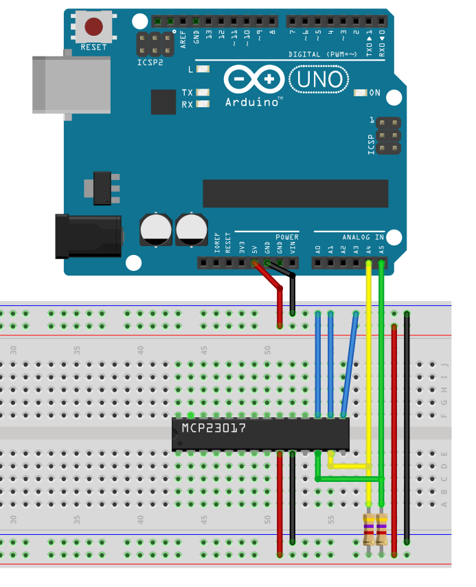
Example circuit: MCP23017
Here is an example circuit with the MCP23017. If the sketch doesn’t recognize an address, it could be due to missing pull-up resistors (4.7 kOhm).

Hello. can your scanner show the AM2320 address
Hi, as long as a device has an I2C interface and it is correctly connected, the scanner should be able to read the address. I could not test it with an AM2320, since do only have AM2302 devices which do not have an I2C interface. Why do you ask? Does it not work? If it does not work, have you used pull-up resistors?
FWIW, I wrote a simple ATmega328p I2C address scanner that doesn’t depend on the `Wire.h` library:
https://github.com/gsauthof/i2c-scanner/blob/master/atmega328p/src/main.c
Perhaps it’s also instructive for understanding how the Wire abstraction works under the hood.
Cool – thanks!