About this Post
Update 8 July 2022: In this post, I describe the “attiny” Board Manager package. However, I now recommend the superior “TinyCore” package from MCUdude. You can find the article here.
There are often projects for which you don’t really need the larger ATmega chips, such as the 328(P) or 168. These microcontrollers can be found e.g. on the Arduino Nano or the Arduino Pro Mini. If you aren’t already doing so, you should check whether, in some cases, you might be able to make do with the space- and energy-saving smaller versions – the ATtiny85, 84, 45, 44, 25 or 24 (in short: ATtiny85 & Co).
In this post I want to show you how to upload your sketches to ATtiny85 & Co with:
- the Arduino as a programmer and the Arduino IDE
- the USBtinyISP software and the Arduino IDE
- dem AVR Dragon oder Atmel-ICE und Atmel Studio
I will only touch briefly on the latter method, as a step-by-step guide would go beyond the scope of this article. I will cover this again at a later date as a separate topic.
Similarly, I won’t be discussing the features of the ATtinys and how they differ from their big brother, the ATmega, here, but in a separate post. This post focuses primarily on uploading.
If you want to make things even easier, you could also opt for the Digispark. This is an ATtiny85-based module that is programmed via USB. I’ve described it here.
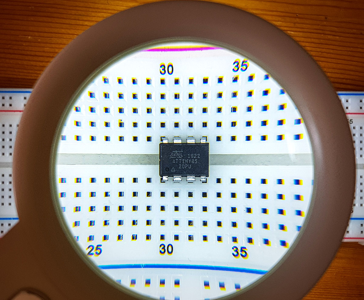
Pinout of ATtiny85 & Co

The pinout diagrams for the ATtiny85, 45 and 25 are identical. In addition to VCC and GND, there are six I/O pins which, as is customary with the ATmegas, have multiple functions. Pins 1, 5, 6 and 7 (also known as PB5, PB0, PB1 and PB2) are required for uploading sketches, representing RESET, MOSI, MISO and SCK respectively.
You can find a data sheet for this sub-family here, for example.

The pin-out diagrams for the ATtiny84, 44 and 24 are also identical. Unlike the ATtinyx5 series, these have 12 I/O pins. In the following, I will focus primarily on the ATtinyx5 series. It should be easy to adapt the circuits and explanations to the 4 series.
You can find a data sheet for this subfamily here.
Uploading with the Arduino IDE
Preparing the Arduino IDE for ATtiny85 & Co
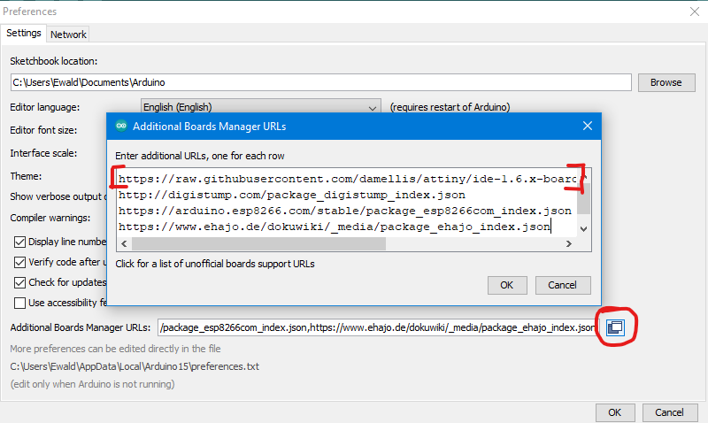
First, you need to teach the Arduino IDE how to work with ATtinys. To do this, the first step is to enter the relevant board manager URL in:
File -> Preferences -> Additional board manager URLs.
Click on the highlighted icon and, in the window that opens, add the line:
https://raw.githubusercontent.com/damellis/attiny/ide-1.6.x-boards-manager/package_damellis_attiny_index.json
. Then close the window by clicking “OK”.
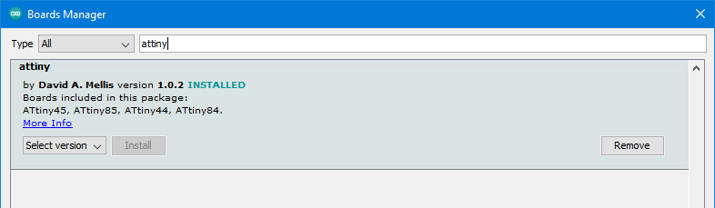
Next, go to:
Tools -> Board: …. -> Boards Manager
and search for “attiny”. Select the package by David A. Mellis and install it. Then restart the Arduino IDE, and that’s it.

Arduino as programmer for ATtiny85 & Co
Wiring
First of all, we’ll use an Arduino UNO as the programmer. A Nano, Mega, Pro Mini, etc. will work just as well, of course. My example application is a simple blinking sketch. You’ll find the circuit diagram for this below. The blinking LED is connected to PB4 (Pin 3). There is a 10 µF capacitor between the Arduino RESET pin and GND. This is recommended in many places, but it has always worked for me without this step. Otherwise, connect the components as follows:


Example sketch
I don’t think I need to add anything else about the schematic, except perhaps that the pin assignment refers to PBx and not to the pin number.
int ledPin = 4;

void setup() {
  pinMode(ledPin, OUTPUT);
}

void loop() {
  digitalWrite(ledPin, HIGH);
  delay(200);
  digitalWrite(ledPin, LOW);
  delay(200);
}
Upload
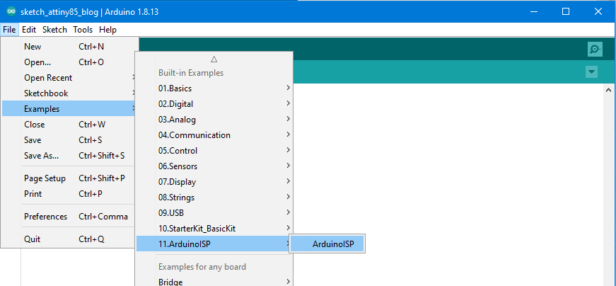
Now you need to make sure that the sketch is uploaded to the ATtiny and not the Arduino. To do this, first upload the ArduinoISP sketch from the examples to the Arduino. For this step, you should still select the Arduino UNO as the board. If you have a capacitor connected to the Arduino reset pin, remove it for this step!
Then select your ATtiny, the clock speed and, of course, the correct port:
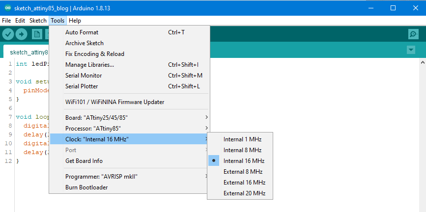
Finally, you need to choose the right programmer:
Tools -> Programmer -> “Arduino as ISP”
(not: ArduinoISP!). Then you’re all set and can finally upload the sketch.
Note: If you change the clock speed, and as a precaution before the first upload, you must burn the bootloader again. Try it out: upload the sample sketch with the selection of 16 MHz and then up another time with 1 MHz – if the bootloader is still the same, the flashing frequency at 16 MHz is sixteen times slower.
Little helpers
If you work with ATtinys a lot, I recommend investing in a breadboard adapter (on the left in the next picture), as it makes the setup much clearer. The adapter is particularly useful with the USBtinyISP programmer, which we’ll come to shortly. However, you can also use the adapter with an UNO if you build yourself a small shield. The breadboard adapter is available to buy here, for example, or with a 2 x 3 pin header here.


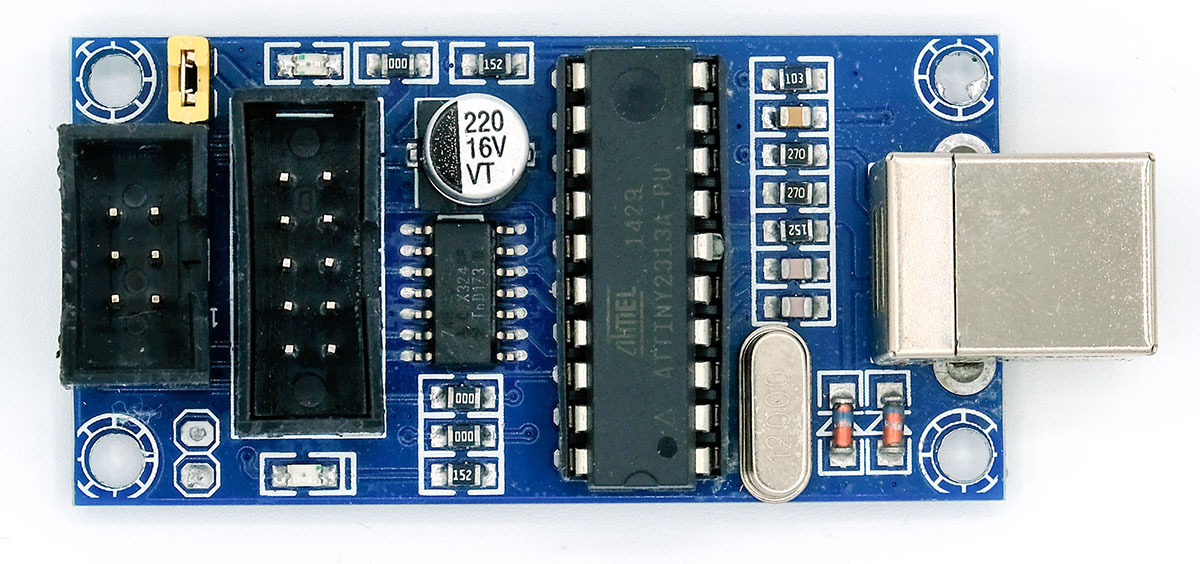
Uploading with USBtinyISP
The great thing about the Arduino as a programmer is that you’ve probably got one anyway. However, it’s more convenient to use a USBtinyISP programmer, as you don’t have to go via the ArduinoISP sketch. What’s more, you can plug a breadboard adapter straight onto it. The programmer is available for under < €10, for example from Amazon.
Preparation
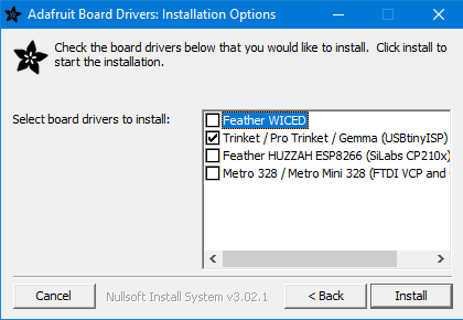
Even when using the programmer, you must, of course, have completed the steps under “Preparing the Arduino IDE” above. You will then also need a driver for the USBtinyISP. You can download the driver installer here. Run it, tick the box next to “Trinket / Pro Trinket / Gemma (USBtinyISP)” and click “Install”.
Wiring
The circuit is essentially the same as above, except that the programmer is used instead of the Arduino:

Upload
In der Arduino IDE wählt ihr als Programmer “USBtinyISP”. You’ll probably notice that ‘Port’ isn’t available as an option, even though you’ve connected the programmer. Don’t worry, that’s how it’s meant to be. Then select the ATtiny type and the clock speed, and you can upload the sketch. In older versions of the Arduino IDE, you’ll need to select ‘Upload via Programmer’ from the ‘Sketch’ menu or, alternatively, click the upload arrow while holding down the Shift key. In my version of the Arduino IDE (1.8.9), it works without these steps.
If it does not work
A notorious error message is “Could not find USBtiny device (0x1781/0xc9f)”:
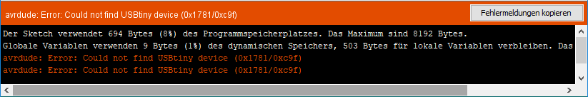
If you see this message even though the USBtinyISP is connected, it is most likely a driver issue. I’ve had this happen to me before. If you’re using Windows, go to Device Manager and look for the USBtinyISP. Check the driver details in the properties. This should look something like this (sorry, German Windows):
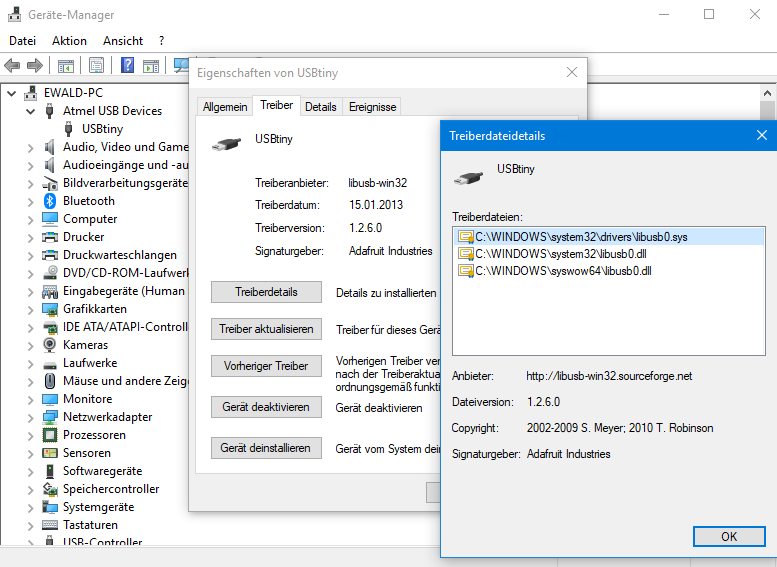
In my case, Windows had picked a different driver that I had on my computer. The solution: Click on “Update driver” –> “Browse my computer” –> “Pick from available…”. If several drivers are listed there, simply try them one by one.
Uploading with Atmel Studio
For the sake of completeness, I would like to include this option. However, the subject is so extensive that it would go beyond the scope of this post. I will therefore only touch on it briefly here and provide a step-by-step guide in a separate post.
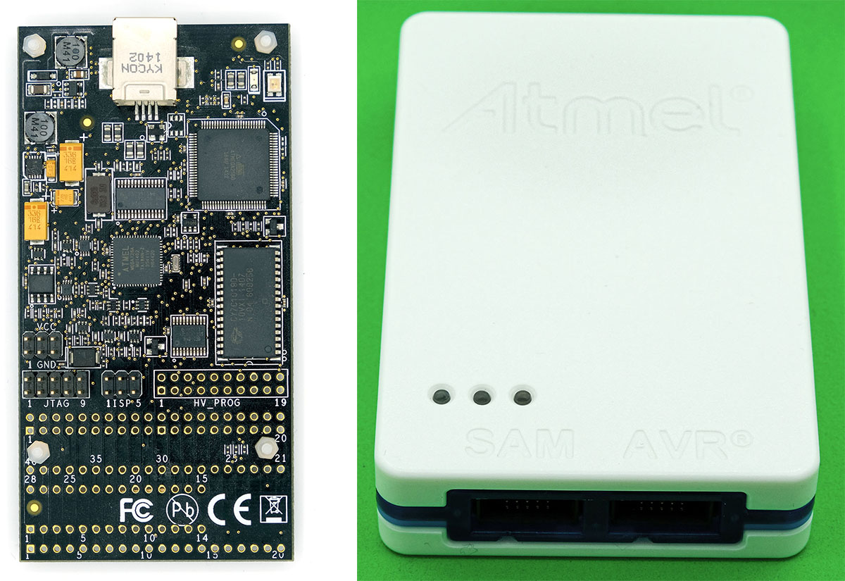
Atmel Studio (currently version 7) is a free IDE that you can download here. It includes everything you need in terms of software to programme Atmel microcontrollers.
Various programmers are available as suitable hardware, e.g. the AVR Dragon or Atmel-ICE:
The programmes written in Atmel Studio are usually written in C and are much closer to the hardware than the usual Arduino sketches. The Blink sketch looks like this:
#include <avr/io.h>
#include <util/delay.h>


int main(void)
{
    DDRB |= (1<<PB4);

  while (1)
  {
    PORTB = (1<<PB4);
    _delay_ms(500);
    PORTB &= ~(1<<PB4);
    _delay_ms(500);
    }
}
That might look a bit daunting, but it certainly has its advantages, for example in terms of speed. It also gives you a clearer picture of what’s actually happening at the level of ports and registers.
Other benefits of working with Atmel Studio and the programmers mentioned include:
- Access to the fuse bits
- Debugging: step-by-step program execution and variable tracking
- better structuring of large projects
The downside is that it takes some getting used to, and the programmers are expensive. Still keen to find out more? Then keep an eye out for our special feature on the subject.
Hi Wolfgang,
I just found your site & really enjoyed your articles on ATtiny85/ etc., and Digispark.
By the way, I think you probably speak English better than most Americans (no kidding).
Your writing is certainly clearer and more accurate.
Since you also have several I2C articles, (I have only read the I2C Scanner, TCA9548A – I2C Multiplexer, and ADS1115 – A/D converter with amplifier articles on that so far), I was wondering, do you plan to look at I2C OLED Displays and the ATtiny85 / Digispark?
Hope so…
Thanks again,
Joe
Hi Joe, thanks for your kind feedback which is very motivating. I haven’t planned an article about that topic yet, but I am always happy about suggestions. I will not promise anything, but at least I add it to my list of ideas! Best wishes, Wolfgang