In my last post, I described how to upload sketches to an ATtiny85 (or 84, 45, 44, 25, 24). To do this, you need to set up your Arduino as a programmer or purchase a separate programmer, such as the USBtinyISP. A more convenient alternative in some respects, which I’d like to introduce here, is the Digispark, originally developed by Digistump.
This is a module based on an ATtiny85 that can be programmed directly via the USB port. This means that no SPI wiring is required for uploading, nor is a programmer needed. Since power can also be supplied via the USB port, the circuits remain very clean and simple.
Another advantage of the Digispark over the ATtiny85 is that it supports I2C using the Wire library. It’s also worth noting that the (real!) Digispark has six pins available for I/O, whereas the ATtiny85 has only five. More on that below.
Price-wise, there isn’t much difference from the ATtiny85. Depending on the source and the quantity purchased, the price ranges from just under two to four euros, sometimes five.
The downsides of the Digispark are its larger footprint and slightly smaller memory. Of the 8k of flash memory, approximately 2k is used by the bootloader. In addition, it has a boot time of several seconds, which is very long for a microcontroller.
The Digispark is described in great detail here on the Digistump website. So why write this post? For one thing, it’s meant to serve as a step-by-step introduction and overview; for another, I’d like to share my thoroughly positive experience with the module. In addition, there’s some more specific information about the widely available clones, which, naturally, aren’t documented by the manufacturer.
Update 2026: This post is out of date in that the Digispark pages are no longer accessible. However, instead I recommend the package TinyCore from MCUdude, which supports the Digispark. I’ve described the package here.
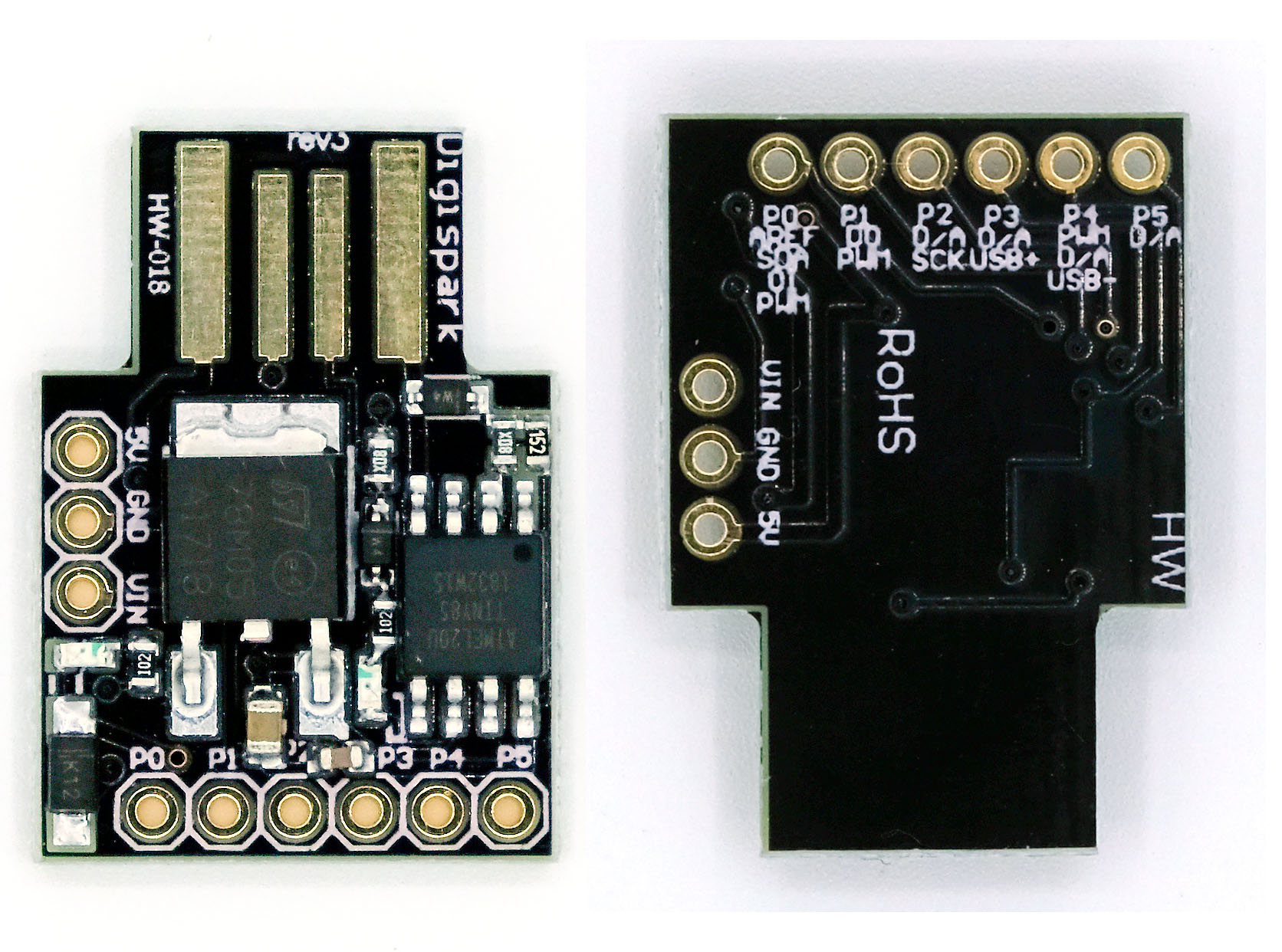
Pinout of the Digispark
-
P0: I2C SDA, PWM (“no rev”: connected to the on-board LED)
-
P1: PWM (Rev2, 3, 4: connected to the on-board LED)
-
P2: I2C SCK, analog in
-
P3: analog in, USB+
-
P4: PWM, analog in, USB-
-
P5: analog input (this pin provides 3V when it is HIGH!)
This is very similar to the ATtiny85 pinout, which is not surprising, since the Digispark is based on it.

Different versions of the Digispark
There are several versions of the Digispark. Revisions 2, 3, and 4 have a corresponding marking on the USB connector (revx). On these versions, the on-board LED is connected to P1, meaning it lights up when P1 is HIGH. On boards without a revision number, P0 is connected to the on-board LED. If you have this version, you must desolder the LED or cut the connection to the LED if you would like to work with I2C. More details are available here.
According to Digistump, Revision 3 is a counterfeit that you really shouldn’t buy, even though it works in principle. On the other hand, Revision 3 is so widespread that it’s difficult to find any other version. And so I ended up buying this version myself. It has only one drawback: P5 is configured as a reset pin on this model and therefore cannot be used as an I/O pin without further modification. Give it a try if you have a “rev3.” Launch a sketch and briefly connect P5 to GND — the Digispark will reboot. Accordingly, the Blink sketch below won’t work with P5 either. In the last section of this post, I’ll explain how to fix this issue and turn P5 into an I/O pin.
To add to the confusion, there are also versions without a revision number that are not original Digistump products. I came across one such unit, and it worked just like “rev3”.
Setting up the Arduino IDE for Digispark
Even though working with the Digispark is very easy, you still need to do a little setup first. But that only takes a few minutes. I’m assuming you’re using an Arduino IDE version >= 1.6.6.
Step 1: Driver installation
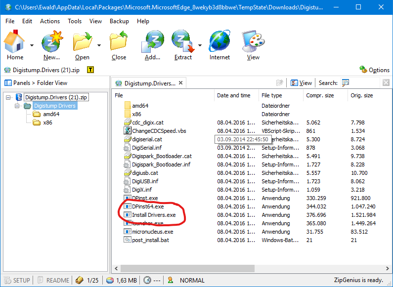
You can download the driver installer here. If, like me, you use Windows, click the highlighted link on the page:

Unzip the file and run “Install Drivers.exe” for a 32-bit system or “DPInst64.exe” for a 64-bit system:
Step 2: Enter board manager URL
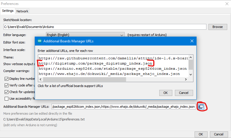
Then open the Arduino IDE and enter the board manager URL
“http://digistump.com/package_digistump_index.json”
in the preferences:
Step 3: Install the Digistump package
Then you go to
Tools -> Board: xxxx -> Boards Manager
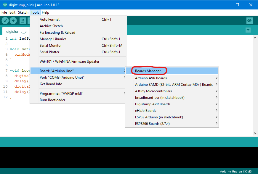
… and search for “digistump,” install the package, and restart the Arduino IDE. That’s all there is to it.

Uploading the first sketch
For testing purposes, I’m using a simple blink sketch. It’s no different from a blink sketch for Arduino boards. When using “digitalWrite”, the pins are addressed according to their “P-number.” That is: 0 is P0, 1 is P1, 2 is P2, and so on. It may sound trivial at this point, but it’s different with “analogRead”.
int ledPin = 1;

void setup() {
  pinMode(ledPin, OUTPUT);
}

void loop() {
  digitalWrite(ledPin, HIGH);
  delay(1000);
  digitalWrite(ledPin, LOW);
  delay(1000);
}
As for the circuit: it doesn’t get any simpler than this. Connect the LED to GND or P1. The Digispark is connected to the PC via USB, but only after you’re prompted to do so during the upload (this will become clearer in a moment).

In the Arduino IDE, select “Digispark (Default – 16.5 MHz)”. However, the versions labeled “no USB” and those with different clock speeds also work. The “Port” option is grayed out. Don’t worry — that’s normal, even if the Digispark is plugged in.

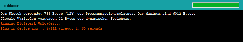
If you upload the sketch now, you’ll see the following message:
Now connect the Digispark via USB, and — if all goes well — you’ll see the following message:
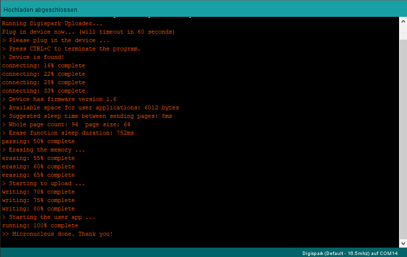
The LED should now be flashing as well. If you have a Digispark model from revision 2, 3, or 4, the on-board LED will also be flashing, since we selected P1 as the ledPin.
You can use the other five pins for this sketch in the same way, with the caveat that P5 will supply 3 volts instead of 5 volts, or won’t work at all if you’re using Revision 3 or other clones.
Slow booting
It’s surprising that the Digispark takes a full five seconds to start the sketch after powering on. An ATtiny85 with the standard bootloader is faster. In my post about radio power sockets and handheld transmitters, I presented a DIY handheld transmitter based on an ATtiny85. The wireless button was a pushbutton that supplied power to the ATtiny85, thereby launching the wireless sketch. If I were to build the same thing with the Digispark, I’d have to hold down the wireless button for at least five seconds, which wouldn’t be particularly user-friendly. Admittedly, though, such an application is more of an exception, so in most cases this boot time shouldn’t be a major issue.
Analog Read with the Digispark
Analog read is supported on pins 2, 3, 4, and 5. However, it is confusing that, unlike with digital read, the physical pin number does not match the analog read number. The Digispark inherited this behavior from the ATtiny85, which operates in the same way. The mapping is as follows:
- P2: analogRead(1)
- P3: analogRead(3)
- P4: analogRead(2)
- P5: analogRead(0)
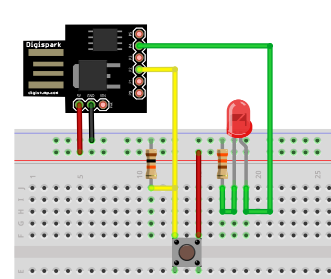
In my simple example, the voltage at P2 is checked. If it exceeds a certain value, an LED at P4 lights up. Here’s what the sketch looks like:
int ledPin = 4;
int analogInPin2 = 1; // analogRead(1) erfolgt an P2

void setup() {
  pinMode(ledPin, OUTPUT);
}

void loop() {
  if(analogRead(analogInPin2)>100){
    digitalWrite(ledPin, HIGH);
  }
  else{
    digitalWrite(ledPin, LOW);
  }
}
Here is a simple test circuit for that:
I2C with the Digispark
As mentioned earlier, I2C devices can be controlled directly using the Wire library, which is an advantage over the ATtiny85. As an example, I have chosen to control the MCP23017 port expander. The yellow wire on P0 is SDA, and the green wire on P2 is SCL. These are connected to the corresponding SDA and SCL pins on the MCP23017. The 4.7 kΩ pull-up resistors on the I2C lines are important.
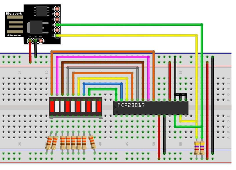
For the sake of completeness, here’s a sample sketch (if you’d like to read more about the MCP23017, you can find a post I wrote about it here).
#define MCP_ADDRESS 0x20 // (A2/A1/A0 = LOW)
#include <Wire.h>
#include <MCP23017.h> // meine MCP23017 Bibliothek
MCP23017 myMCP(MCP_ADDRESS,5); // 5: Reset - brauchen wir hier nicht
int wT = 1000; // wT = waiting time

void setup(){
  Wire.begin();
  myMCP.Init();
  myMCP.setPortMode(B11111111, A);
  delay(wT);
}

void loop(){
  myMCP.setAllPins(A, ON);
  delay(wT);
  myMCP.setAllPins(A, OFF);
  delay(wT);
  myMCP.setPin(0, A, ON);
  delay(wT);
  myMCP.setPin(4, A, ON);
  delay(wT);
  myMCP.setPin(7, A, ON);
  delay(wT);
}
Turning P5 into an I/O pin
With the ATtiny85, only 5 pins can generally be used as I/O pins. Pin 1 (PB5, RESET) of the ATtiny85 can only be used as an I/O pin indirectly. The problem is that doing so disables the reset function, meaning the ATtiny85 can no longer be easily reprogrammed. You effectively lock yourself out, so to speak. This can also be resolved, but only with programmers that have a high-voltage function.
With the Digispark, you don’t need the reset function on P5, since programming is done via USB. This leaves you with 6 I/O pins available. The manufacturers of Revision 3 and other clones, on the other hand, have retained the reset function on P5. If you only need 5 pins or perhaps want to use the reset function, then leave everything as is. If, on the other hand, you want to use all pins as I/O pins, you can change this by following these instructions.
To enable the P5 as an I/O pin or disable the reset function, the corresponding fuse bit (RSTDISBL) must be “enabled.” I’d like to present two ways to do this.
Option 1: With WinAVR and Arduino UNO
The great thing about this method is that most people have an Arduino UNO (the Nano, Pro Mini, etc. work too), and the required software, WinAVR, is free.
First, download the WinAVR program (for example, from here) and install it.
Next, upload the ArduinoISP sketch from the examples to the Arduino. This will turn the Arduino into a programmer.

Then connect the Digispark to the Arduino as follows:
- P0 –> 11
- P1 –> 12
- P2 –> 13
- P5 –> 10
Schließlich verbindet ihr noch GND mit GND, 5V mit 5V und setzt einen 10 µF Kondensator zwischen den Arduino Reset und GND (Polarität beachten: Minus des Kondensators an GND).

Next, open a terminal window on your PC. Depending on whether you’ve set the system paths, you may need to navigate to the directory where you installed WinAVR. Enter the following, replacing COM14 with the port your Arduino is connected to:
avrdude -P COM14 -b 19200 -c avrisp -p attiny85 -n
Press Enter to confirm, enter the next line, and press Enter again to confirm:
avrdude -P COM14 -b 19200 -p attiny85 -c avrisp -U hfuse:w:0x5F:m
If everything goes well, you should see messages similar to this one:

Now you can upload the Blink sketch from earlier to P5 as an LED pin — the LED will now blink. It’s just a little less bright than on the other pins, since P5 only supplies 3 volts.
Option 2: with Atmel Studio and suitable programmer
What you need
This method is less cryptic, but it requires installing the fairly large — though free — Atmel (Microchip) Studio software package (currently version 7). You’ll also need a compatible programmer. You can download Atmel Studio 7 here. Anyone who wants to delve deeper into programming Atmel microcontrollers at the register level and in “C” should familiarize themselves with this program anyway. Just to change a single fuse bit, it’s a bit of an overkill to download this powerful tool onto your hard drive. In a later post, I’ll go into more detail about Atmel Studio.
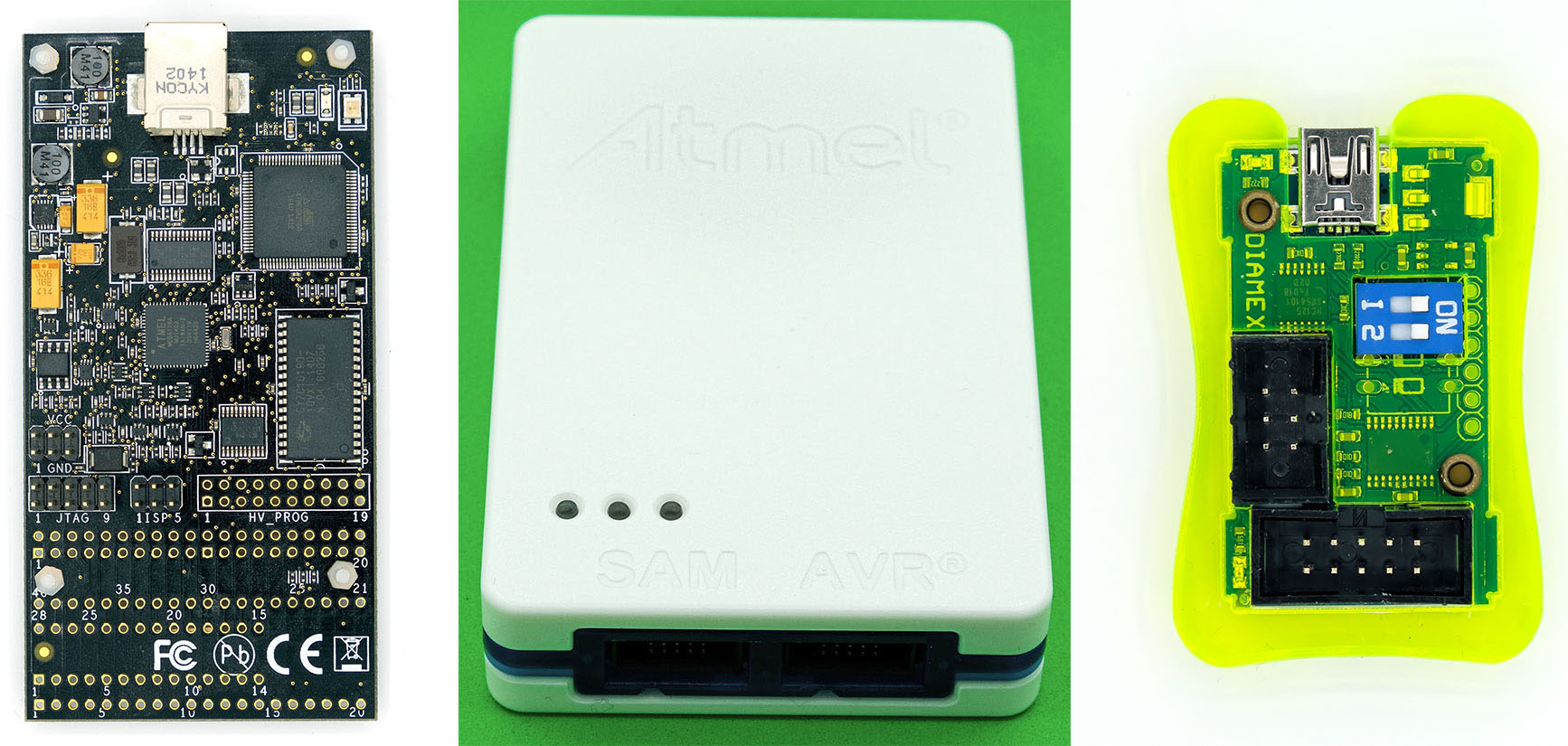
Programmers for Atmel Studio are relatively expensive. One of the more affordable options is the USB ISP programmer from Tremex/Diamex, which you can buy for about 20 euros—for example, here on Amazon. I’ve tried it out, and it works perfectly with Atmel Studio. If you’re using Windows 10, you don’t even need to install a driver.
Better, but also more expensive, are the AVR Dragon and the Atmel-ICE. The former is available for 50–80 euros, while the latter starts at 120 euros. Both models also support debugging. In addition, the Dragon supports HVSP (High Voltage Serial Programming), which allows you to reverse the modifications made to the P5. The Atmel-ICE cannot do this, but it comes in a sleek case.
If you’re investing in a programmer, I recommend getting a breadboard adapter like this one right away:
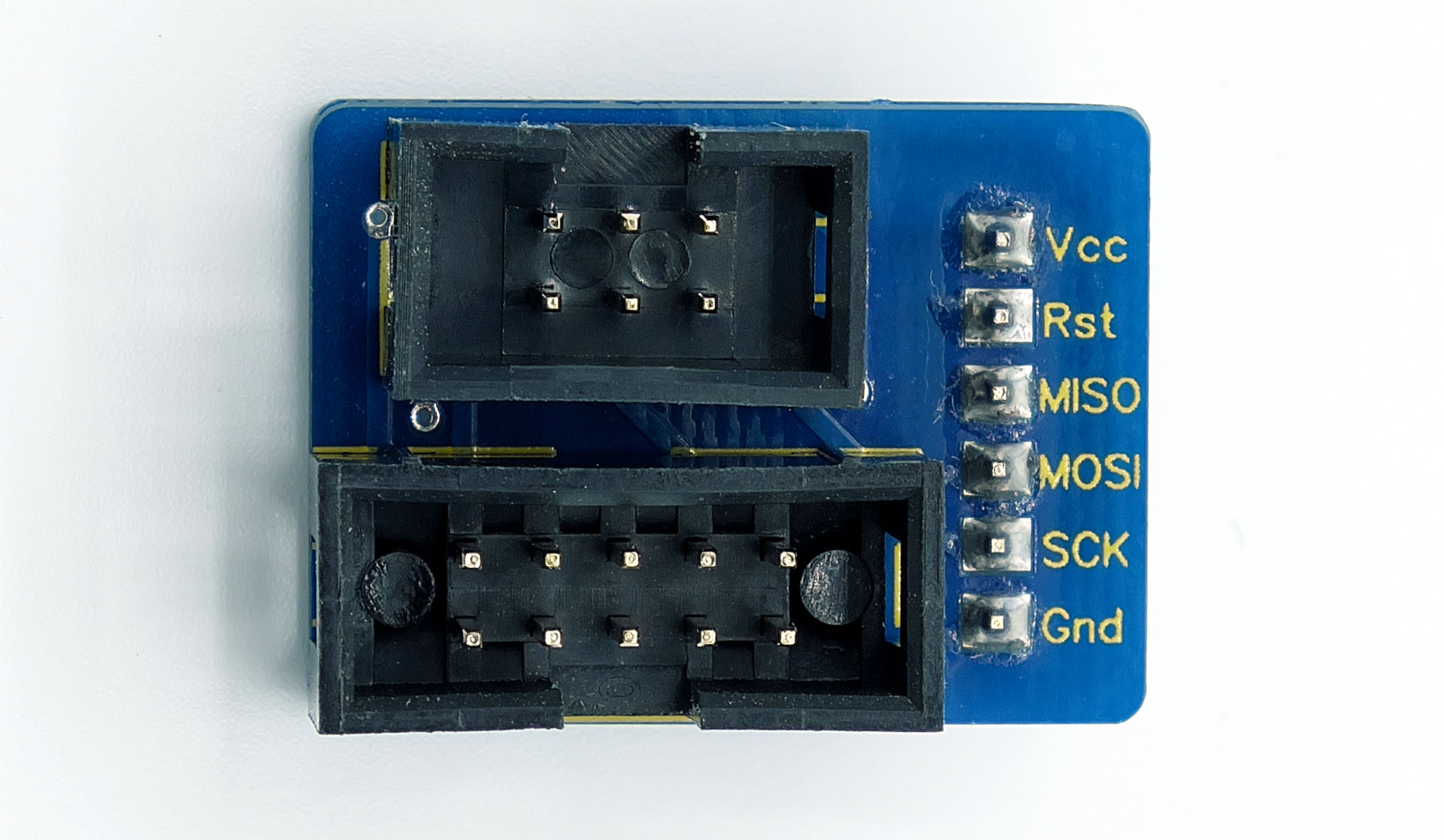
It makes the job easier and helps prevent wiring errors. You can buy one here, for example, or one with two 3-pin headers here.
Wiring
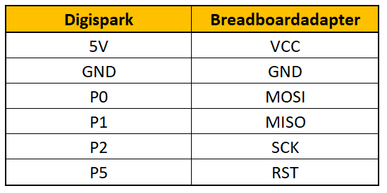
The connection diagram for the programmer and Digispark is as follows:
Please note that the AVR Dragon cannot power the Digispark. You will need a separate power source. The inexpensive USB ISP programmer, on the other hand, can do this, provided that DIP switches 1 and 2 are set to “ON.”
Using Atmel Studio 7
If you’re using a Dragon or Atmel ICE, Atmel Studio should detect them automatically. You’ll first need to integrate the Tremex/Diamex USB ISP programmer. To do this, go to the menu and select
Tools –> Add Target… –> Select Tool
Select STK500 and the port, then click “Apply”.
In the menu bar, you’ll find a small icon for “Device Programming”. Click on it.

If the tool isn’t already selected in the next window, select it from the drop-down menu here. Select ATtiny85 as the device. The interface is ISP. Then click “Apply”.
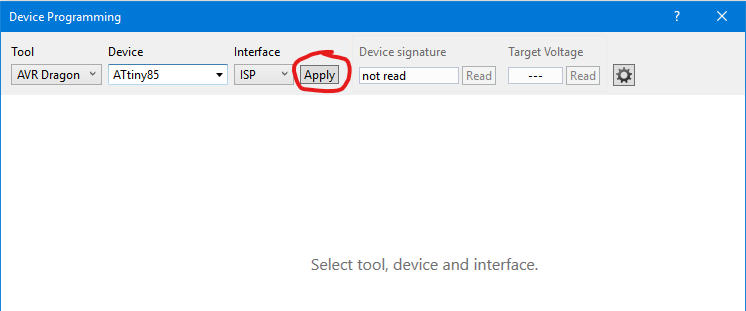
You can then check the supply voltage and verify that the correct signature is present. It should be 0x1E930B. Now go to the “Fuses” menu item.
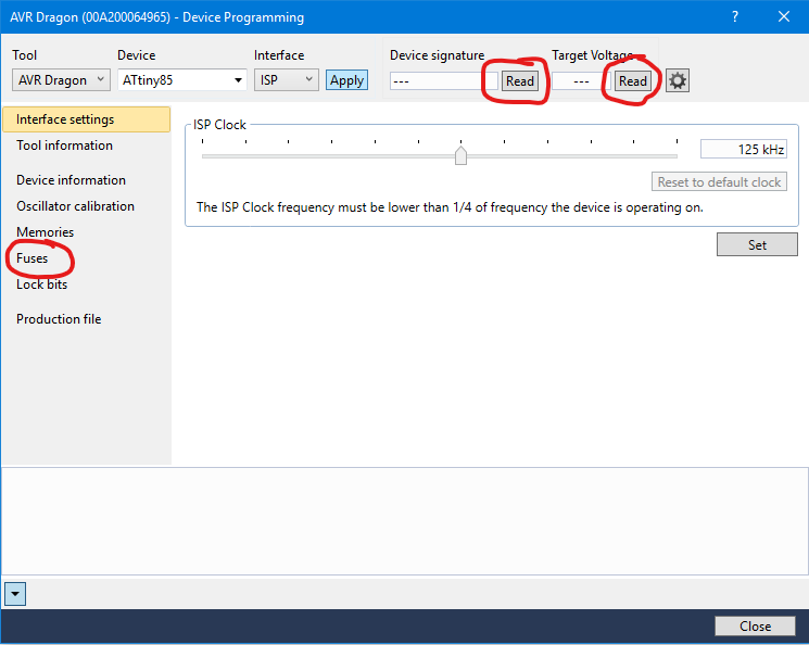
Check the box next to “HIGH.RSTDISBL,” click “Program,” and then click “Continue” in the warning window that pops up. If everything went well, you should see “Verify Registers … OK” at the bottom of the message log.
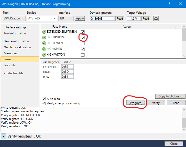
P5 should now be ready for use as an I/O pin.
If you’d like to learn more about Atmel Studio 7, stay tuned — I’ll be posting an introduction in one of my next articles.