What is it all about?
Many radio-controlled devices such as garage doors, window sensors, radio sockets and hand transmitters are based on 433 MHz technology. In my last post I showed how to send data from one Arduino to another with transmitter and receiver modules. In this article I show how an Arduino can communicate with the above devices. Using the example of radio sockets and the RCSwitch library, I explain the principle and at the end I present a self-built hand-held transmitter.
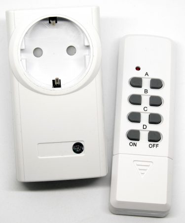
Radio socket sets
Radio sockets are usually offered as a set consisting of one transmitter and several sockets. Such sets are available for 10 to 30 euros in electronics stores or online shops. There are sockets that can “learn” on/off signals and others for which you can adjust the channels via dip switches (in German language also known as “Mäuseklavier” = “mouse piano”). Both versions can be controlled with the Arduino, but I advise to take those with dip switches, as they are more flexible.
Setting without Arduino (just hand transmitter to socket)
On the transmitter side, the coding is set with the dip switches 1 to 5. This must match the coding at the power outlet. The dip switches A to E determine which transmitter button the socket “listens” to, in this case B. The setting shown here is used in all other explanations and examples.

The RCSwitch Library
We don’t want to use the set as such, but either control an Arduino with the transmitter or control a radio socket with an Arduino. If you don’t want to get into the depths of signal transmission, you first need a library. For this post I have chosen the RCSwitch library. To install, simply follow the link, download as a zip file and unzip it in the Arduino\libraries directory.
The hardware
I use the modules presented in my last post (see below). For details just go back to the post. It’s as simple as that: in order to attach the transmitter and the receiver to the Arduino, GND is connected to GND, VCC with 5 V and the data pin depending on the specification from the sample sketches. Don’t forget the antennas, which may still need to be soldered to the modules.

Here we go
Use of dip switch systems
To control the wireless socket by the transmitter module, simply adjust the sample sketch “TypeA_WithDIPSwitches.ino” from the RCSwitch library according to the dip switch setting. The sketch is self-explanatory. And that’s it! If everything is set up correctly, the radio socket should be switched on and off with this example every one second.
/*
 Examples of sockets which are configured with a 10 pole DIP switch.

 https://github.com/sui77/rc-switch/
*/

#include <RCSwitch.h>

RCSwitch mySwitch = RCSwitch();

void setup() {

  // Transmitter is connected to Arduino Pin #10
  mySwitch.enableTransmit(10);

  // Optional set pulse length.
  // mySwitch.setPulseLength(320);

}

void loop() {

  // Switch on:
  // The first parameter represents the setting of the first 5 DIP switches.
  // In this example it's OFF-ON-OFF-ON-ON.
  //
  // The second parameter represents the setting of the last 5 DIP switches.
  // In this example the last 5 DIP switches are OFF-ON-OFF-OFF-OFF.
  mySwitch.switchOn("01011", "01000");

  // Wait a second
  delay(1000);

  // Switch off
  mySwitch.switchOff("01011", "01000");

  // Wait another second
 delay(1000);

}
Use of other systems without dip switches
Analyzing the radio code
For other systems (i.e. those without dip switches) you first have to find out the radio code. For this purpose, use the receiver module, the transmitter from the set and preferably the sample sketch “ReceiveDemo_Advanced.ino”. Make sure that the data pin of the receiver module is connected to pin 2 of the Arduino.
/*
 Example for receiving

 https://github.com/sui77/rc-switch/

 If you want to visualize a telegram copy the raw data and
 paste it into http://test.sui.li/oszi/
*/

#include <RCSwitch.h>
static const char* bin2tristate(const char* bin);
static char * dec2binWzerofill(unsigned long Dec, unsigned int bitLength);

RCSwitch mySwitch = RCSwitch();

void setup() {
  Serial.begin(9600);
  mySwitch.enableReceive(0); // Receiver on interrupt 0 => that is pin #2
}

void loop() {
  if (mySwitch.available()) {
  output(mySwitch.getReceivedValue(), mySwitch.getReceivedBitlength(),mySwitch.getReceivedDelay(), mySwitch.getReceivedRawdata(),mySwitch.getReceivedProtocol());
  mySwitch.resetAvailable();
  }
}

void output(unsigned long decimal, unsigned int length, unsigned int delay, unsigned int* raw, unsigned int protocol) {

  const char* b = dec2binWzerofill(decimal, length);
  Serial.print("Decimal: ");
  Serial.print(decimal);
  Serial.print(" (");
  Serial.print( length );
  Serial.print("Bit) Binary: ");
  Serial.print( b );
  Serial.print(" Tri-State: ");
  Serial.print( bin2tristate( b) );
  Serial.print(" PulseLength: ");
  Serial.print(delay);
  Serial.print(" microseconds");
  Serial.print(" Protocol: ");
  Serial.println(protocol);

  Serial.print("Raw data: ");
  for (unsigned int i=0; i<= length*2; i++) {
    Serial.print(raw[i]);
    Serial.print(",");
  }
  Serial.println();
  Serial.println();
}

static const char* bin2tristate(const char* bin) {
  static char returnValue[50];
  int pos = 0;
  int pos2 = 0;
  while (bin[pos]!='\0' && bin[pos+1]!='\0') {
    if (bin[pos]=='0' && bin[pos+1]=='0') {
      returnValue[pos2] = '0';
    } else if (bin[pos]=='1' && bin[pos+1]=='1') {
      returnValue[pos2] = '1';
    } else if (bin[pos]=='0' && bin[pos+1]=='1') {
      returnValue[pos2] = 'F';
    } else {
      return "not applicable";
    }
    pos = pos+2;
    pos2++;
  }
  returnValue[pos2] = '\0';
  return returnValue;
}

static char * dec2binWzerofill(unsigned long Dec, unsigned int bitLength) {
  static char bin[64];
  unsigned int i=0;

  while (Dec > 0) {
    bin[32+i++] = ((Dec & 1) > 0) ? '1' : '0';
    Dec = Dec >> 1;
  }

  for (unsigned int j = 0; j< bitLength; j++) {
    if (j >= bitLength - i) {
      bin[j] = bin[ 31 + i - (j - (bitLength - i)) ];
    } else {
        bin[j] = '0';
    }
  }
  bin[bitLength] = '\0';

  return bin;
}
After starting the sketch and pressing the selected send button, you get the following message for “ON” and “OFF” on the serial monitor (if the transmitter is set as shown above and using channel B):

This is the respective radio code in decimal, binary or tristate format. In the tristate format, you see the dip switch setting by replacing “F” with “OFF” and “0” with “ON”. The last “0F” or “F0” means power on or off, respectively. In binary code, “01” and “00” represent “OFF” or “ON” (not really important, but maybe interesting).
Then write down the code for switching on and off in one of the formats.
Sending the radio code
For sending this radio code by means of a transmitter module, we take a look at the sample sketch “SendDemo.ino”, which I have already adapted for our sample transmitter:
/*
 Example for different sending methods

 https://github.com/sui77/rc-switch/

*/

#include <RCSwitch.h>

RCSwitch mySwitch = RCSwitch();

void setup() {

  Serial.begin(9600);

  // Transmitter is connected to Arduino Pin #10
  mySwitch.enableTransmit(10);

  // Optional set protocol (default is 1, will work for most outlets)
  // mySwitch.setProtocol(2);

  // Optional set pulse length.
  // mySwitch.setPulseLength(320);

  // Optional set number of transmission repetitions.
  // mySwitch.setRepeatTransmit(15);

}

void loop() {

  /* See Example: TypeA_WithDIPSwitches */
  mySwitch.switchOn("01011", "01000");
  delay(1000);
  mySwitch.switchOff("01011", "01000");
  delay(1000);

  /* Same switch as above, but using decimal code */
  mySwitch.send(4460881, 24);
  delay(1000);
  mySwitch.send(4460884, 24);
  delay(1000);

  /* Same switch as above, but using binary code */
  mySwitch.send("010001000001000101010001");
  delay(1000);
  mySwitch.send("010001000001000101010100");
  delay(1000);

  /* Same switch as above, but tri-state code */
  mySwitch.sendTriState("F0F00F0FFF0F");
  delay(1000);
  mySwitch.sendTriState("F0F00F0FFFF0");
  delay(1000);

  delay(5000);
}
For illustration all sending methods are used in the above example. Of course, you only need one of them.
Hand transmitters

Hand transmitter
Most of the time you will want to control a radio socket with a transmitter module. If you want to send signals to your Arduino with the transmitting unit, you can buy just a hand transmitter (i.e. without a set) like the one shown above. I found a really cool “hardware hack” with exactly this transmitter here. There it is described how to convert the hand transmitter with a motion detector into a wireless motion detector, which does not need another Arduino or microcontroller on the transmission side. I have tried it and it works fine.
A self-made hand transmitter
Then I wanted to build a hand transmitter myself. My goal was to construct it as minimalistic as possible. Above all, I didn’t want to add an extra on/off switch for the microcontroller besides the send button, because hand held transmitters that you can buy usually do also not have an on/off switch. The result is the following:
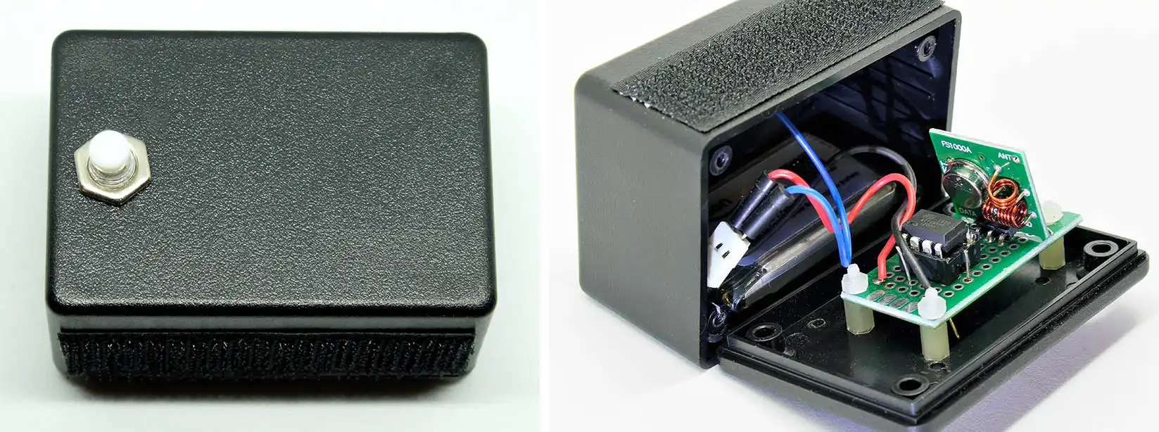
Only a pushbutton, an ATtiny85, a simple transmitter module and a 3.7 V Li battery from drone construction were used as electrical components. You may notice that no antenna has been used. Depending on the quality of the receiving device and the desired distance, this is might not be necessary.
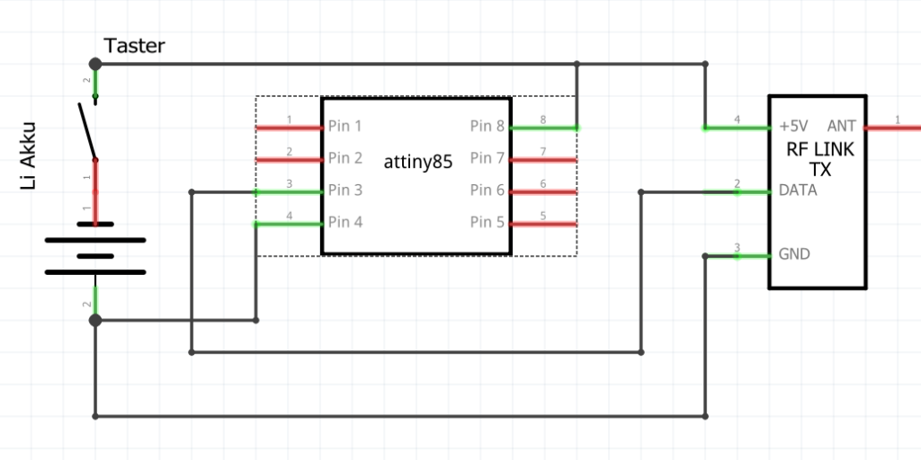
How can you get by with just one button? Quite simple: it’s a question of timing. Pressing the button starts the power supply and thus the sketch. After a few fractions of a second, the “On” signal is sent. To be on the safe side, I send the signal three times. If I want to send an “off” signal, I just stay on the button for another second, otherwise I’ll just let go. Here is the simple sketch:
#include <RCSwitch.h>

RCSwitch mySwitch = RCSwitch();

void setup() {
  mySwitch.enableTransmit(4);
  mySwitch.setPulseLength(311);
  delay(10);
}

void loop() {
  mySwitch.send("010001000001000101010001");
  delay(5);
  mySwitch.send("010001000001000101010001");
  delay(5);
  mySwitch.send("010001000001000101010001");
  delay(1000);
  mySwitch.send("010001000001000101010100");
  delay(5);
  mySwitch.send("010001000001000101010100");
  delay(5);
  mySwitch.send("010001000001000101010100");
  delay(5);
  delay(5000);
}