For me, wireless data transmission is one of the most exciting areas in the world of microcontrollers. Essentially, there are the following techniques:
- Bluetooth
- W-Lan
- Infrared
- Radio (433 MHz, 868 MHz, 2.4 GHz)
Strictly speaking, Bluetooth and W-Lan are of course also radio technologies. However, they enjoy a special position due to their special transmission protocols. This article is about the 433 MHz radio technology. I will limit myself to the “one-way” technique, i.e. simple transmitter / receiver systems. In detail, the following is discussed:
- the required modules
- Antennas
- installation of a suitable library
- a minimal setup
- Experience with different receiver modules
In a separate post I introduce the HC-12 module. This is extremely easy to handle, and it can communicate in two ways. Here is the link to the post. The only disadvantage of the HC-12 module is its inability to communicate with radio sockets or hand transmitters.
Common modules
What do you need for the 433 MHz radio with the Arduino? First of all, suitable radio modules. If you are looking for it at Amazon, for example, you will especially come across the following combination of a receiver and a transmitter. It is offered without a detailed type designation in many shops:
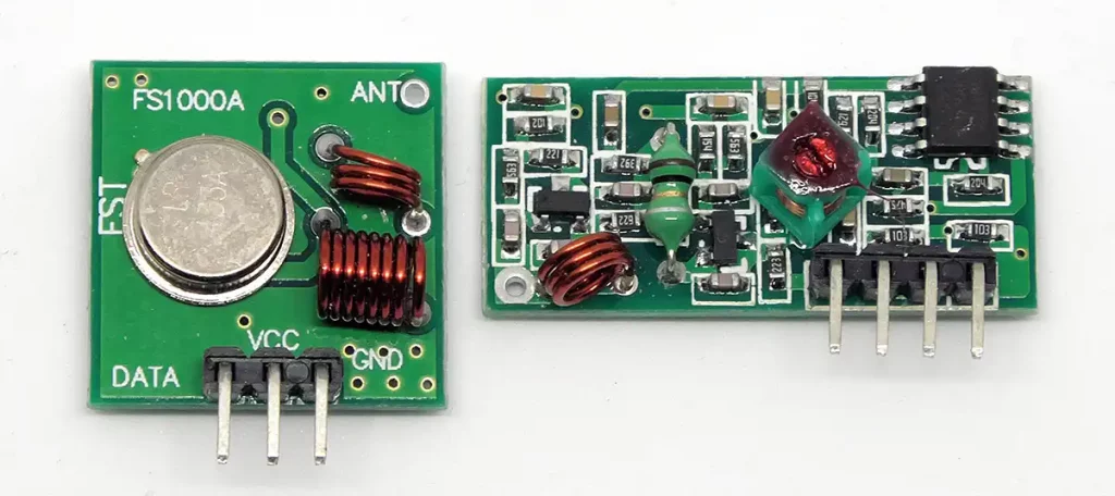
These parts are extremely cheap and, in my (recent) experience, better than their reputation. I had also bought some of them where the receiver modules could hardly be used. Maximum two meters of transmission. After that experience, I was fed up with these parts for quite some time. But recently I bought some of them again just to use the transmitter modules. And behold: now also the receiver modules worked wonderfully. Many negative comments can also be found from people who have not used an antenna, but even more.
In building technology there are a number of other transmitters and receivers on a 433 MHz basis, such as window sensors and radio sockets. I will discuss the latter in a later article.
Antenna
Without an antenna, (almost) nothing works. If you buy a transmitter – Receiver Duo as shown above and use it without an antenna, then you will be very disappointed. You just get radio lines across the desk. Beyond that distance it does not work. Antennas must therefore be attached. In my experience, that’s extremely important for the transmitter module, but better to have an antenna on both modules.
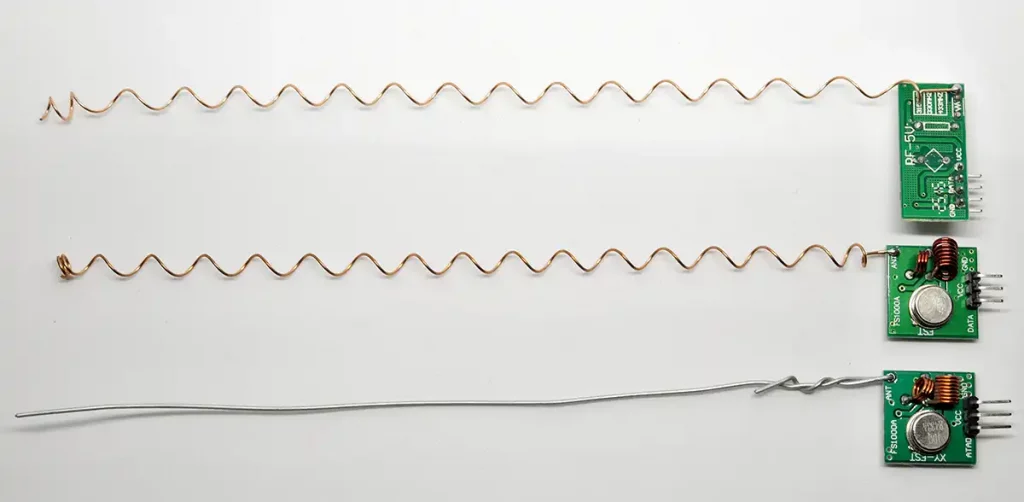
The length of the antenna should be a quarter of the wavelength. The wavelength is the speed of light divided by frequency. The result divided by 4 is 17.3 cm. There are many instructions in the net for self-building of good antennas, e.g. here. In my experience, however, you can also achieve good ranges if you solder a simple wire. So, you don’t have to make science out of it. It’s different of course if you really reach the limits of the range.
Small spiral antennas are also offered or modules that have already been soldered. I can only give limited advice on this. The transmission is better than without, but a long wire works simply better. If you use such spiral antennas and have problems with the range, you can also pull them apart and thus, in my experience, achieve a better result. So here are a few – admittedly not nice – but pragmatic and working solutions:
The control
There are a number of libraries for controlling radio modules using Arduino. I had been using the VirtualWire library for a long time, but apparently this is no longer maintained. I would like to recommend the RadioHead library written by Paul Stoffregen as it is compatible with many radio modules. How to develop your own radio protocol, I will explain in another post.
Installing the RadioHead Library
For the less experienced: Follow the above link, go to “Clone or Download”, select “Download ZIP” and unpack the Zip file in the directory “Arduino-libraries”. Afterwards you should find there a folder called RadioHead-master. The Zip file can now be deleted. If you look into the RadioHead-master directory, you will see that it is a collection of libraries.
Adaptation of the sample sketches
The “RH_Ask” library is suitable for the simple radio modules used here. The easiest way to start is to take the included sample sketches and modify them if necessary. For the transmitter, this is the file “RadioHead-master\examples\ask\ask_transmitter\ask_transmitter.pde”, which is called directly from the Arduino IDE, edited if necessary, and saved in its sketches. For the receiver, you choose the example “ask_receiver.de”.
Here is my adaptation of the transmitter sketch:
The example sketches are actually self-explanatory, but in the original there was no indication of the meaning of the parameters in object initialization:
- speed: Data transfer in bits/s
- rxPin: Data pin for the receiver
- txPin: Data pin for the transmitter
- pttPin: “Enable” pin for the transmitter (we don’t need this for our simple modules)
- pttInverted: optional parameter for pttPin logic, default: false
So in my adjustment of the transmitter sketch, I set the txPin to 8. rxPin and pttPin are meaningless here, speed remains unchanged. In the sketch for the receiver you set the rxPin accordingly.
The wiring
Connections
The transmitter can be operated with 3.3 to 12 V, the receiver needs 5 V. In my experimental setup I operate both with 5V. On the transmitter side I used an Arduino Nano (I also like the ProMini) and on the receiver side an Arduino UNO. Only the transmitter side is shown here:
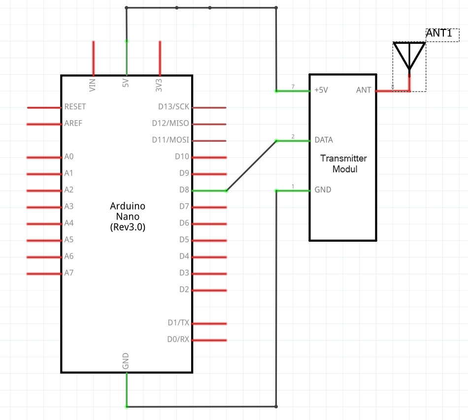
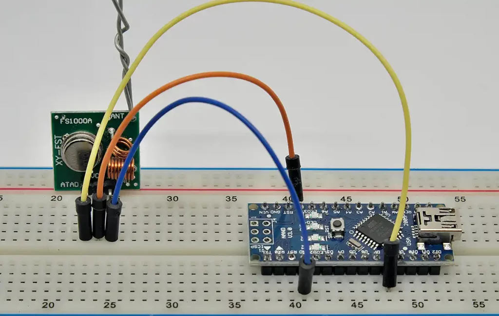
Correspondingly, one proceeds on the receiver side. Now you are ready to go. If everything worked out, you should now be able to read your message on the receiver side using a serial monitor. You can’t really do much wrong, therefore I don’t add a troubleshooting section here.
Experience with alternative receiver modules
Finally, I want to share my experience with various receiver modules. The receiver modules shown below with the designation “RXB6”, “RXB8” and “RXB12” compete against the module from the combi pack. These modules are also available for a few euros.

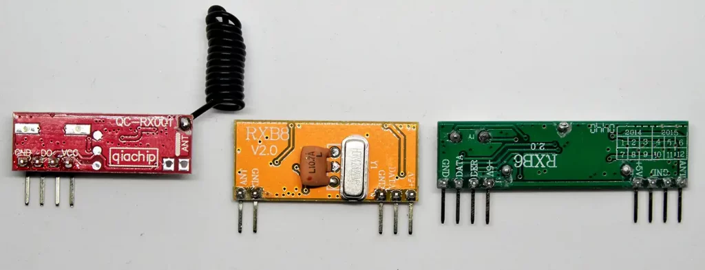
The trial
First, I attached the same kind of antenna to all receiver modules. For this purpose I removed the original spiral antenna on the RXB12. The receiver module was attached to the Arduino UNO and the UNO was connected to the PC. The transmitter module (from the combi pack) was placed on a breadboard and attached to the Arduino Nano (battery operation). Then I placed the transmitter in different places in the house and checked if the transmission path was working.
The result
- In the same room (approx. 6m) no problem for all modules
- In the neighboring room (closed door, massive wall) the RXB6 and RXB12 already had problems in some places.
- The module from the combi pack and the RXB8 had a good connection across the house through several walls and over one floor. For comparison: the router in my house needs a repeater although it’s placed centrally.
- The big surprise was that the RXB8 even worked without an antenna(!).
On a scale from 0 to 10 I would rate the modules as follows:
- RXB12: 2
- RXB6: 3
- Combi pack module: 7
- RXB8: 10+
Since the RXB8 has such a good reception without an antenna, it can be installed particularly well in small housings.
And what is your experience with different modules? I would be pleased to receive any comments.
This is realy interesting and informative website. Thank you Wolfgang.
Best regards, Sasha
Thank you for the feedback!
Hallo Wolle, jetzt auch auf Englisch – Respekt! Helene.
Danke, leider haben anscheinend alle Abonnenten eine Benachrichtigung über die Veröffentlichung der englischen Version dieses älteren Beitrages bekommen. Ich versuche, das abzustellen.