
General comments
If you want to immortalize your project firmly in wire and solder, you usually don’t do this using an Arduino UNO, but choose either an ATtiny or ATmega microcontroller or a small board such as the Arduino Nano or the Arduino Pro Mini which is described here. I will first talk about the different versions of the Pro Mini, then about the sketch upload using the USB-to-TTL module and finally focus on trouble shooting. Programming of the Arduino Pro Mini is very convenient!
Various versions
First, there are four different versions of the microcontroller used, the operating voltage and the clock rate:
- ATmega 328P, 5 V, 16 MHz
- ATmega 328P, 3.3 V, 8 MHz
- ATmega 168, 5 V, 16 MHz
- ATmega 168, 3.3 V, 8 MHz
If you have developed your project with the UNO, then the 328P / 5V variant is most suitable, as full compatibility is guaranteed. If you use 3.3 V components such as certain sensors, the 3.3 V variant can also be of interest for you. I myself have only tried 328P /5V models. At Amazon you get the boards for roughly 3 Euros.
In addition, the boards differ partly in the layout, especially in the position of the pins A4 (SDA) and A5 (SCL), which are required for the I2C communication. For the models shown above, they are located at the narrow end next to the reset button (left model) and above A2 and A4 (right model). Unfortunately, with both models you can’t conect A4 and A5 directly to a PCB circuit board. Why they don’t stick to the grid measure is a mystery to me.
Practical power supply
Very convenient is that you can operate the Pro Mini via the raw input with voltages between 5 and 12 V. Regardless of the exact supply voltage, I measured stable 5 V at the VCC pin. For example, it is suitable to operate the board with a 9 V block battery. You can also connect a 5 V power supply source directly to the VCC pin, but it should be a regulated one.
Sketch upload via Arduino IDE
For the Sketch Upload you need a USB-to-TTL converter module like one of the models shown here:
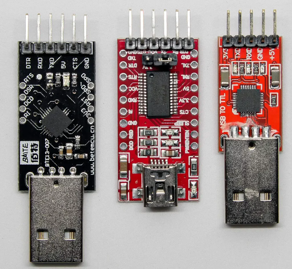
You can get these modules e.g. at Amazon for 5 to 10 Euro. They differ essentially in the format of the USB port, in the output voltage (3.3 and / or 5 V) and in the presence or absence of a DTR (Data Terminal Ready) pin. It’s more comfortable to use the ones with DTR pin as you’ll see soon. In addition, the modules use different chips, e.g. FT232, CP2102 or CH340G. If everything works, you may still need a driver. They can be found on the net without any problems. You can check the operational readiness of the module in the device manager of your Windows. Here, for example, everything is OK:

Upload with DTR
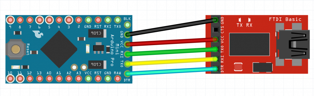
First, the Arduino Pro Mini is connected to the USB-to-TTL module as shown:
Then in the Arduino IDE:
- choose the right port which is connected to USB-to-TTL module
- choose “Arduino Pro or Pro Mini” as board
- Choose the right variant
- Select and upload the sketch – and that’s it.

Upload without DTR
You have to reset the Pro Mini before the upload. This is exactly what the DTR connection does. If you don’t have one, you have to reset manually using the reset button on the Pro Mini. It is not important when you press the button, but the decisive factor is when you release it. For this purpose choose “Upload” in the Arduino IDE, wait until the compilation is finished and release the reset key when it wants to upload (this is when the message in white font appears):

And if I don’t have a USB-to-TTL module?
This also works, if you have an Arduino UNO. Description can be found here. But I would recommend to invest in a USB-to-TTL module. This is standard equipment you should have anyway.
Help! – troubleshooting
There are endless possibilities for errors. The cause can of course be best defined if you know the error message. But here are some general aspects that you can always check:
- Check the installation of the module
- Check cabling, replace cables
- Switch RX and TX, as it’s sometimes incorrectly labeled on modules
- Check the settings in the IDE
Missing, incorrect, or corrupted boot loader
When you upload from the Arduino IDE, you get the following ugly message: “avrdude: stk500_getsync(): not in sync: resp=0x00”,then it could be related to the boot loader. Don’t worry, you can burn it again and it’s like this:
- Connect your Arduino UNO to the PC
- in the Arduino IDE select: File – Examples – ArduinoISP – ArduinoISP
- Board: Choose Arduino UNO, choose right port
- Upload
- then choose Arduino Pro Mini as a board, select the right variant
- Programmer: “Arduino as ISP” (not: ArduinoISP!)
- wire as per this scheme:

- Then select in the menu: Tools – Burn Booloader.
If it still doesn’t work, it might help to googling the error message. By the way, you will get a more detailed message when uploading, if you set the following check mark in the settings:

Important note: if you upload sketches using the ISP-method, the bootloader will be deleted. So, before changing back to the serial method (USB-to-TTL), you will have to burn the bootloader again via ISP.
Well then, have fun with the Pro Mini! Do you have any comments, additions, improvements or questions? I’m happy about any comment.
Thank you very much Wolfgang, for maintaining such a great knowledge base!
Somehow my pro mini can only receive the firmware, if I do “Upload Using Programmer” with Arduino as a programmer connected as you have explained here. USB-TTL dongles always give me “avrdude: stk500_recv(): programmer is not responding” by any means, with or without DTS, 5V or 3.3V.
Hi Dmitry, have you burned the bootloader before changing from the “Arduino as a programmer”-method (ISP) to the USB-TTL method (serial)? Every sketch upload via ISP will delete the bootloader. So, you need to bring it back before going back to the serial method. I have now added a note in the article. Another potential issue could be the RX/TX connection RX needs to be connected with TX and TX with RX. And you might check in the Windows device manager if your USB-TTL adapter is correctly installed. Is it one of these issues? If it still does not work please come back and we’ll dig deeper!
How about uploading to ATMEGA 328 on bread board using cp2102 chip? Mine does not work. Reply to lewismrm@gmail.com
Hi, can you specify “does not work”? Do you get an error message when you try to upload? Which? If you have screenshot you can send it to wolfgang.ewald@wolles-elektronikkiste.de Have you installed the driver for the cp2102? You can check in the device manager of Windows.