
About this post
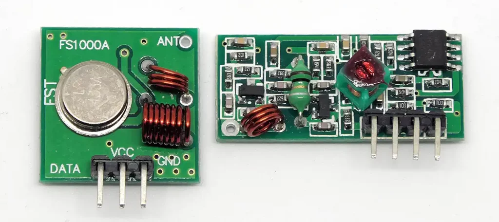
In the last articles I have explained how to control radio modules and radio sockets with the Arduino or other microcontrollers by means of suitable libraries. But does 433 MHz radio work without a library? Is it complicated to develop your own (simple) radio protocol? When you pay attention to a few things, it’s not very difficult and it’s also a lot of fun. I will present two concepts. I use simple 433 MHz transmitter and receiver modules as in the previous posts. Please do not forget to attach antennas to the modules. I probably don’t have to recreate a connection scheme for the Arduino: GND is connected with GND, VCC with 5 V and the data pin of the module is used as per the instructions in the respective sketch. For the transmitter side I used an Arduino Nano, on the receiver side a UNO.
Speed is required
Before I start, I might have to explain few things about “C”. Radio technology is so fast that the speed needed at which a pin status (HIGH or LOW) can be queried becomes quite relevant. Normally you use the digitalRead command, here e.g. to query the pin 5:
pinStatus = digitalRead(5);
The “C” spelling is synonymous, much faster, but also much more cryptic:
pinStatus = PIND & (1<<PD5);
I will perhaps go into more detail on the subject of ‘C’ in another post because there are also many other occasions where the ‘C’ spelling makes sense. Here I will only briefly explain what that means. “PD5” is a predefined constant with a value of 5 and stands for pin 5 on the PORTD of the ATmega328. This pin happens to be the digital pin 5 on Arduino. For example, the pin “PB5″ is Digitalpin 13 on Arduino. “1<<PD5” is a binary operation and means: shift the one five digits to the left. So, the 1 (00000001), is turned into 00100000.
PIND is the status register of the PORTD. If all pins are “LOW” the value of the PIND register is “00000000”. If only PD5 is “HIGH”, it is “00100000”. “&” is a binary “AND”. It compares bitwise the values on both sides. If both are the same, the result is TRUE and 1, respectively. If both are unequal, the result is FALSE or 0. And thus both of the above commands lead to the same result.
The following sketch shows that the spelling in “C” is much faster. I have queried the status of pin 5 with both commands 100000 times and measured the time required in milliseconds. Here is the sketch and the result:
unsigned long numberOfReads = 100000;
unsigned long startTime = 0;
unsigned long readTimeLength = 0;
bool pinStatus;

void setup() {
  Serial.begin(9600);
  pinMode(5,INPUT);
}

void loop() {
  startTime = millis();
  for(unsigned long i=0; i<numberOfReads; i++){
    pinStatus = digitalRead(5);
  }
  readTimeLength = millis() - startTime;
  Serial.print("digitalRead: ");
  Serial.print(readTimeLength);
  Serial.print(" ms ");
  Serial.print(" / ");
  delay(1000);

  startTime = millis();
  for(unsigned long i=0; i<numberOfReads; i++){
    pinStatus = (PIND & (1<<PD5));
  }
  readTimeLength = millis() - startTime;
  Serial.print("PIND Abfrage: ");
  Serial.print(readTimeLength);
  Serial.println(" ms");
  delay(5000);
}
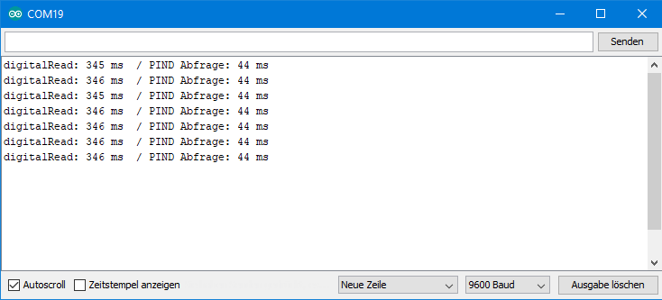
Thus, the “C” command is about eight times faster. Per single query, the result is 3.45 microseconds compared to 0.44 microseconds.
Lots of noise in the air
Actually, it sounds simple at first: On the transmitter side, a “HIGH” on the data pin leads to the sending of a signal. This creates a “HIGH” on the receiver side on the data pin and this can be evaluated in terms of time period. We are therefore not using modulation methods here. Simple, but works.
The following sketch for the receiver side captures signals and measures their duration at pin 5. To measure times, most people like to use the “millis()” or “micros()” command. Another method for measuring very short periods of time has proven its worth. In a loop, the condition for the measurement is queried. As long as the cancellation condition is not met, the sketch waits for a short time (resolution) in the loop and then a counter is incremented. In the end, counter times resolution provides the duration.
const int resolution = 5;
unsigned int counter;

void setup(){
  Serial.begin(9600);
  DDRD = 0x00; // Arduino Pins D0 - D7 as input, "C" spelling
  PORTD = 0x00; // Arduino Pins D0 - D7 are LOW, "C" spelling
 }

void loop(){
  counter = 0;
  while(!(PIND & (1<<PD5))){/* Wait for High*/}
  while((PIND & (1<<PD5))){ /* Count High */
    delayMicroseconds(resolution);
    counter++;
  }
  Serial.print(counter);
  Serial.print(", ");
}
If you let the sketch run without having a transmitter switched on, you are amazed how many signals are detected anyway. But how can you find your “real” signal in this “soup”?

The principle
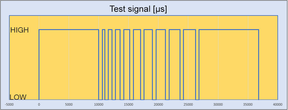
You can mark a signal as a “real” signal by placing it in a clearly identifiable start and end signal (kind of ID) . In my first test signal these are very “HIGH” continuous signals of 10000 µs. In between there are the “HIGH” information signals of 400, 600, 800,….., 2000 µs. These are separated by “LOW” phases of 600 µs.
The sketch looks like this and I don’t think I need any further explanation:
int txPin = 10; /* Transmitter Data Pin */
const int lowLength = 600; /* constant Low Phase */

void setup(){
  pinMode(txPin, OUTPUT);
}

void loop(){
  unsigned int mcs;
  startSequence(); /*Send the startsequence*/
  for(int i=0; i<9; i++){ /* Send nine signals; High: 400, 600, .... */
    digitalWrite(txPin, HIGH);
    mcs = i*200 + 400;
    delayMicroseconds(mcs);
    digitalWrite(txPin,LOW);
    delayMicroseconds(lowLength);
  }
  endSequence(); /* Send the end sequence */
  delay(5000);
}

void startSequence(){
  digitalWrite(txPin, HIGH);
  delayMicroseconds(10000);
  digitalWrite(txPin, LOW);
  delayMicroseconds(lowLength);
}

void endSequence(){
  digitalWrite(txPin, HIGH);
  delayMicroseconds(10000);
  digitalWrite(txPin, LOW);
}
Let’s move on to receiversketch. At first the receiver is waiting for a valid start signal. If this is given, i.e. if a defined length is exceeded, the information signals are analyzed, i.e. the lengths of the “HIGH” and “LOW” phases are measured alternately. These values are stored in a two-dimensional array “signalLength” as “lowCounter” and “highCounter”. The length of the signals is then low- or highCounter x Resolution (here: 20 µs). If “highCounter” exceeds a defined value, it is the end signal. The sequence is thus fully transmitted and will be displayed on the serial monitor.
int resolution = 20;

void setup(){
  Serial.begin(9600);
  DDRD = 0x00; // Arduino Pins D0 - D7 as input
  PORTD = 0x00; // Arduino Pins D0 - D7 set LOW
}

void loop(){
  waitForSignal();
}

void waitForSignal(){
  while(!(PIND & (1<<PD5))){/*Wait for valid signal*/}
  if(startSequence()){ // Is the signal a valid start sequence? */
    analyseSignal(); /* if yes, analyse the signal */
  }
}

void analyseSignal(){
  int signalCounter = 0; /* counter for High/Low signal pairs */
  int lowCounter = 0; /* Low signal length = lowCounter * resolution; */
  int highCounter = 0; /* High signal length = highCounter * resolution; */
  int signalLength[15][2]; /* store the signals in a two-dimensional array */
  bool msgCompleted = false;

  while(!msgCompleted){ /* while the message is not completed */
    lowCounter = 0;
    highCounter = 0;

    while(!(PIND & (1<<PD5))){ /* Wait for HIGH, measure the length of the low signal */
      delayMicroseconds(resolution);
      lowCounter++;
    }
    while(PIND & (1<<PD5)){ /* Wait for LOW, analyse the HIGH signal */
      delayMicroseconds(resolution);
      highCounter++;
    }
    if(highCounter < 200){ /* a Low/High pair has been received */
    signalLength[signalCounter][0] = lowCounter;
    signalLength[signalCounter][1] = highCounter;
    signalCounter++;
  }
  else if(highCounter < 5000){ /* end of message received, the if is redundant */
    msgCompleted = true;
    }
  }
  /* Following is the output */
  Serial.println("low / high");
  for(int i=0; i<signalCounter; i++){
    Serial.print(signalLength[i][0]);
    Serial.print(" / ");
    Serial.println(signalLength[i][1]);
  }
  Serial.println("--------");
  delay(2000);
}

bool startSequence(){
  int counter = 0;
  while(PIND & (1<<PD5)){
    delayMicroseconds(resolution);
    counter++;
  }
  if(counter >400){ /* the start signal has been received */
    return true;
  }
  else{
    return false;
  }
}

And, behold, you get beautiful distinct signals. Since the resolution is 20 µs and the “LOW” signals are 600 µs long, the lowCounter should be 30. Strictly speaking, 29, as he counts starting at zero. So we measure about 100’s too much. And what is too much with the “LOW” signals is missing from the “HIGH” signals. Probably the receiver modules need a certain amount of time to set the data pin to “HIGH” when receiving a signal. In any case, you get a good impression from this at which speeds you can transfer data.
Protocol 1 – bitwise transmission
The basic idea
Now that we have seen that information can be coded by signal length, it is now time to develop our own radio protocols. In the first example, we transfer bits that are defined by the “HIGH” phase length. A “0” is a 600 µs signal and a “1” is a 1200 µs signal. In between there are fixed “LOW” signals of 600 µs. Assuming that zeros and ones occur equally often, the average signal length is 1500 microns, i.e. a transmission rate of “legendary” 0.666 kbit/s. Through the basic experiment above, we have seen that even much shorter signals can still be clearly distinguished. So here’s still a lot of room for increasing the speed.
The transmittersketch
I have defined the information to be transmitted as a string. At first, you can easily break down a string into its individual characters: yourstring [ites Zeichen] . To break down the characters into their 8 bits, I use a binary operation in the “sendeByte” function, which you should understand if you have followed my explanations above. In essencet: the byte is gradually moved to the right. Then the logical “AND” checks whether the first bit is “1” or “0”. Accordingly, a short or long “HIGH” is sent in the sendeSignal() function. I have shortened the end signal to 5000 µs.
int txPin = 10; /* Transmitter Data Pin */

void setup() {
  pinMode(txPin, OUTPUT);
  Serial.begin(9600);
}

void loop() {
  String msgString = "Hallo Welt, wie geht es dir heute?"; // Hello world, how are you today?
  sendeString(msgString);
  delay(5000);
}

void sendeString(String msg) {
  int len = msg.length();
  initMsg(); /* Send the initial signal */
  for (int i = 0; i < len; i++) { /* send bytewise */
    sendeByte(byte(msg[i]));
  }
  closeMsg();
}

void sendeByte(byte msgByte) { /*send bitwise */
  bool msgBit = 0;
  for (int i = 7; i >= 0; i--) { /* "Extraction" of the bits */
    msgBit = (msgByte >> i) & 1;
    sendeSignal(msgBit);
  }
}

void sendeSignal(bool sendBit) {
  digitalWrite(txPin, HIGH);
  if (sendBit == false) {
    delayMicroseconds(600);
  }
  else {
    delayMicroseconds(1200);
  }
  digitalWrite(txPin, LOW);
  delayMicroseconds(1000);
}

void initMsg() { /* Initialise */
  digitalWrite(txPin, HIGH);
  delayMicroseconds(10000);
  digitalWrite(txPin, LOW);
  delayMicroseconds(600);
}

void closeMsg() { /*end signal */
  digitalWrite(txPin, HIGH);
  delayMicroseconds(5000);
  digitalWrite(txPin, LOW);
  delayMicroseconds(600);
}
The receiver sketch
The Receiversketch is very similar to the Receiversketch for the test signal. First, a valid start signal is waited for, then the length of the following signals l are measured and interpreted as bits. The bits are combined into bytes via binary operations, the bytes are converted into characters and the string is reassembled from them. Since only whole bytes can be transferred, there should be no bit left at the end. And if so, then something has gone wrong and an error flag is set.
int resolution = 20;
int error = 0; /* error flag */

void setup(){
  Serial.begin(9600);
  DDRD = 0x00;
  PORTD = 0x00;
  Serial.println("Warte auf Signal...");
}

void loop(){
  listenToSignal();
}


void listenToSignal(){
  int lowPulse = 0;
  int highPulse = 0;
  byte bitNo = 0;
  byte incomingByte = 0;
  String msg = "";
  int msgLen = 0;
  bool msgCompleted = false;
  error=0;

  while(!(PIND & (1<<PD5))){/*Wait*/}
  if(startSequence()){

    while(!msgCompleted){
      lowPulse = 0;
      highPulse = 0;

      while(!(PIND & (1<<PD5))){
        delayMicroseconds(resolution);
        lowPulse++;
      }
      while(PIND & (1<<PD5)){
        delayMicroseconds(resolution);
        highPulse++;
      }
      if(highPulse < 45){
        incomingByte = (incomingByte << 1);
      }
      else if(highPulse < 70){
        incomingByte = (incomingByte << 1) + 1;
      }
      else if(highPulse >= 150){
        msgCompleted = true;
        if(bitNo!=0){
          error = 1;
        }
      }
      if(bitNo<7){
        bitNo++;
      }
      else{
        msg = msg + char(incomingByte);
        bitNo = 0;
        msgLen++;
        incomingByte = 0;
      }
    }
    if((!error)&&(msg.length()!=0)){
      Serial.println(msg);
    }
 //   else{
 //    Serial.println("error");
 //   }
   }
}

bool startSequence(){
  int counter = 0;
  while(PIND & (1<<PD5)){
    delayMicroseconds(resolution);
    counter++;
  }
  if(counter > 300){
    return true;
  }
  else{
    return false;
  }
}
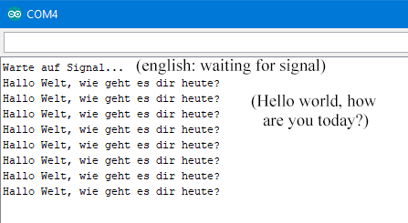
And look – it works!
Protocol 2 – Transfer numbers digitwise
The basic idea
I subsequently edited this chapter again in 2024.
With this protocol, only integers are transmitted. To do this, we divide the number into its digits and encode them by their length. Each signal is given an offset so that we can also transmit zeros.
The transmitter side
We define the number to be transferred as a character array. This makes it easy to cut it into digits. And we don’t have to worry about the maximum size of integer or long integer values.
int dataPin =  5; /* Transmitter data pin */
const int lowLength = 600; /* low phase is constant */
char message[] = "0123456789";

void setup() {
  pinMode(dataPin, OUTPUT);
}

void loop() {
  unsigned int mcs;
  sendStartSequence();
  for (unsigned int i=0; i < sizeof(message)-1; i++) { /* */
    /* Make an integer from the char array element */
    char element[1] = {message[i]};
    int digit = atoi(element);

    mcs = digit * 200 + 250; // mcs: signal length in microseconds
    digitalWrite(dataPin, HIGH);
    delayMicroseconds(mcs);
    digitalWrite(dataPin,LOW);
    delayMicroseconds(lowLength);
  }

  sendEndSequence();  /* Send the terminating sequence */
  delay(5000);
}

void sendStartSequence() {
  digitalWrite(dataPin, HIGH);
  delayMicroseconds(10000);
  digitalWrite(dataPin, LOW);
  delayMicroseconds(lowLength);
}

void sendEndSequence() {
  digitalWrite(dataPin, HIGH);
  delayMicroseconds(10000);
  digitalWrite(dataPin, LOW);
}
The receiver sketch
The receiver first waits for the long start signal. Once it has received this, the incoming signals are evaluated in terms of their length. The sketch saves these values in an array. The digits are reconstructed from the lengths using a conversion factor. You may have to adjust the conversion factor in your case. The example of the transmission 0123456789 should make it easy to see whether the factor is correct.
int resolution = 15;
int dataPin = 5;
#define LEN_TO_NUMBER_DIVIDER 11 /* Divider to calculate numbers from signal length */

void setup() {
  Serial.begin(115200);
  pinMode(dataPin, INPUT);
}

void loop() {
  waitForSignal();
}

void waitForSignal() {
  while (!digitalRead(dataPin)) {/*Wait until data pin receives a signal*/}
  if (startSignalReceived()) {      /* Is the start sequence valid wrt its length? */
    Serial.println("Received valid start signal");
    analyzeIncomingMessage();
  }
}

void analyzeIncomingMessage(){
  int signalCounter = 0; /* Counter for the number of signals */
  int signalLength[15];  /* Signal length array*/
  bool msgCompleted = false;

  while (!msgCompleted){
    signalLength[signalCounter] = 0;

    while (!digitalRead(dataPin)) { /* Wait for high signal */
      delayMicroseconds(resolution);
    }
    while (digitalRead(dataPin)) {   /* Measure the length of the high signal */
      delayMicroseconds(resolution);
      signalLength[signalCounter]++;
    }
    if (signalLength[signalCounter] < 200) {    /* Received message content */
      signalCounter++;
    }
    else { /* Received the termnating signal */
      msgCompleted = true;
    }
  }
  /* Es folgt die Ausgabe */
  Serial.println("Signal length: ");
  for (int i=0; i<signalCounter; i++) {
    Serial.println(signalLength[i]);
  }
  Serial.print("Number received: ");
  for (int i=0; i<signalCounter; i++) {
    Serial.print(signalLength[i]/LEN_TO_NUMBER_DIVIDER);
  }
  Serial.println();
  Serial.println("--------");
  delay(1000);
}

bool startSignalReceived() {
  int counter = 0;
  while (digitalRead(dataPin)) {
    delayMicroseconds(resolution);
    counter++;
  }
  if (counter > 400) { /* Start signal has been received */
    return true;
  }
  else {
    return false;
  }
}
Here is the output, so you see it works:

You can take out the output of the signal lengths.
And then you could develop your own protocols. How about Morse code, for example?