
About the post
In this article I would like to introduce two things: a radio rain warning system in a lunch box and how to build the actual rain sensor yourself. In doing so, I build on the previous posts about 433 MHz radio and radio sockets.
But why a lunch box? Quite simply: Lunch boxes are comparatively rainproof, inexpensive and you can easily open them to change the battery. In other words, a good alternative to the housings that are actually intended for such things. Besides, I just found the idea funny.
Rain sensors
Rain sensors such as those shown here are available for a few euros e.g. from Amazon:

There are two types of rain sensors available: the ones where the detector and the control module are separate components and the compact types. I would always take the former because you can better protect the electronics from moisture. A rain sensor that must not get wet is not really useful.
The sensors are usually supplied with 3-5 V. The model shown at top right right provides a voltage of 0 V between “S” and “-” in dry state. When in contact with water, the voltage goes up and can be detected at an analog input pin. When supplying 5 V, I measured approx. 2.5 V when in contact with a damp finger. The model at top left has a digital output in addition to the analog output. The analog output provides in dry state a high voltage, which decreases when the sensor is in contact with water. The digital output is “HIGH” with dry detector and it is “LOW” with a wet detector. Via the small potentiometer on the module, it is possible to adjust at which analog voltage the digital output changes its status.
How to build such rain sensors yourself is described at the end of this post.
The radio rain sensor project
The receiver side
The rain sensor should warn me if, for example, my laundry is outside for drying and it starts to rain. In my project, it switches a radio socket connected to an alarm siren. You can buy such a siren for about 20 euros in electronics shops. Of course, you can also choose warning mechanisms on the receiver side. With a radio receiver module and an Arduino or other microcontroller, there are no limits.

The transmitter side
On the transmitter side I apply an Arduino Nano, which you can buy for a few euros from Amazon. A simple 433 MHz transmitter module is used as a radio module. I used a jumper cable as a simple antenna. This is not ideal, but I didn’t want to make the device big. It is definitely sufficient to send signals from the garden to the inside of my house. Also, to save space, I used a 3.7 V / 720 mAh battery from drone construction. Since the Arduino Nano requires 5 volts, I used a step-up module. Alternatively, you could take a 9 V block battery and save the step-up converter. It is important to note that different pins of the Arduino Nano must be used depending on the supply voltage. Either you connect a 5 volts supply to the pin “5V” or you take “VIN” for a voltage between 7 and 12 volts. As a small extra, I have installed a control LED that lights up as long as the battery voltage is above 3.3 V.
I soldered the whole thing onto a small circuit board and fixed it with 2.5 mm plastic screws and spacers to the lunch box. The on/off switch and the cable to the detector were led out of the housing via small holes. I sealed the holes with silicon glue. Here’s what the result is:

Actually I wanted to create a circuit diagram with Fritzing, but I was too lazy to create new components for the step-up module and the rain sensor. I used TinyCAD and a bit of Photoshop instead.
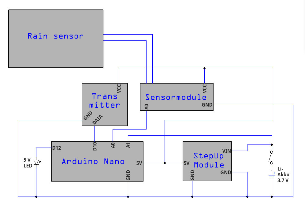
By the way, I have not forgotten the resistor for the LED. It is a 5 V LED. For “normal” LEDs, a 330 Ω resistor should be added.
The sketch
The sketch is likely to be self-explanatory. In the main loop, a rain signal is checked repeatedly. If this happens, the alarm siren is turned on for five seconds and then switched off for another five seconds. In addition, the battery voltage is checked. The RCSwitch library and how to control radio sockets with radio modules is something I have explained in another post.
#include <RCSwitch.h>
RCSwitch mySwitch = RCSwitch();
int analogRainPin = 0;
int analogVoltPin = 1;
int ledPin = 12;

void setup() {
  Serial.begin(9600);
  mySwitch.enableTransmit(10);
  mySwitch.setPulseLength(311);
  pinMode(ledPin, OUTPUT);
}

void loop() {
  if(analogRead(analogVoltPin) > 675) /* Batteriespannung > 3.3 V */
  digitalWrite(ledPin, HIGH);
  else{
    digitalWrite(ledPin, HIGH);
    delay(500);
    digitalWrite(ledPin, LOW);
  }
  if(analogRead(analogRainPin) <= 800){ /* empirischer Grenzwert */
    mySwitch.switchOn("10010", "00100");
    delay(5000);
    mySwitch.switchOff("10010", "00100");
    delay(5000);
  }
  delay(500);
}
What could be done differently (better?)
If I were to build the rain warning system again, I would change two things. On the one hand, I would take an ATtiny (e.g. 85) instead of an Arduino Nano. The performance is sufficient and you could save the step-up converter. Secondly, I would build the detector myself. How to do this I describe in the last part of this post.
How to make the rain sensor yourself
When my project was already finished, I came up with the idea of building the sensor myself – unfortunately a little too late. For this purpose, a rectangular piece is first sawn out of a stripboard. If the detector is to work on both sides, simply place two stripboards on top of each other. Then you connect the first, third, fifth, etc. strip and do the same with the second, fourth, sixth, etc. Both strip groups get a connection. The solder joints for my connections looked quite ugly, so I hided them under some tape.

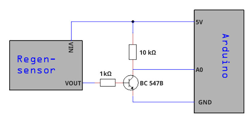
Below you find a circuit diagram for the sensor. I use a 10kΩ resistor and an npn transistor (BC 547B). In dry conditions, no current can flow through the sensor. Accordingly, the npn transistor blocks and the voltage at A0 is 5 V. If the sensor is wet, a small current flows and that opens the transistor, causing the voltage to drop to A0. That’s it.
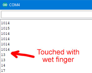
Reading out is easy. In the sketch I take an analog input pin. As you can see below, the signal is not defined enough to work with a digital input.
int analogRainPin = 0;

void setup(){
  Serial.begin(9600);
}

void loop(){
  Serial.println(analogRead(analogRainPin));
  delay(1000);
}
Here’s what it looks like in action:
I hope the radio rain warning system in a lunch box was fun and maybe gave you suggestions for your own projects.