About this Post
Update May 2026: As ATTinyCore is not currently being maintained, I recommend TinyCore as an alternative. TinyCore is based on ATTinyCore. The only thing missing (for now?) is Digispark support. Click here to read my post about TinyCore.
Some time ago, I had written a post about “Programming ATtiny85 / 84 / 45 / 44 /25 / 24“. I had used the board manager package “attiny” by David A. Mellis at that point of time. However, there is another package called ATTinyCore from Spence Konde, which covers many more representatives of the ATtiny family and is considerably more convenient. In addition, both the range of functions and the differences of the individual representatives of the ATtiny family are documented excellently.
So, it’s time for a new post on this topic! What topics I will cover:
- Advantages of ATTinyCore vs. attiny
- The ATtiny Family – Overview
- Preparing the Arduino IDE
- Uploading sketches to the ATtiny
- Uploadind via ISP and using the serial monitor
Advantages of ATTinyCore vs. attiny
ATTinyCore can do everything the older package “attiny” can do, only more. Here are the most important advantages from my point of view:
- You can currently program 20 ATtiny MCUs instead of 6.
- ATTinyCore handles I2C, SPI and UART (Serial) without the need for additional libraries.
- Larger bootloader selection (does not apply to all representatives, though):
- Without, i.e. programming via ISP.
- Optiboot, i.e. “Arduino-like” programming via serial.
- Micronucleus (VUSB), i.e. programming à la Digispark.
- More fine-tuning is possible, like (de)activating micros()/millis() or setting the BOD level (Brown Out Detection).
I would like to emphasize the second point in particular. Most ATtinys have a so-called USI interface (Universal Serial Interface) instead of a “real” I2C, SPI and UART interface. It is possible to implement I2C, SPI and UART using the USI interface, but this requires a corresponding software solution. And exactly this is already implemented in ATTinyCore.
The ATtiny Family – Overview
I counted in Microchip Studio (formerly Atmel Studio), the software from Microchip for programming the AVR and SAM microcontrollers: There you can choose between 75 different ATtiny MCUs. Quite a large family, I would say.
Which ATtinys you can program with ATTinyCore
Here is a list of ATtiny MCUs which are suitable for ATtinyCore:

The table lists only a few technical features of the ATtinys. If you want to know more and don’t feel like reading long datasheets, I can really highly recommend browsing through the ATTinyCore documentation on GitHub.
Not covered ATtiny types in ATtinyCore

There is another package from Spence Konde called megaTinyCore. This covers the ATtiny types listed on the right, which are fundamentally different from the other family members. They are not programmed via ISP, but via UPDI (Universal Programming and Debugging Interface). UPDI is a “single-wire” method, which means it runs over a single data cable.
I will write a separate post about the UPDI-based ATtinys later. First, I still have to familiarize myself with it.
Why should I use ATtiny MCUs?
If you compare the performance of ATtiny MCUs with those of an ESP32, ESP8266 or ATmega types, the ATtinys do not necessarily look good. BUT: They are small, they are power efficient, and they are usually cheap. For many projects, the large MCUs are oversized.
Preparing the Arduino IDE
Update 01/2025: the latest version of the board package is currently 2.0.0. You can only install it manually. On GitHub, you’ll find a note stating that this is a beta version. Moreover, Spence Konde also recommends using his package for the outdated Arduino IDE 1.8.13 (see here). Unfortunately, no further updates have been released since the launch of version 2.0.0. As issues with this version have been reported, I recommend installing version 1.5.2 first. You can now install this (once again) via the Arduino IDE (see below). Only once all of that is working would I try version 2.0.0.
Installation of Version 2.0.0 (I do not recommend)
- Follow this link, click on the green ” Code” button, and then click “Download ZIP”.
- Save the ZIP file in the “hardware” subfolder within your Sketchbook directory (i.e. where your sketches are saved to). If the “hardware” folder doesn’t exist, create it. If you don’t know where your Sketchbook directory is, go to File → Preferences. It’s shown right at the top.
- Extract the ZIP file. If your ZIP program does not create the directory “ATTinyCore-2.0.0-devThis-is-the-head-submit-PRs-against-this” (which may have a different version number) directly under “hardware”, then move it there. I would also recommend renaming the awkward name to “ATTinyCore 2.x.x”.
Installation of Version 1.5.2 (my preference)
In the Arduino IDE, go to File → Preferences. Click the icon next to “Additional Boards Manager URLs”. In the window that pops up, enter the following line:
https://descartes.net/package_drazzy.com_index.json
Then close the windows by clicking “OK”.

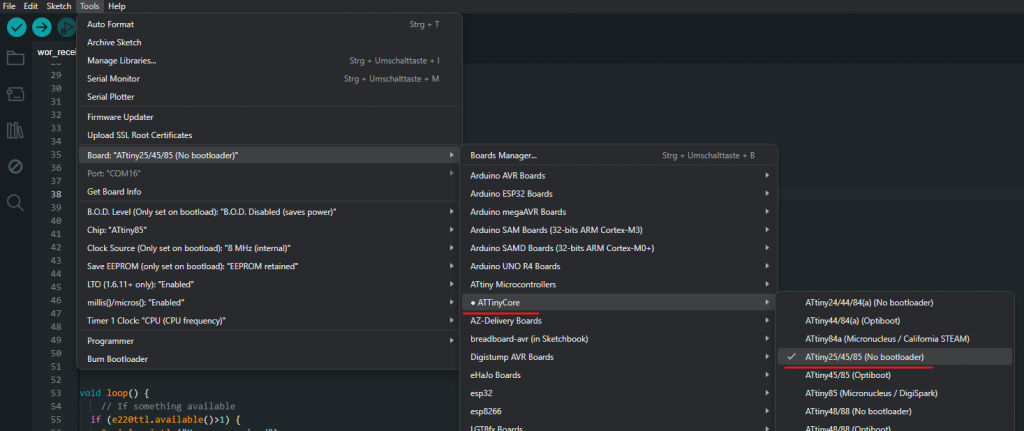
Now navigate to Tools → Board → Boards Manager. Enter “attiny” as a search term and install ATTinyCore from Spence Konde.

If everything works, you should now find ATTinyCore among the selectable board groups:
Uploading sketches to the ATtiny
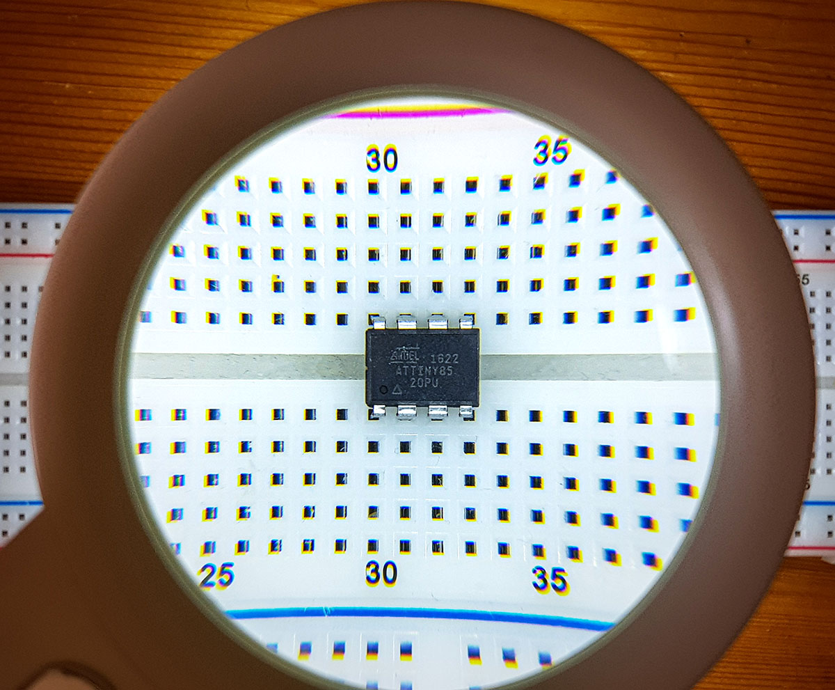
Now comes the more interesting part because now we upload sketches to the ATtiny. There are, as already mentioned, three methods. As a demonstration object, I use the popular ATtiny85. However, I have also successfully tested an ATtiny4313, an ATtiny861 and an ATtiny1634 with the options available in each case.
For better orientation, here is the pinout of the ATtiny85:

The methods presented here can be easily transferred to the other ATtinys.
Option 1: Upload without bootloader (ISP)
The most common, “natural” way to program a microcontroller is ISP (In-System Programming). The designation is intended to make clear that the microcontroller can be programmed in its application environment. Therefore, it does not need to be prepared separately before its installation.
The ISP programming is done via the pins of the SPI interface. Since the pin designations are also the same (MOSI, MISO, SCK), the wiring is simple.
Variant 1: The Arduino as ISP Programmer
Preparation
The bad news is that you need a programmer to program via ISP. The good news is that you can turn an Arduino UNO or Nano into a programmer. You only have to do one thing:
- Upload the ArduinoISP sketch to the board that will serve as the programmer. You can find the sketch in the Arduino IDE under File → Examples → Built-In Examples → ArduinoISP.
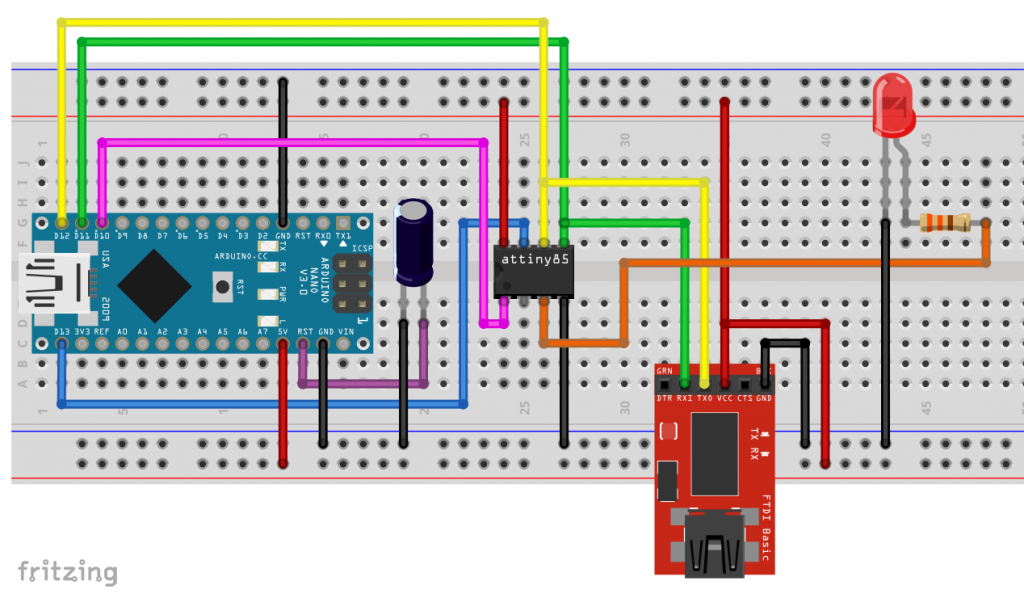
Now connect the programmer you just created to the ATtiny as follows (Arduino Nano as example):
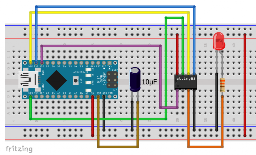
On the Arduino board, MOSI is the digital pin 11, MISO is 12 and SCK is 13. Where the corresponding pins of the microcontroller are located is easy to find out via its pinout scheme. Connect the digital pin 10 of the Arduino to the reset pin of the ATtiny. Connect a capacitor (10 µF) to the reset pin of the Arduino. We will use the LED at PB4 later. You do not need it for programming.
If you have first built the circuit and then want to upload the ArduinoISP sketch, the capacitor can cause problems. Remove it when uploading.
Upload
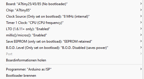
Now select the board family and the microcontroller in the Arduino IDE.
Then you can adjust some settings, such as the clock rate. It is best to leave the other setting options unchanged for now.
Choose “Arduino as ISP” as programmer.
Before the sketch upload, click on “Burn bootloader”. This is misleading because no bootloader is burned, only the so-called fuse bits are set. These are non-volatile, i.e. permanently set bits, with which the settings just described are applied to the microcontroller.
And now you can finally upload a sketch. In the new Arduino IDE (version > 2.0 or later), you need to press Ctrl + Shift + U or go via the menu: Sketch → Upload via Programmer. I usually test first to see if a simple blink sketch like the following works:
int ledPin = 4;

void setup() {
  pinMode(ledPin, OUTPUT);
}

void loop() {
  digitalWrite(ledPin, HIGH);
  delay(500);
  digitalWrite(ledPin, LOW);
  delay(500);
}
Variant 2: Using other ISP programmers
Programmer overview
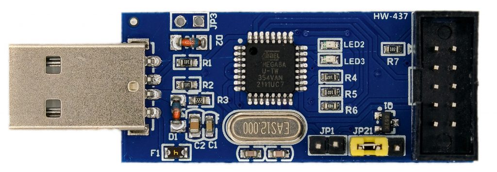
If you are passionate about ATtiny programming, I recommend buying an ISP programmer A cheap option is the USBtinyISP, which you can get for <10 Euro e.g. on Amazon. If a driver is needed, check here at Adafruit.
It is best to invest in an ISP breadboard adapter (right), which will make your life much easier and reduce the risk of incorrect wiring.
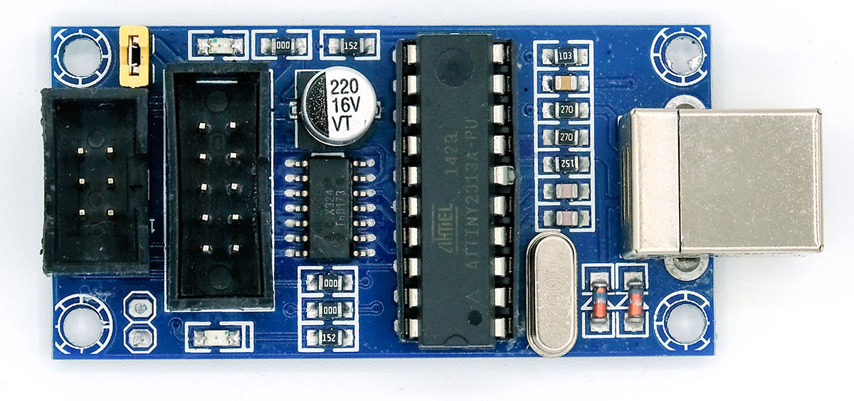
USBasp programmers are similarly priced. For the piece I bought (see below), there was even a good manual available, which is otherwise unfortunately rare.
A slightly more expensive programmer, but one that also works with the Arduino IDE and Microchip Studio, is the Diamex USB-ISP. You can get it here for just over 20 Euros. Alternatively, these pieces are available as Tremex USB ISP Programmer in online shops.
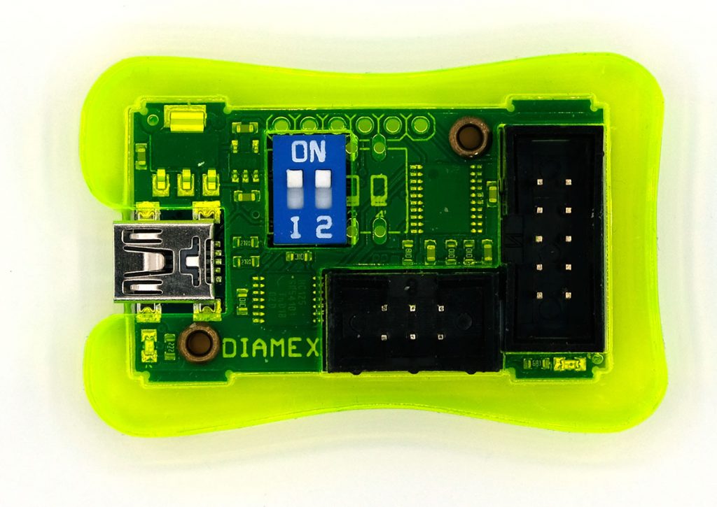
The luxury variant is the ATATMEL-ICE Programmer (ishort: ATMEL-ICE). It works with the Arduino IDE, with Microchip Studio, handles debugWire and UPID. But then you’ll have to pay around 150 Euros…
Connection to the ATtiny and upload

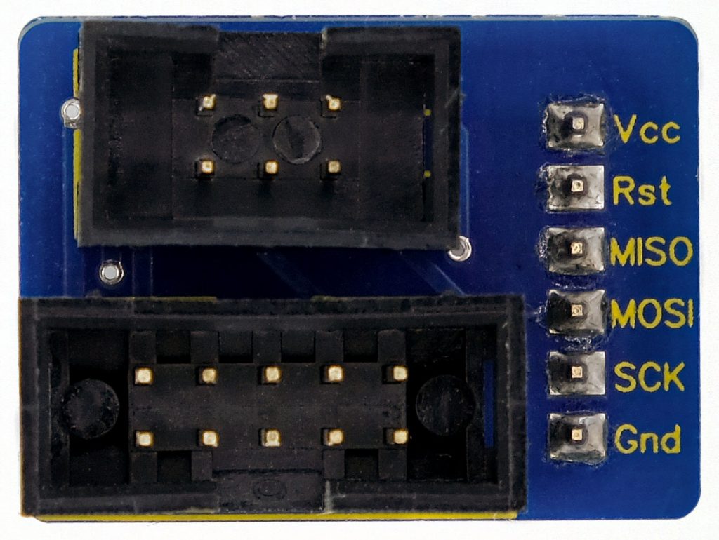
The connection to the ATtiny is self-explanatory using the schematic for the ISP connector shown on the right.
Since it is easy to make a mistake, I repeat myself and recommend the already mentioned adapter for breadboard circuits.
To upload sketches, select the target microcontroller in the Arduino IDE, the programmer and burn the bootloader before the first upload. Then you can upload the first example sketch.
Option 2 – Upload with Optiboot Bootloader
About the Optiboot Bootloader
This method is the one that is also used on the Arduino boards. The Optiboot bootloader ensures that the sketches are uploaded via the serial interface (USI with ATtiny, otherwise UART). The advantage is that fewer lines are needed than when uploading via ISP. Also, you can use the serial monitor as if you were using an Arduino development board. The big drawback is that the bootloader takes up almost 600 bytes of flash memory. Therefore, ATTinyCore does not support the Optiboot bootloader for the ATtinys with 2 KB memory.
Burning the bootloader

Unfortunately, you still have to burn the Optiboot bootloader via ISP. I.e. at least once you have to apply one of the previously described procedures (option 1 or 2). When setting the target microcontroller, select the Optiboot variant.
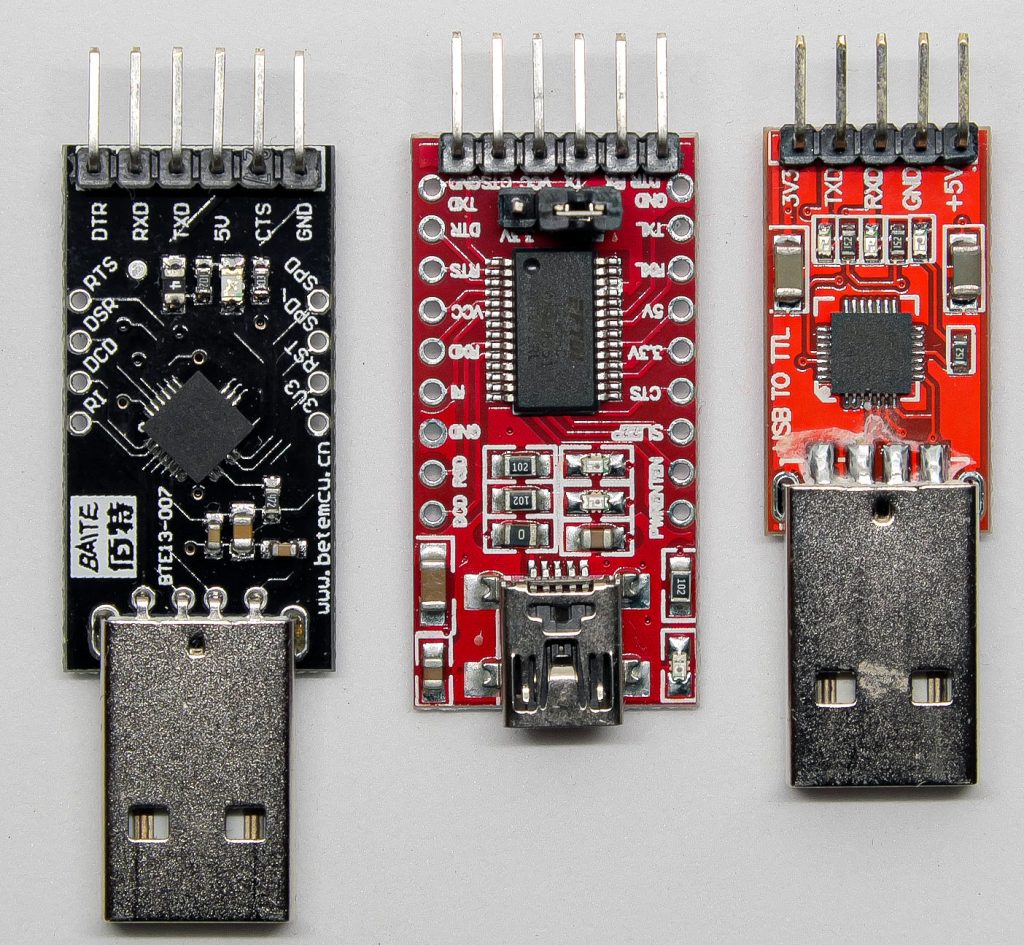
USB to TTL Adapter
To enable the USB interface of your PC to communicate with the serial interface of the ATtiny, you need an adapter. You can find these in online shops for a few Euros under the name “USB-to-TTL”, “USB-UART” or “FT232RL-FTDI” adapter.
Connection to the ATtiny
Connect the RX pin of your adapter to AIN0 of the ATtiny and TX to AIN1. Then connect VCC with VCC and GND with GND. The button at the reset pin of the ATtiny shall only indicate that you can pull it down to LOW if needed. Whilst the sketch is compiling before upload, put the ATtiny into reset mode by connecting it to GND. Then, when you’re ready to upload, the process will pause. The upload will start when you disconnect the Reset-GND connection.

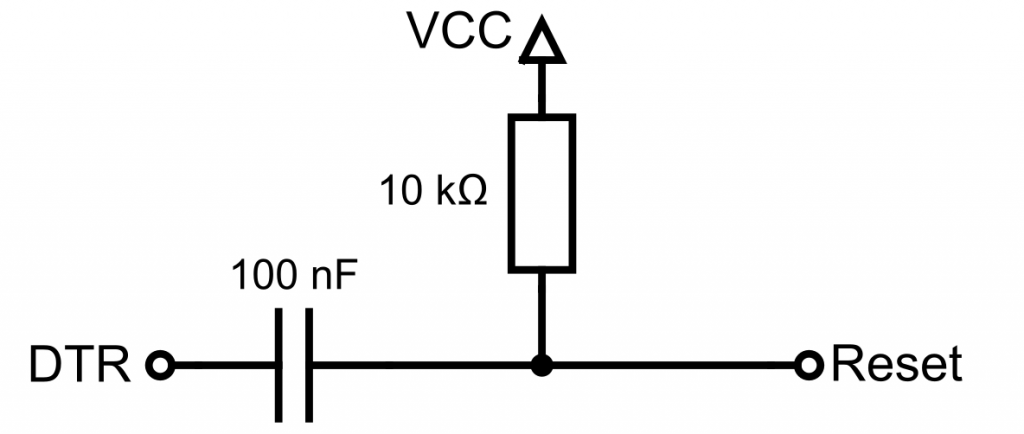
Alternatively to the pushbutton, you can use the adapter’s DTR pin for uploading, if available. This is much more convenient. To do this, you need to connect the adapter’s DTR pin to the ATtiny’s reset pin via a capacitor and add a pull-up resistor:
Please note: close the serial monitor during the upload!
Uploading sketches
Select the port to which the USB-to-TTL adapter is connected. It doesn’t matter which programmer you set. Now upload your sketch. To do this, wait until the sketch is compiled, and the actual upload should begin. Then perform a reset on the ATtiny. This is where the button comes into play (or the DTR pin). I have extended the test sketch a bit to check if the output on the serial monitor works.
const int ledPin = 4;

void setup() {
  Serial.begin(9600);
  pinMode(ledPin, OUTPUT);
}

void loop() {
  Serial.println("Hello World");
  digitalWrite(ledPin, HIGH);
  delay(500);
  digitalWrite(ledPin, LOW);
  delay(500);
}
Option 3 – Micronucleus: we build a Digispark!
About the Micronucleus
The Micronucleus is the bootloader used on the Digispark boards. Thereby the ATtiny is programmed directly via USB without adapter. To make this possible, the Micronucleus uses a technique called VUSB. This means that components that do not have a hardware USB interface can also be addressed via USB.
A certain advantage of the Micronucleus is that you can convert the reset pin of the ATtiny into a GPIO. The disadvantage is – as with the Optiboot – the reduction of the available flash memory. Unfortunately, the memory requirements of the Micronucleus are even greater. From the 8192 bytes of an ATtiny85, you have only 6586 bytes left for your sketches.
Preparation
If you haven’t worked with Digispark yet, you will first need to install a driver for the Micronucleus, which you can download here. Unzip the file and run “Install Drivers.exe” for a 32-bit system or “DPInst64.exe” for a 64-bit system.
Then you have to burn the bootloader once via ISP (“Fresh Install”):
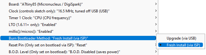
For the reset pin you can choose “Reset” or “GPIO”. With “GPIO” you have one GPIO more available, but you can’t program the ATtiny via ISP anymore. You would first have to perform a bootloader upgrade via USB and give the reset pin back its reset function.
Wiring
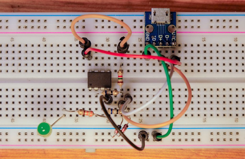
For the circuit you need, besides the ATtiny, two 68 Ω resistors, one 1.5 kΩ resistor and two 3.6 volt Zener diodes. The Zener diodes are used to protect the USB interface of your computer because the data lines use 3.3 volts. So be careful what you do!
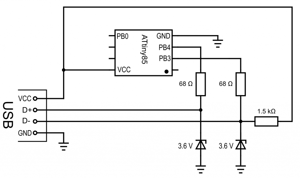
For the USB connection, I recommend a USB break-out module, which you can get for < 1 Euro in online-shops This is how the circuit looked like on the breadboard:
Which pins to connect to the USB lines when using other ATtinys can be found in the ATTinyCore documentation on GitHub. Follow this link and then click on the ATtiny of your choice.
The complete circuit diagram for a Digispark can be found here. It includes the voltage regulator and the on-board LED.
Uploading sketches
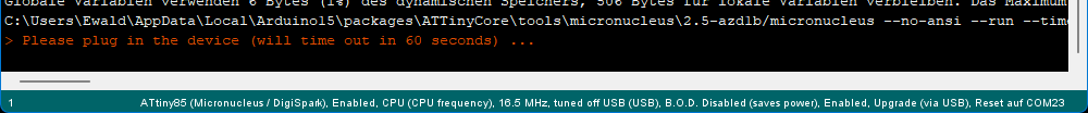
Uploading works like using a digispark. This means that you do not initially connect your circuit to the computer via USB. As programmer, you choose the “Micronucleus” in the Arduino IDE. Then you start the upload. You do not connect to the USB until prompted to do so:
Uploadind via ISP and using the serial monitor
You don’t want a bootloader and still want to use the serial monitor? There are two options.
Option 1: additionally use the USB to TTL Serial Adapter
To upload the sketches, proceed as described above for ISP and also connect the USB-to-TTL adapter. In the circuit below I use the serial pins AIN0 and AIN1 for this purpose. Alternatively, you can also set up a SoftwareSerial connection.
Option 2: with modified ArduinoISP Sketch
I have found a nice alternative here. Some clever person has modified the ArduinoISP sketch so that you don’t need an additional adapter to use the serial monitor. Very smart! I have tried it and it works fine.
Acknowledgement
The ATTinyCore package from Spence Konde is just fantastic! Thank you very much.
How you can support me
Did you enjoy this post and would you like to support me or the site? Then take a look here. By doing so, you can help ensure that this site remains ad-free.