
About this Post
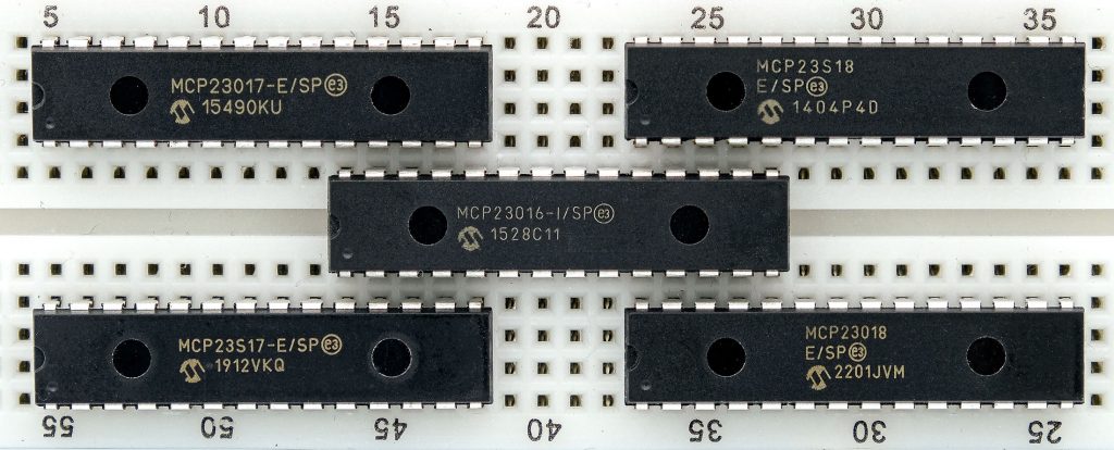
In one of my first posts, I wrote about the MCP23017 port expander and my associated library. I have since adapted the library so that you can also use it for other members of the MCP23x1y family. That is why I am returning to this topic. In this post, I will primarily discuss the differences between the MCP23x1y ICs. For details that are the same for all members of the MCP23x1y port expander family, please refer to my post about the MCP23017.
Incidentally, the somewhat cumbersome designation MCP23x1y is not official. “MCP23x” would also have included the MCP23008 and MCP23S08 models, which I will not discuss in detail here. They only have 8 GPIOs.
These are the topics I will discuss:
- Overview of the MCP23x1y family
- Use of the MCP23x1y port expanders in detail
- I2C vs. SPI – speed tests
Overview of the MCP23x1y family
The MCP23x1y family comprises five members:
- the MCP23016 (link to data sheet)
- MCP23017 / MCP23S17 (link to data sheet)
- and finally the two MCP23018 / MCP23S18 (link to data sheet)
Here is an overview of the most important features of the MCP23x1y port expander:
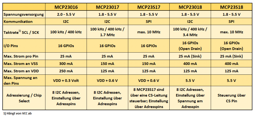
The most common representative is the MCP23017. Like the MCP23018, it is I2C-controlled. If you want to switch or read the GPIOs (General Purpose Input Output) at a higher speed, then use one of the SPI-controlled “S” variants.
The maximum current that can flow through a pin is 25 mA for all members of the MCP23x1y family. However, this current may only flow simultaneously through all pins in the “18” variants. These variants also have a restriction regarding the direction of current flow. The GPIOs of the MCP23018 and MCP23S18 are “open drain” inputs/outputs. This means that they behave like a simple transistor. You can open them (set to OUTPUT) and thus “allow current to flow to ground”, but you cannot use them as a current source.
The MCP23016 is special. It is the only one with a different register structure. It also requires an external clock generator. Since it has been labelled “not recommended for new designs” by the manufacturer Microchip, I have not bothered to adapt my library for it. However, for the sake of completeness, I have included it in the list.
Use of the MCP23x1y port expanders in detail
Below, I will discuss the following points for each member of the MCP23x1y family:
- Pinout
- Connection to the microcontroller
- Simple input/output operations with the MCP23017_WE library
As you can see, I have kept the name of the library. This is because I did not want to confuse those who already use the library.
MCP23017
Pinout
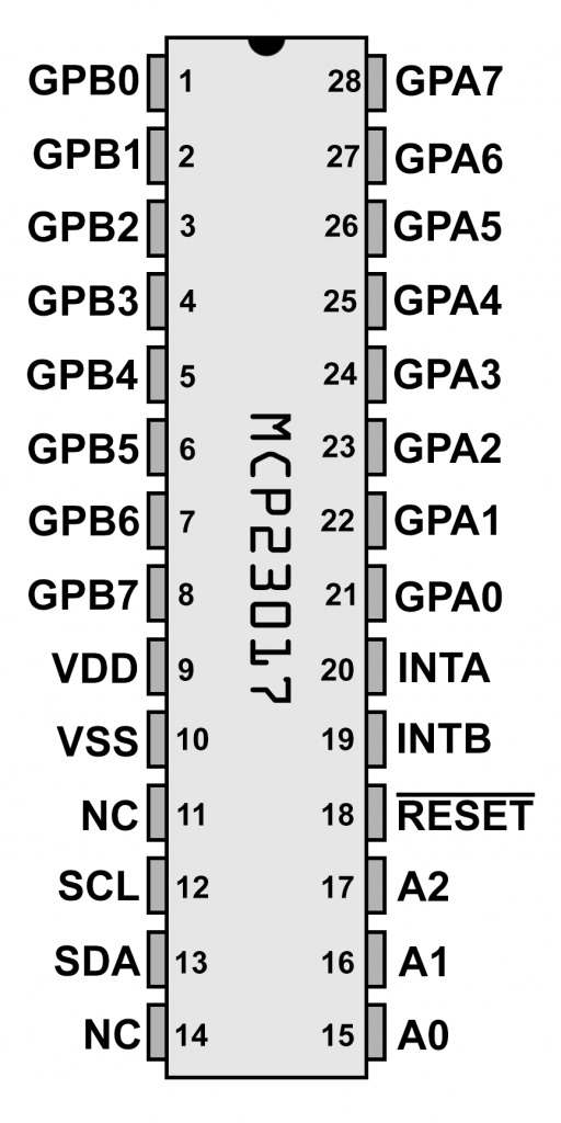
We’ll start with the MCP23017. You supply it with 1.8 to 5.5 volts via VDD/VSS. It is connected to the microcontroller’s I2C pins via SDA and SCL. The I2C connection often works without pull-up resistors, but I would recommend using them. We do not need the interrupt pins for the sketches used in this article. Connect the reset pin to an I/O pin on your microcontroller.
The I2C address is set using the following scheme: 0b00100-A2-A1-A0. If Ax is HIGH, replace it with a 1, otherwise replace it with a zero. So, for example, if you connect A0, A1 and A2 to LOW, the address is 0b00100000 = 0x20 = 32.
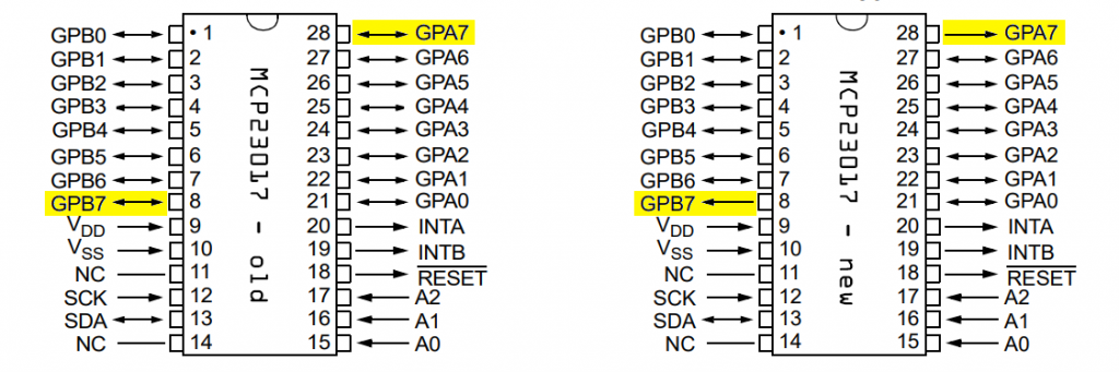
Important notice!!! The data sheet for the MCP23017 changed in 2022. According to the new version, pins GPA7 and GPB7 have lost their input function. The pins are now pure OUTPUT pins. Microchip appears to have responded to reported problems with this change. The problems may or may not occur. You can find a statement from Microchip on this here. Personally, I have not noticed any malfunctions so far.
Example circuit
To try out the sample sketches, connect each GPIO to an LED. When selecting LEDs, keep in mind that the total current at VDD should not exceed 125 milliamps. This means that when all LEDs are lit, each individual LED may only consume an average of approximately 7.8 milliamps. The circuit on an Arduino Nano could look like this:
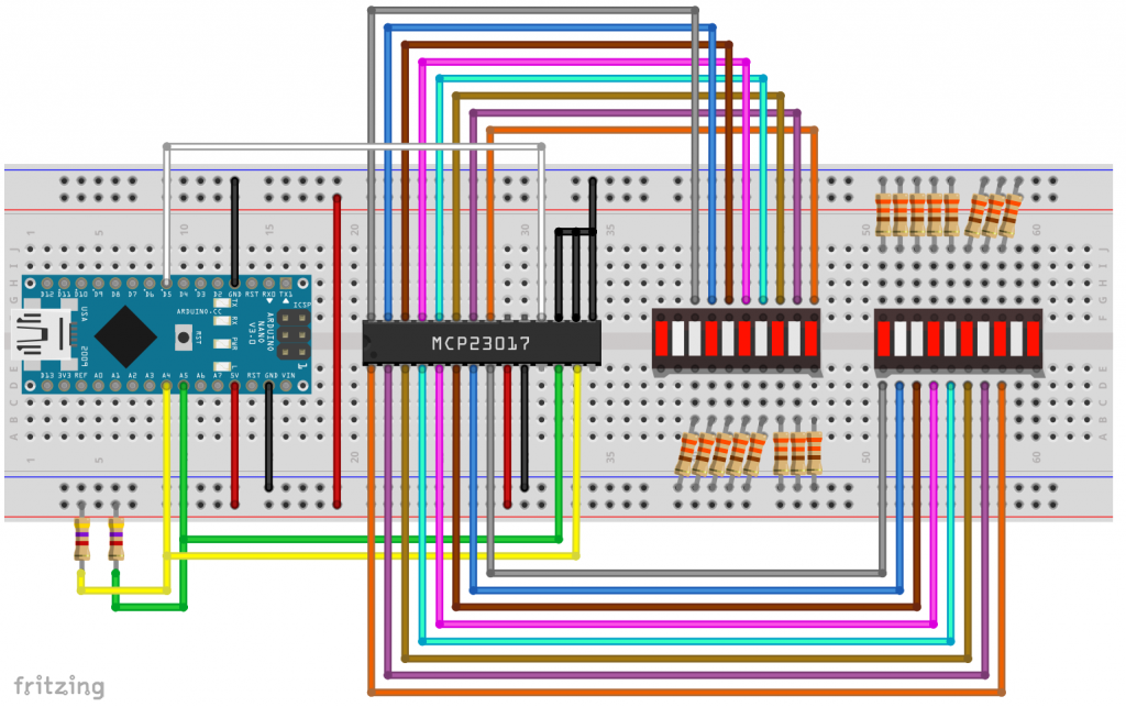
If, like me, you don’t feel like wiring sixteen resistors and LEDs, then I recommend LED bars with integrated resistors, as shown below. They are available with a common anode or cathode:

I found the LED bars on AliExpress, by the way. This makes assembly quick and easy. And they only consume 2 to 3 milliamps per LED. This is what it looked like on my breadboard (without pull-ups):

Example sketch for the MCP23017
The following example sketch shows how to create your MCP23017 object and control the LEDs with various functions.
#include <Wire.h>
#include <MCP23017_WE.h>
#define RESET_PIN 5
#define MCP_ADDRESS 0x20 // (A2/A1/A0 = LOW)

/* There are several ways to create your MCP23017 object:
 * MCP23017_WE myMCP = MCP23017_WE(MCP_ADDRESS)            -> uses Wire / no reset pin (if not needed)
 * MCP23017_WE myMCP = MCP23017_WE(MCP_ADDRESS, RESET_PIN)  -> uses Wire / RESET_PIN
 * MCP23017_WE myMCP = MCP23017_WE(&wire2, MCP_ADDRESS)    -> uses the TwoWire object wire2 / no reset pin
 * MCP23017_WE myMCP = MCP23017_WE(&wire2, MCP_ADDRESS, RESET_PIN) -> all together
 */

typedef MCP23017_WE MCP;
MCP myMCP = MCP(MCP_ADDRESS, RESET_PIN);  // short version
// MCP23017_WE myMCP = MCP23017_WE(MCP_ADDRESS, RESET_PIN);  // long version

int wT = 500; // wT = waiting time

void setup(){
  Wire.begin();
  myMCP.Init();
  delay(wT);
  myMCP.setPortMode(0b11111111, MCP::A);  // Port A: all pins are OUTPUT
  myMCP.setPortMode(0b11111111, MCP::B);  // Port B: all pins are OUTPUT
  myMCP.setAllPins(MCP::A, MCP::ON);      // Port A: all pins are HIGH
  myMCP.setAllPins(MCP::B, MCP::ON);      // Port B: all Pins are HIGH
  delay(wT);
  myMCP.setAllPins(MCP::A, MCP::OFF);     // Port A: all pins are LOW
  myMCP.setAllPins(MCP::B, MCP::OFF);     // Port B: all pins are LOW
  delay(wT);
  byte portValue = 0;
  for(int i=0; i<8; i++){
    portValue += (1<<i); // 0b00000001, 0b00000011, 0b00000111, etc.
    myMCP.setPort(portValue, MCP::A);
    delay(wT);
  }
  portValue = 0;
  for(int i=0; i<8; i++){
    portValue += (1<<i); // 0b00000001, 0b00000011, 0b00000111, etc.
    myMCP.setPort(portValue, MCP::B);
    delay(wT);
  }
  myMCP.setAllPins(MCP::A, MCP::OFF);     // Port A: all pins are LOW
  myMCP.setAllPins(MCP::B, MCP::OFF);     // Port B: all pins are LOW
  delay(wT);
  myMCP.setPin(3, MCP::A, HIGH);          // Pin 3 / PORT A is HIGH
  myMCP.setPin(1, MCP::B, HIGH);          // Pin 1 / PORT B is HIGH
  delay(wT);
  myMCP.setAllPins(MCP::A, MCP::OFF);     // Port A: all pins are LOW
  myMCP.setAllPins(MCP::B, MCP::OFF);     // Port B: all pins are LOW
  myMCP.setPortMode(0, MCP::A);           // Port A: all pins are INPUT
  myMCP.setPortMode(0, MCP::B);           // Port B: all pins are INPUT
  myMCP.setPinX(1, MCP::A, OUTPUT, HIGH); // A1 HIGH
  delay(wT);
  myMCP.togglePin(1, MCP::A);             // A1 LOW
  delay(wT);
  myMCP.togglePin(1, MCP::A);             // A1 HIGH
  delay(wT);
  // the following two lines are similar to setPinX(2,MCP::B,OUTPUT,HIGH);
  myMCP.setPinMode(2, MCP::B, OUTPUT);    // B2 is OUTPUT
  myMCP.setPin(2, MCP::B, HIGH);          // B2 is HIGH
  delay(wT);
  myMCP.setPortX(0b00001111, 0b10001111, MCP::B); // B0-B4: OUTPUT/HIGH, B7: INPUT, HIGH;
}

void loop(){
}
This post is not intended to be a repeat of my first post about the MCP23017, but a few explanations are certainly in order so that you don’t have to jump back and forth between posts.
The GPIOs of the MCP23017 work in principle like those of an Arduino or other microcontrollers. You can set them as INPUT or OUTPUT, and you can switch them to HIGH or LOW. If you supply power to the LEDs via the GPIOs, the pins must be OUTPUT/HIGH for the LEDs to light up.
I have added a number of functions to the library that allow you to address individual pins or entire ports. “0” is always INPUT or LOW. “1” is OUTPUT or HIGH. Instead of HIGH or LOW, you can also use “ON” or “OFF”. These are all just synonyms for 0 or 1.
setPinMode(): determines the mode (INPUT / OUTPUT) for a pin.setPortMode(): sets INPUT/OUTPUT for an entire port, but individually for each pin.setPin(): sets a pin to HIGH or LOW.setPort()HIGH/LOW for an entire port, but individually for each pin.setAllPins(): sets all pins of a port uniformly to HIGH or LOW.setPinX(): combinessetPinMode()andsetPin()in one function.setPortX(): combinessetPortMode()andsetPort()in one function.togglePin(): switches a pin from HIGH to LOW or vice versa.
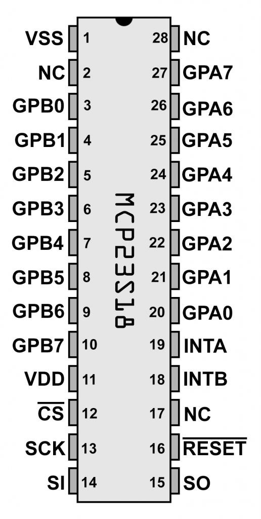
MCP23S17
Pinout
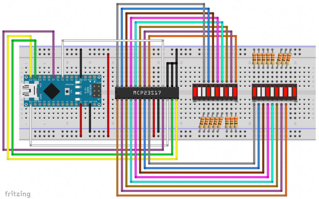
Unlike the MCP23017, the MCP23S17 is controlled via SPI. Accordingly, it has an SCK (serial clock), SI (slave in), SO (slave out) and a CS (chip select) pin.
At first, it is surprising that it also has the three address pins A0, A1 and A2. When you address the MCP23S17 via SPI, you must first pull the CS pin to LOW as usual. Then you send a control byte consisting of the address and the read/write bit. This has the advantage that you can connect eight MCP23S17 ICs to one and the same CS line. This is followed by the register byte and then the data. Of course, you don’t have to worry about these things in detail, as the library takes care of them.
Example circuit
The circuit for control via Arduino Nano is not particularly surprising:
Example sketch
Since the MCP23S17 differs from the MCP23017 only in terms of SPI communication, the sample sketch is also only slightly different. One function has been added, namely setSPIClockSpeed(). This allows you to select the SPI clock rate within the capabilities of your microcontroller and the MCP23S17 (max. 10 MHz). The default setting for the library is 8 MHz. Otherwise, the sketch requires no further explanation.
#include <SPI.h>
#include <MCP23S17_WE.h>
#define CS_PIN 7   // Chip Select Pin
#define RESET_PIN 5
#define MCP_ADDRESS 0x20 // (A2/A1/A0 = LOW)

/* There are two ways to create your MCP23S17 object:
 * MCP23S17_WE myMCP = MCP23S17_WE(CS_PIN, RESET_PIN, MCP_ADDRESS);
 * MCP23S17_WE myMCP = MCP23S17_WE(&SPI, CS_PIN, RESET_PIN, MCP_ADDRESS);
 * The second option allows you to create your own SPI objects,
 * e.g. in order to use two SPI interfaces on the ESP32.
 */
typedef MCP23S17_WE MCP;
MCP myMCP = MCP(CS_PIN, RESET_PIN, MCP_ADDRESS);
//MCP23S17_WE myMCP = MCP23S17_WE(CS_PIN, RESET_PIN, MCP_ADDRESS);

int wT = 500; // wT = waiting time

void setup(){
  SPI.begin();
  myMCP.Init();
  // myMCP.setSPIClockSpeed(8000000); // Choose SPI clock speed (after Init()!)
  delay(wT);
  myMCP.setPortMode(0b11111111, MCP::A);  // Port A: all pins are OUTPUT
  myMCP.setPortMode(0b11111111, MCP::B);  // Port B: all pins are OUTPUT
  myMCP.setAllPins(MCP::A, MCP::ON);      // Port A: all pins are HIGH
  myMCP.setAllPins(MCP::B, MCP::ON);      // Port B: all Pins are HIGH
  delay(wT);
  myMCP.setAllPins(MCP::A, MCP::OFF);     // Port A: all pins are LOW
  myMCP.setAllPins(MCP::B, MCP::OFF);     // Port B: all pins are LOW
  delay(wT);
  byte portValue = 0;
  for(int i=0; i<8; i++){
    portValue += (1<<i); // 0b00000001, 0b00000011, 0b00000111, etc.
    myMCP.setPort(portValue, MCP::A);
    delay(wT);
  }
  portValue = 0;
  for(int i=0; i<8; i++){
    portValue += (1<<i); // 0b00000001, 0b00000011, 0b00000111, etc.
    myMCP.setPort(portValue, MCP::B);
    delay(wT);
  }
  myMCP.setAllPins(MCP::A, MCP::OFF);     // Port A: all pins are LOW
  myMCP.setAllPins(MCP::B, MCP::OFF);     // Port B: all pins are LOW
  delay(wT);
  myMCP.setPin(3, MCP::A, HIGH);          // Pin 3 / PORT A is HIGH
  myMCP.setPin(1, MCP::B, HIGH);          // Pin 1 / PORT B is HIGH
  delay(wT);
  myMCP.setAllPins(MCP::A, MCP::OFF);     // Port A: all pins are LOW
  myMCP.setAllPins(MCP::B, MCP::OFF);     // Port B: all pins are LOW
  myMCP.setPortMode(0, MCP::A);           // Port A: all pins are INPUT
  myMCP.setPortMode(0, MCP::B);           // Port B: all pins are INPUT
  myMCP.setPinX(1, MCP::A, OUTPUT, HIGH); // A1 HIGH
  delay(wT);
  myMCP.togglePin(1, MCP::A);             // A1 LOW
  delay(wT);
  myMCP.togglePin(1, MCP::A);             // A1 HIGH
  delay(wT);
  // the following two lines are similar to setPinX(2,B,OUTPUT,HIGH);
  myMCP.setPinMode(2, MCP::B, OUTPUT);    // B2 is OUTPUT
  myMCP.setPin(2, MCP::B, HIGH);          // B2 is HIGH
  delay(wT);
  myMCP.setPortX(0b00001111, 0b10001111, MCP::B); // B0-B4: OUTPUT/HIGH, B7: INPUT, HIGH;
}

void loop(){
}
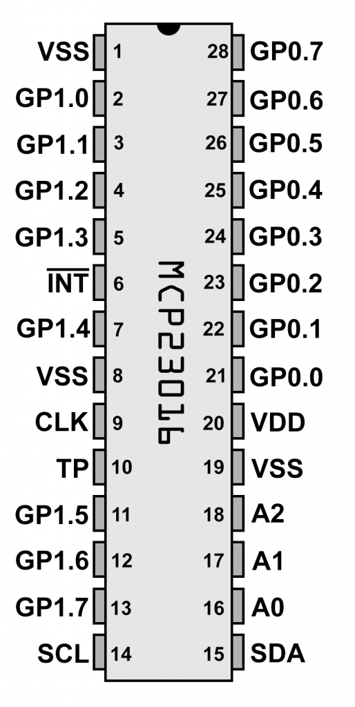
MCP23018
The MCP23018 is also I2C-controlled. However, there is a fundamental difference to the MCP23017. To light up an LED on the MCP23018, you have to use it as a current sink. This means that you do not supply the LED with current via the MCP23018, but rather allow the current to flow through the MCP23018. For this to happen, the respective pin must be in the OUTPUT/LOW state.
Pinout

However, the MCP23018 has another special feature. In addition to the different assignment of the GPIOs, it has only a single address pin. The address is set via the voltage applied to the address pin. This is a rather unusual concept, the advantage of which I do not really understand.
The scale for the “address voltage” is determined by the supply voltage VDD. If you apply 1/16th of the supply voltage to the address pin, the address is 0x20. At 3/16th, it is 0x21, at 5/16th it is 0x22, at 7/16th it is 0x23, etc. You set the highest address 0x27 by applying a voltage of 15/16th VDD. You can also set 0x20 by going to VSS level (0/16th) on the address pin and 0x27 by going to VDD level. The tolerances are lower for the other addresses. An overview of the tolerances and sample tables can be found in the data sheet on page 11.
If you want to operate eight MCP23018 ICs, a circuit (reduced to the I2C part) could look like this:
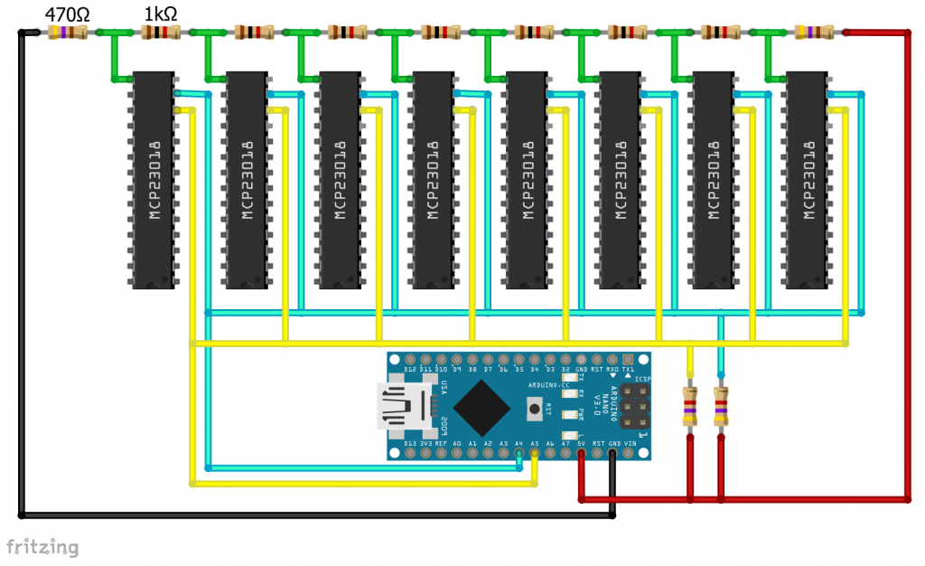
Example circuit
In my example circuit, the LEDs are powered via the Arduino Nano’s 5 volt output. The current flows through the MCP23018. I set the address using a voltage divider. Since I am only using a single MCP23018 here, I could have alternatively connected the address pin to GND or VDD.
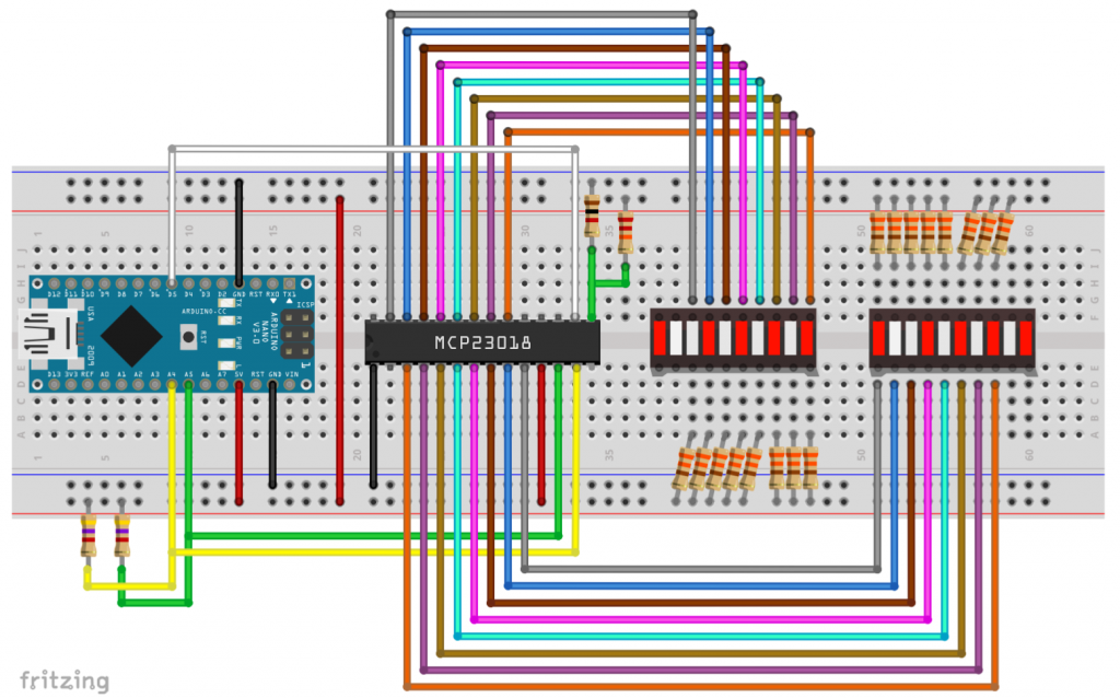
As before, I made life easy for myself and used LED bars with integrated resistors. In this case, of course, the version with a common anode:
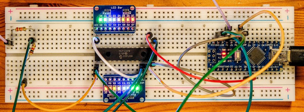
I have also omitted the pull-ups for the I2C lines here (in case you are wondering where they are). However, I added them in the subsequent speed tests.
Example sketch
At first glance, the sketch does not look very different from the previous ones. But if you take a closer look, you will see that I control the LEDs via OUTPUT/INPUT and not via HIGH/LOW.
#include <Wire.h>
#include <MCP23018_WE.h>
#define RESET_PIN 5
#define MCP_ADDRESS 0x20

/* There are several ways to create your MCP23018 object:
 * MCP23018_WE myMCP = MCP23018_WE(MCP_ADDRESS)            -> uses Wire / no reset pin (if not needed)
 * MCP23018_WE myMCP = MCP23018_WE(MCP_ADDRESS, RESET_PIN)  -> uses Wire / RESET_PIN
 * MCP23018_WE myMCP = MCP23018_WE(&wire2, MCP_ADDRESS)    -> uses the TwoWire object wire2 / no reset pin
 * MCP23018_WE myMCP = MCP23018_WE(&wire2, MCP_ADDRESS, RESET_PIN) -> all together
 * Successfully tested with two I2C busses on an ESP32
 */
typedef MCP23018_WE MCP;
MCP myMCP = MCP(MCP_ADDRESS, RESET_PIN); // short version
// MCP23018_WE myMCP = MCP23018_WE(MCP_ADDRESS, RESET_PIN); // long version

int wT = 500; // wT = waiting time

void setup(){
  Wire.begin();
  myMCP.Init();
  delay(wT);
  myMCP.setAllPins(MCP::A, MCP::OFF);     // Port A: all pins are LOW
  myMCP.setAllPins(MCP::B, MCP::OFF);     // Port B: all Pins are LOW
  myMCP.setPortMode(0b11111111, MCP::A);  // Port A: all pins are OUTPUT = LEDs are on!
  myMCP.setPortMode(0b11111111, MCP::B);  // Port B: all pins are OUTPUT
  delay(wT);
  myMCP.setPortMode(0b00000000, MCP::A);  // Port A: all pins are INPUT = LEDs are off
  myMCP.setPortMode(0b00000000, MCP::B);  // Port B: all pins are INPUT
  delay(wT);
  byte portModeValue = 0; // = 0b00000000
  for(int i=0; i<8; i++){
    portModeValue += (1<<i); // 0b00000001, 0b00000011, 0b00000111, etc.
    myMCP.setPortMode(portModeValue, MCP::A);
    delay(wT);
  }
  portModeValue = 0;
  for(int i=0; i<8; i++){
    portModeValue += (1<<i); // 0b00000001, 0b00000011, 0b00000111, etc.
    myMCP.setPortMode(portModeValue, MCP::B);
    delay(wT);
  }
  myMCP.setPortMode(0, MCP::A);          // Port A: all pins are INPUT
  myMCP.setPortMode(0, MCP::B);          // Port B: all pins are INPUT
  delay(wT);
  myMCP.setPinMode(3, MCP::A, OUTPUT);   // Pin 3 / PORT A is OUTPUT/LOW
  myMCP.setPinMode(1, MCP::B, OUTPUT);   // Pin 1 / PORT B is OUTPUT/LOW
  delay(wT);
  myMCP.setPortMode(0, MCP::A);          // Port A: all pins are INPUT
  myMCP.setPortMode(0, MCP::B);          // Port B: all pins are INPUT
  myMCP.setPinX(1, MCP::A, OUTPUT, LOW); // A1 HIGH
  delay(wT);
  myMCP.togglePin(1, MCP::A);             // A1 LOW
  delay(wT);
  myMCP.togglePin(1, MCP::A);             // A1 HIGH
  delay(wT);
  // the following two lines are similar to setPinX(2,B,OUTPUT,LOW);
  myMCP.setPinMode(2, MCP::B, OUTPUT);    // B2 is OUTPUT/LOW
  myMCP.setPin(2, MCP::B, LOW);           // B2 is still OUTPUT/LOW
  delay(wT);
  myMCP.setPortX(0b10001111, 0b10000000, MCP::B); // B0-B4: OUTPUT/LOW, B7: OUTPUT, HIGH;
}

void loop(){
}
If a pin is in the OUPUT/LOW state, the connected LED lights up. Instead of switching it off by changing to INPUT/LOW, you can achieve the same result by switching to OUTPUT/HIGH.
MCP23S18
Pinout
The MCP23S18 offers no big surprises. It is simply the SPI version of the MCP23018. Unlike the MCP23S17, however, it does not have the option of being addressed with different addresses. Accordingly, you must connect each individual MCP23S18 to its own CS line.
Nevertheless, the MCP23S18 expects a “device opcode” consisting of 0x20 and the read/write bit as the first byte for write or read operations. The library takes care of this. However, when creating the MCP23S18 object, you must always pass 0x20 (MCP_SPI_CTRL_BYTE) as well. This is simply for compatibility reasons.
Example circuit
For the sake of completeness, here is the example circuit:

Example sketch
The example sketch is not surprising.
#include <SPI.h>
#include <MCP23S18_WE.h>
#define CS_PIN 7   // Chip Select Pin
#define RESET_PIN 5
#define MCP_SPI_CTRL_BYTE 0x20 // Do not change

/* There are two ways to create your MCP23S18 object:
 * MCP23S18_WE myMCP = MCP23S18_WE(CS_PIN, RESET_PIN, MCP_CTRL_BYTE);
 * MCP23S18_WE myMCP = MCP23S18_WE(&SPI, CS_PIN, RESET_PIN, MCP_CTRL_BYTE);
 * The second option allows you to create your own SPI objects,
 * e.g. in order to use two SPI interfaces on the ESP32.
 */
typedef MCP23S18_WE MCP;
MCP myMCP = MCP(CS_PIN, RESET_PIN, MCP_SPI_CTRL_BYTE); // short version
// MCP23S18_WE myMCP = MCP23S18_WE(CS_PIN, RESET_PIN, MCP_SPI_CTRL_BYTE); // long version

int wT = 500; // wT = waiting time

void setup(){
  SPI.begin();
  myMCP.Init();
  // myMCP.setSPIClockSpeed(8000000); // Choose SPI clock speed (after Init()!)
  delay(wT);
  myMCP.setAllPins(MCP::A, MCP::OFF);    // Port A: all pins are LOW
  myMCP.setAllPins(MCP::B, MCP::OFF);    // Port B: all Pins are LOW
  myMCP.setPortMode(0b11111111, MCP::A); // Port A: all pins are OUTPUT = LEDs are on!
  myMCP.setPortMode(0b11111111, MCP::B); // Port B: all pins are OUTPUT
  delay(wT);
  myMCP.setPortMode(0b00000000, MCP::A); // Port A: all pins are INPUT = LEDs are off
  myMCP.setPortMode(0b00000000, MCP::B); // Port B: all pins are INPUT
  delay(wT);
  byte portModeValue = 0; // = 0b00000000
  for(int i=0; i<8; i++){
    portModeValue += (1<<i); // 0b00000001, 0b00000011, 0b00000111, etc.
    myMCP.setPortMode(portModeValue, MCP::A);
    delay(wT);
  }
  portModeValue = 0;
  for(int i=0; i<8; i++){
    portModeValue += (1<<i); // 0b00000001, 0b00000011, 0b00000111, etc.
    myMCP.setPortMode(portModeValue, MCP::B);
    delay(wT);
  }
  myMCP.setPortMode(0, MCP::A);          // Port A: all pins are INPUT
  myMCP.setPortMode(0, MCP::B);          // Port B: all pins are INPUT
  delay(wT);
  myMCP.setPinMode(3, MCP::A, OUTPUT);   // Pin 3 / PORT A is OUTPUT/LOW
  myMCP.setPinMode(1, MCP::B, OUTPUT);   // Pin 1 / PORT B is OUTPUT/LOW
  delay(wT);
  myMCP.setPortMode(0, MCP::A);          // Port A: all pins are INPUT
  myMCP.setPortMode(0, MCP::B);          // Port B: all pins are INPUT
  myMCP.setPinX(1, MCP::A, OUTPUT, LOW); // A1 HIGH
  delay(wT);
  myMCP.togglePin(1, MCP::A);            // A1 LOW
  delay(wT);  myMCP.togglePin(1, MCP::A);// A1 HIGH
  delay(wT);
  // the following two lines are similar to setPinX(2,MCP::B,OUTPUT,LOW);
  myMCP.setPinMode(2, MCP::B, OUTPUT);     // B2 is OUTPUT/LOW
  myMCP.setPin(2, MCP::B, LOW);            // B2 is still OUTPUT/LOW
  delay(wT);
  myMCP.setPortX(0b10001111, 0b10000000, MCP::B); // B0-B4: OUTPUT/LOW, B7: OUTPUT, HIGH;
}

void loop(){
}
MCP23016
Pinout
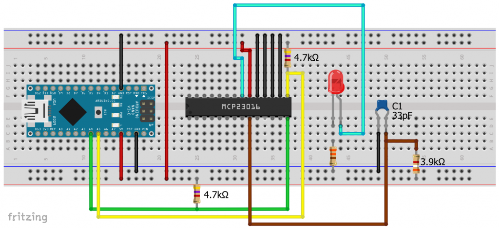
As you can see on the right, the MCP23016 stands out from the other members of the MCP23x1y family. The GPIOs are named differently, and there is no reset pin. There is also a CLK and TP pin.
CLK must be connected to GND via a capacitor and to VDD via a resistor. This is used to set the clock speed. The data sheet recommends a combination of 33 pF / 3.9 kΩ. I also had success with 30 pF / 3.9 kΩ. You can check the clock signal at TP, otherwise leave it unconnected.
The biggest difference to the other family members is its different register architecture. Since it is no longer recommended, I decided not to implement it in my library. Instead, I tried out the CyMCP23016 library, which you can find here on GitHub. Overall, the selection of libraries for the MCP23016 is not huge.
Example circuit with an Arduino Nano
The CyMCP23016 library comes with a sample sketch, which I tested with the following circuit. In the sketch, only one LED is connected to GPIO 0.0. However, this is sufficient to illustrate the principle. I will not display the sketch here.
I2C vs. SPI – speed tests
When I personally have the choice between I2C and SPI, I tend to favour I2C because fewer wires are required. This is especially true when multiple devices need to be controlled. However, SPI has the edge in applications that require high transmission speeds. I conducted a few tests to investigate this.
I2C using the Arduino Nano
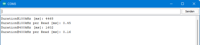
The MCP23017 supports an I2C clock speed of 1.7 MHz, while the MCP23018 supports up to 3.4 MHz. The problem, however, is that most microcontrollers do not support these high clock speeds, including ATmega328P-based Arduinos such as the UNO, Nano or Pro Mini. I tested 100 kHz (standard) and 400 kHz (Fast I2C) on the Arduino Nano. To do this, I determined the time it takes to read a port 10,000 times (digitalRead() for an entire port, so to speak).
Here is the sketch:
#include <Wire.h>
#include <MCP23017_WE.h>
#define MCP_ADDRESS 0x20 // (A2/A1/A0 = LOW)
#define RESET_PIN 5

typedef MCP23017_WE MCP;
MCP myMCP = MCP(MCP_ADDRESS, RESET_PIN);

void setup(){
  Serial.begin(115200);
  long startTime = 0;
  long readTime = 0;
  byte portStatus = 0;
  Wire.begin();
  myMCP.Init();
  startTime = millis();
  for(long i=0; i<10000; i++){
    portStatus = myMCP.getPort(MCP::A);
  }
  readTime = millis() - startTime;
  Serial.print("Duration@100kHz [ms]: ");
  Serial.println(readTime);
  Serial.print("Duration@100kHz per Read [ms]: ");
  Serial.println(readTime/10000.0);

  Wire.setClock(400000);
  startTime = millis();
  for(long i=0; i<10000; i++){
    portStatus = myMCP.getPort(MCP::A);
  }
  readTime = millis() - startTime;
  Serial.print("Duration@400kHz [ms]: ");
  Serial.println(readTime);
  Serial.print("Duration@400kHz per Read [ms]: ");
  Serial.println(readTime/10000.0);
}

void loop(){
}
And here’s the result:
I2C using the ESP32
Dann habe ich den Test mit dem ESP32 wiederholt und dabei versucht, 1.7 MHz einzustellen, da ich meinte, der ESP32 könne das.
#include <Wire.h>
#include <MCP23017_WE.h>
#define MCP_ADDRESS 0x20 // (A2/A1/A0 = LOW)
#define RESET_PIN 18

typedef MCP23017_WE MCP;
MCP myMCP = MCP(MCP_ADDRESS, RESET_PIN);

void setup(){
  Serial.begin(115200);
  long startTime = 0;
  long readTime = 0;
  byte portStatus = 0;
  Wire.begin();
  myMCP.Init();

  startTime = millis();
  for(long i=0; i<10000; i++){
    portStatus = myMCP.getPort(MCP::A);
  }
  readTime = millis() - startTime;
  Serial.print("Duration@100kHz [ms]: ");
  Serial.println(readTime);
  Serial.print("Duration@100kHz per Read [ms]: ");
  Serial.println(readTime/10000.0);

  Wire.setClock(400000);
  startTime = millis();
  for(long i=0; i<10000; i++){
    portStatus = myMCP.getPort(MCP::A);
  }
  readTime = millis() - startTime;
  Serial.print("Duration@400kHz [ms]: ");
  Serial.println(readTime);
  Serial.print("Duration@400kHz per Read [ms]: ");
  Serial.println(readTime/10000.0);

  Wire.setClock(1700000);
  startTime = millis();
  for(long i=0; i<10000; i++){
    portStatus = myMCP.getPort(MCP::A);
  }
  readTime = millis() - startTime;
  Serial.print("Duration@1.7MHz [ms]: ");
  Serial.println(readTime);
  Serial.print("Duration@1.7MHz per Read [ms]: ");
  Serial.println(readTime/10000.0);
}

void loop(){
}
Der magere Geschwindigkeitszuwachs bei 1.7 MHz wunderte mich zunächst:

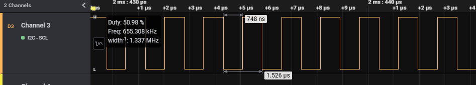
However, measuring the actual clock rate with the logic analyzer revealed that even the ESP32 cannot deliver the 1.7 MHz clock rate. It stopped at 655 kHz. This (roughly) corresponds to what I have found elsewhere on the subject, e.g. here on GitHub.
SPI using Arduino Nano
The Arduino Nano and all other boards based on the ATmega328P can deliver an SPI clock rate of up to 16 MHz. The MCP23S17 can handle an SPI clock rate of 10 MHz. However, you cannot set 10 MHz on the Arduino Nano, only quotients of 16 MHz and integer divisors, i.e. 8 MHz, 4 MHz, 2 MHz, etc. 8 MHz is therefore the maximum. If you specify other values, the next possible lower frequency will be used.
This is the sketch:
#include <SPI.h>
#include <MCP23S17_WE.h>
#define CS_PIN 7   // Chip Select Pin
#define RESET_PIN 5
#define MCP_ADDRESS 0x20 // (A2/A1/A0 = LOW)

typedef MCP23S17_WE MCP;
MCP myMCP = MCP(CS_PIN, RESET_PIN, MCP_ADDRESS);

void setup(){
  Serial.begin(115200);
  long startTime = 0;
  long readTime = 0;
  byte portStatus;
  SPI.begin();
  myMCP.Init();

  myMCP.setSPIClockSpeed(2000000); // Choose SPI clock speed (after Init()!
  startTime = millis();
  for(long i=0; i<10000; i++){
    portStatus = myMCP.getPort(MCP::A);
  }
  readTime = millis() - startTime;
  Serial.print("Duration@2MHz [ms]: ");
  Serial.println(readTime);
  Serial.print("Duration@2MHz per Read [µs]: ");
  Serial.println(readTime/10.0);

  myMCP.setSPIClockSpeed(4000000); // Choose SPI clock speed (after Init()!)
  startTime = millis();
  for(long i=0; i<10000; i++){
    portStatus = myMCP.getPort(MCP::A);
  }
  readTime = millis() - startTime;
  Serial.print("Duration@4MHz [ms]: ");
  Serial.println(readTime);
  Serial.print("Duration@4MHz per Read [µs]: ");
  Serial.println(readTime/10.0);

  myMCP.setSPIClockSpeed(8000000);
  startTime = millis();
  for(long i=0; i<10000; i++){
    portStatus = myMCP.getPort(MCP::A);
  }
  readTime = millis() - startTime;
  Serial.print("Duration@8MHz [ms]: ");
  Serial.println(readTime);
  Serial.print("Duration@8MHz per Read [µs]: ");
  Serial.println(readTime/10.0);
}

void loop(){}
And here’s the result:
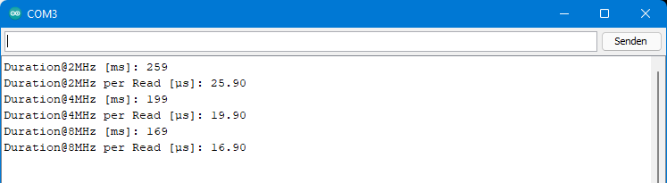
When using an ATmega328P-based board, you can achieve almost ten times the read rate by switching from the MCP23017 to the MCP23S17.
Reading out the Arduino’s own pins is still much faster. A digitalRead() only takes about 3.5 µs on the Arduino Nano. And reading out the PINB/PIND registers directly is even faster. This only takes about 0.44 µs. For details, see my post on port manipulation.
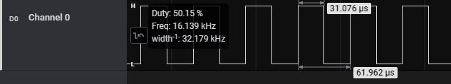
Maximum “toggle” speed
Last but not least, I tried to see how quickly a GPIO of the MCP23S17 can be switched back and forth between HIGH and LOW (“toggle”). I selected pin A1 and ran the following short sketch on the Arduino Nano:
#include <SPI.h>
#include <MCP23S17_WE.h>
#define CS_PIN 7   // Chip Select Pin
#define RESET_PIN 5
#define MCP_ADDRESS 0x20 // (A2/A1/A0 = LOW)

typedef MCP23S17_WE MCP;
MCP myMCP = MCP(CS_PIN, RESET_PIN, MCP_ADDRESS);

void setup(){
  Serial.begin(115200);
  SPI.begin();
  myMCP.Init();
  myMCP.setSPIClockSpeed(8000000);
  myMCP.setPinX(1, MCP::A, OUTPUT, LOW);
}

void loop(){
  myMCP.setPort(0b00000010, MCP::A);
  myMCP.setPort(0, MCP::A);
}
The maximum frequency is approximately 16 kHz. By comparison, digitalRead() achieves 127 kHz, and port manipulation even achieves approximately 2.3 MHz.
Wolfgang,
Not sure what is happening during port read, but it appears that MSBs get latched and not cleared from the GPIO registers. We are reading a rotary switch to select a hardware “channel” , one of four positions and should read 0b10000000, 0b01000000, etc. However, once “1” is present in the lesser bit, it remains as the switch is rotated to another position. Hence, returned value from port is 0b11000000, etc. if switch is rotated to a lesr position.
Code is: channel = myMCP.getPort(B); So channel variable returns decimal 240 if all four positions are read as switch is rotated.
Thoughts? I don’t want to hard reset after each read, soft reset does nothing.
Hi MarKo, are you using MCP23017 port expanders (in contrast to MCP23S17, MCP23S18 and MCP23018)? And have you bought these chips in 2022/2023? Then the bad news is that Microchip has changed the design of the MCP23017. GPA7 and GPB7 have lost their input function. They are output by default. You find this information in the MCP23017 section of this article. Extremely bad idea, no reason why they did this. And it’s also a risk: when these Pins are set LOW and you apply a positive voltage you produce a shortcut.
In theory, that shouldn’t impact GPA6/GPB6 which you are also using. Can you please try other pins, at least to test if the issue is related to new design or something else? If it still does not work with other pins, then I would ask you to try another library (e.g. the one from Adafruit). If this should work, then it’s something I might be able to change in the lib. Should the issue be the new version of the chip, then take other pins or take another MCP23x1y version.
Hi
The test code in library GPIO reading – have lines
myMCP.setPortMode(0b11111111, A); // Port A: all pins are OUTPUT
myMCP.setPortMode(0b11111111, B); // Port B: all pins are OUTPUT
myMCP.setPort(0b10010011,A); //
if all ports and pins are OUTPUT can we be able to test and read switch input on these ports ?
we not need INPUT on these ports if we connect switch ?
regards
ATHAR PAKISTAN
This is just to show if you set e.g. myMCP.setPort(0b10010011,A) and you query myMCP.getPort(A)that you will receive 0b1001011. If want to read external logic statusses all pins should be input.
Wolfgang
I understand well library GPIO reading code, i changed and performed the work again.
myMCP.setPortMode(0b00000000, A); // Port A: all pins are INPUT
myMCP.setPortMode(0b11111111, B); // Port B: all pins are OUTPUT
myMCP.setPort(0b00000000,A); //
myMCP.setPort(0b00000000,B); //
myMCP.setPortPullUp(0b00000000,A);
I have switch connected to PORT A from 0 to 7 and other + (HIGH) – A all INPUT and B all OUTPUT.
Module is following PCB
https://www.ebay.de/itm/264739247628?hash=item3da3b0560c:g:PSgAAOSwzStex51q
When i run sketch and operate switch it work fine few inputs and then some time stuck and then smooth but give false INPUT on nearby pins. If A3 is push it give A4 or A2 also HIGH.
Is there timing or speed of chip problem – how to control or do that so exact INPUT be monitor on switch.
What is function of PIN 5 reset and variable wT Wait. Reset to connect on pin 5 is necessary
Regards Athar Kaludi (UOK) Pakistan
Dear Athar,
why inputs on some pins lead to false results on neighbor pins is something I can’t tell you. At least this is not related with the library.
wT stands for waiting Time. My example sketch shows how LEDs are switched using the different functions. Some people might like to see the LEDs switching fast, some might like to perform it slowly, so that they can read the code and see the effect in parallel. So it is just for the example sketch.
The (hardware) reset is performed during init(). It ensures that alle registers are set back to default. Without a reset the registers would keep their settings as long as you do not disconnect the MCP23017 from power. That can lead to strange results, in particular when you develop sketches. In the newest version of the library, which I launched a week ago, you can just connect the reset Pin to HIGH, and pass a reset pin of 99 or a higher number like this:
#define RESET_PIN 99
…..
MCP23017 myMCP = MCP23017(MCP_ADDRESS, RESET_PIN)
Then library will then do a software reset as part of the init function, which means all registers are set to default by I2C/SPI commands.
Wolfdang
Thanks for quick reply – Well explained.
Taking grasp of things now, registers and other variables functions.
Reading Datasheet and your library have Interrupts.(Interrupts on change)
Is that meaning that any of the pin on any of MCP23017 GPIO when if used as INPUT via a [push button or touch switch or IR switch] will cause INT to feed to Arduino or MCU as soon as pin get change [Either Low to High OR High to Low]. We can write code in INT and compare with last state to know which pin caused or PUSH occurred where.
Is there any built-in way we know which pin cause Interrupt.
Any sketch you provided which use Interrupts change.
How to control speed of chip to use it in 100Khz.
Regards
Athar Kaludi
The use of interrupts is explained here:
https://wolles-elektronikkiste.de/en/port-expander-mcp23017-2?lang=en
Sorry, I can’t go more into details. Please have a look there.