
About this Post
In my post about the port expansion for the ESP-01 I had already briefly described the MCP23017, here I would like to go into detail about its many features. In the first part of this article, I would like to show you how to use the MCP23017 (and the MCP23S17) with the help of my library. The second part is a deep dive for those who are interested in the internal details. I will refer to the numerous registers of the MCP23017.
MCP23017 – an overview
The MCP23017 is a 16-bit I/O port expander with convenient interrupt functions. The 16 I/O pins are organized into two ports (A and B), which can be addressed separately (byte mode) or together (sequential mode). The supply voltage should be between 1.8 and 5.5 volts. The maximum current at the I/O pins is 25 mA in both directions. In total, the input current to VDD should not exceed 125 mA and not more than 150 mA should flow into VSS (GND). The communication protocoll is I²C. A data sheet for the MCP23017 can be found here.
In terms of its flexibility, the MCP23017 is the Swiss army knife among the common port expanders, if you compare it with the 74HC595 shift register or the PCF8574, for example.
Pinout of the MCP23017
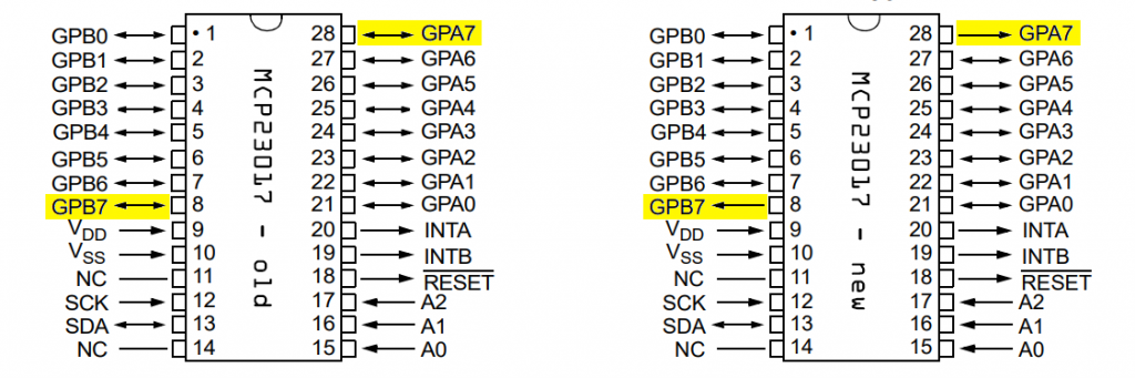
Important notice!!! The data sheet for the MCP23017 changed in 2022. According to the new version, pins GPA7 and GPB7 have lost their input function. The pins are now pure OUTPUT pins. Microchip appears to have responded to reported problems with this change. The problems may or may not occur. You can find a statement from Microchip on this here. Personally, I have not noticed any malfunctions so far.
The 16 I/O pins are named GPA0 to GPA7 or GPB0 to GPB7 according to the two ports. The power supply is via VDD and VSS. The connection of pins A0, A1 and A2 determines the I2C address according to the following scheme:
1 0 0 A2 A1 A0
For example, if A0 to A2 are LOW, then the address is 100000 (binary) = 32 (decimal) = 0x20 (hexadecimal). SDA and SCL are the two I²C pins. The reset pin is active-low. INTA and INTB are the interrupt pins for the two ports. You can set the polarity of the interrupt pins. You can also connect both interrupt pins together (mirror function).
Controlling the MCP23017 with the library
I have developed a library that you can find and download here on Github. You can also install the library directly from the Arduino IDE library manager. The library is designed so that the two ports, A and B, are addressed separately in byte mode. Perhaps I will expand the library to include sequential mode at some point.
Simple input/output applications
The functionality of the I/O pins is comparable to that of Arduino I/O pins. The pins can be used as inputs or outputs; they are switched to HIGH or LOW, and they can act as both current sources and current sinks. If they are set as input, the pins can serve as interrupt pins. But in the first example, we start easy, and only 16 LEDs are controlled.
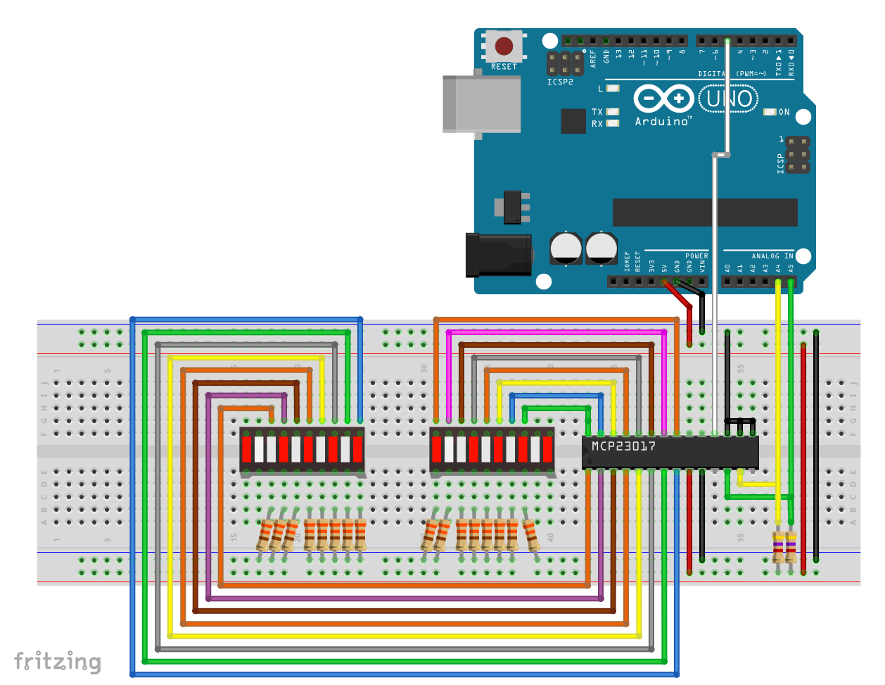
The address pins are set to LOW in my example circuit, so the I²C address is 0x20. The reset pin is connected to the Arduino pin 5. The pins of port A and B each control eight LEDs of an LED bar. The I²C lines SDA and SCL are equipped with pull-ups with 4.7 kOhm resistors. Without the pull-ups, however, it also worked well for me.
In this example, the following functions are used (the MCP23017 object is called myMCP here):
typedef MCP23017_WE MCP;is simply for convenience. Writing MCP instead of the class name MCP23017_WE requires less typing. I renamed the class with version 2.0.0 due to problems installing libraries with classes of the same name.MCP myMCP = MCP(MCP_ADDRESS, RESET_PIN)creates your MCP23017 object. You must pass the I²C address. You can also pass the reset pin and/or a wire object. With the latter, you can use both I²C buses of an ESP32, for example. You can also connect the reset pin to VDD to save a pin. However, you should then pass a dummy reset pin with a value of >= 99. This triggers a software reset instead of a hardware reset in Init().myMCP.Init();initializes the object with some default settings.myMCP.setPinMode( pin,port,direction );corresponds to the Arduino pinMode function, with the port added as a parameter here.- The port is A or B. I have defined the names in an enum. Since I have made the definition (since version 2.0.0) in the class, the class name must be prefixed (e.g.
MCP::A). This is one more argument for the abbreviation “MCP”. - Allowed identifiers for direction are: INPUT/OUTPUT/INPUT_PULLUP, OFF/ON or 0/1
- “0” = INPUT, “1” = OUTPUT.
- The port is A or B. I have defined the names in an enum. Since I have made the definition (since version 2.0.0) in the class, the class name must be prefixed (e.g.
myMCP.setPortMode( value,port );sets the pinMode for an entire port; value is best specified as a binary number.myMCP.setPortMode( value,port,INPUT_PULLUP);with this variant, all input pins get a pull-up; no effect on output pins.myMCP.setPin( pin,port,level );similar to the digitalWrite function;- allowed identifiers for level are: 0/1, OFF/ON, LOW/HIGH
myMCP.setPort( value,port );digitalWrite for the entire port; for me, binary numbers are more readable than decimal or hexadecimal numbers.myMCP.togglePin( pin,port );switches a pin from LOW to HIGH or from HIGH to LOW.myMCP.setPinX( pin,port,direction,level );“Extended version” of the setPin function or combination of setPinMode and setPin.myMCP.setPortModeX( direction,value,port );“Extended version” of the setPort function.myMCP.setAllPins( port,level );sets all pins of a port to LOW or HIGH.
A complete list of all library functions can be found here.
Sample sketch for simple output applications
Here is a sketch that plays with these functions and hopefully illustrates them:
#include <Wire.h>
#include <MCP23017_WE.h>
#define MCP_ADDRESS 0x20 // (A2/A1/A0 = LOW)
/* A hardware reset is performed during init(). If you want to save a pin you can define a dummy
 * reset pin >= 99 and connect the reset pin to HIGH. This will trigger a software reset instead
 * of a hardware reset.
 */
#define RESET_PIN 5

typedef MCP23017_WE MCP; // just for less typing!

/* There are several ways to create your MCP23017 object:
 * MCP23017_WE myMCP = MCP23017_WE(MCP_ADDRESS) -> uses Wire / no reset pin
 * MCP23017_WE myMCP = MCP23017_WE(MCP_ADDRESS, RESET_PIN) -> uses Wire / RESET_PIN
 * MCP23017_WE myMCP = MCP23017_WE(&Wire, MCP_ADDRESS) -> passing a TwoWire object / no reset pin
 * MCP23017_WE myMCP = MCP23017_WE(&Wire, MCP_ADDRESS, RESET_PIN) -> "all together"
 */
MCP myMCP = MCP(MCP_ADDRESS, RESET_PIN); // short version
// MCP23017_WE myMCP = MCP23017_WE(MCP_ADDRESS, RESET_PIN); // long version

int wT = 1000; // wT = waiting time

void setup(){
  Serial.begin(9600);
  Wire.begin();
  if(!myMCP.Init()){
    Serial.println("Not connected!");
    while(1){}
  }
  myMCP.setPortMode(0b11111101, MCP::A);  // Port A: all pins are OUTPUT except pin 1
  myMCP.setPortMode(0b11111111, MCP::B);  // Port B: all pins are OUTPUT
  delay(wT);
  myMCP.setAllPins(MCP::A, HIGH); // alle LEDs switched on except A1
  delay(wT);
  myMCP.setPinX(1, MCP::A, OUTPUT, HIGH); // A1 switched on
  delay(wT);
  myMCP.setPort(0b11110000, MCP::B); // B4 - B7 switched on
  delay(wT);
  myMCP.setPort(0b01011110, MCP::A); // A0,A5,A7 switched off
  delay(wT);
  myMCP.setPinX(0, MCP::B, OUTPUT, HIGH); // B0 switched on
  delay(wT);
  myMCP.setPinX(4, MCP::B, OUTPUT, LOW); // B4 switched off
  delay(wT);
  myMCP.setAllPins(MCP::A, HIGH); // A0 - A7 all on
  delay(wT);
  myMCP.setPin(3, MCP::A, LOW); // A3 switched off
  delay(wT);
  myMCP.setPortX(0b11110000, 0b01101111, MCP::B); // at port B only B5,B6 are switched on
  delay(wT);
  myMCP.setPinMode(0, MCP::B, OUTPUT); // B0 --> OUTPUT
  for(int i=0; i<5; i++){  // B0 blinking
    myMCP.togglePin(0, MCP::B);
    delay(200);
    myMCP.togglePin(0, MCP::B);
    delay(200);
  }
  for(int i=0; i<5; i++){ // B7 blinking
    myMCP.togglePin(7, MCP::B);
    delay(200);
    myMCP.togglePin(7, MCP::B);
    delay(200);
  }
}

void loop(){
}
In my example, the current (technical current direction) flows from the MCP23017 through the LEDs to GND. Instead, the MCP23017 could, of course, also be used as a current sink. Then an LED would light up if the corresponding pin is OUTPUT and LOW and voltage is supplied, comparable with how the Arduino works.
Read pin status
The following functions are used to read the pin status in the GPIO register:
myMCP.getPin( pin,port );returns the level of a pin (as a boolean).myMCP.getPort( port );returns the status of an entire port (as uint8_t), i.e. the contents of the GPIO register.
Here is an example circuit for you:
And here is the corresponding example sketch:
#include <Wire.h>
#include <MCP23017_WE.h>
#define MCP_ADDRESS 0x20 // (A2/A1/A0 = LOW)

/* A hardware reset is performed during init(). If you want to save a pin you can define a dummy
 * pin >= 99 and connect the reset pin to HIGH. This will trigger a software reset instead of a
 * hardware reset.
 */
#define RESET_PIN 5

typedef MCP23017_WE MCP; // just for less typing!

/* There are several ways to create your MCP23017 object:
 * MCP23017_WE myMCP = MCP23017_WE(MCP_ADDRESS) -> uses Wire / no reset pin
 * MCP23017_WE myMCP = MCP23017_WE(MCP_ADDRESS, RESET_PIN) -> uses Wire / RESET_PIN
 * MCP23017_WE myMCP = MCP23017_WE(&Wire, MCP_ADDRESS) -> passing a TwoWire object / no reset pin
 * MCP23017_WE myMCP = MCP23017_WE(&Wire, MCP_ADDRESS, RESET_PIN) -> "all together"
 */
MCP myMCP = MCP(MCP_ADDRESS, RESET_PIN); // short version
// MCP23017_WE myMCP = MCP23017_WE(MCP_ADDRESS, RESET_PIN); // long version

int wT = 1000; // wT = waiting time
byte portStatus;
bool pinStatus;

void setup(){
  Serial.begin(9600);
  Wire.begin();
  if(!myMCP.Init()){
    Serial.println("Not connected!");
    while(1){}
  }
  myMCP.setPortMode(0b00000000, MCP::A);  // Port A: all pins are INPUT
  myMCP.setPortPullUp(0b11110000, MCP::A);  // Port A: Pin 4 - 7 are pulled up
}

void loop(){

  portStatus = myMCP.getPort(MCP::A); // query the complete port status
  Serial.print("Status GPIO A: ");
  Serial.println(portStatus, BIN);

  pinStatus = myMCP.getPin(5, MCP::A); // query one pin status
  Serial.print("Status Port A, Pin 5: ");
  Serial.println(pinStatus, BIN);

  Serial.println("-------------------------------------");
  delay(1000);
}
I/Os configured as INPUT can get an internal pull-up:
myMCP.setPinPullUp( pin,port );sets a pull-up with a 100 kOhm resistormyMCP.setPortPullUp( value,port );is the equivalent for an entire port
You must add pull-down resistors externally.
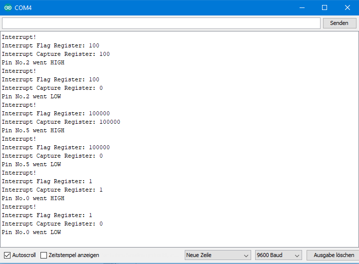
This is what the output of the example sketch looks like:

Interrupt-on-Change
All 16 I/O pins can be configured as interrupt pins. There are two modes, the interrupt-on-change and the interrupt-on-defval-deviation. I start with the interrupt-on-change function, where every switch from LOW to HIGH or HIGH to LOW triggers an interrupt. The interrupt induces a polarity change at the respective interrupt output INTA or INTB. Alternatively, you can merge INTA and INTB. You can also set the polarity of the interrupt outputs.
Only pins set as INPUT can act as interrupt pins, but this setting is done in the background by the library.
I have implemented the following functions for interrupt-on-change:
myMCP.setInterruptOnChangePin( pin,port );sets up a single pin as an interrupt-on-change pin.myMCP.setInterruptOnChangePort( value,port );configures several or all pins of a port as interrupt-on-change pins.myMCP.setInterruptPinPol( level );sets the level of the active interrupt output- level = HIGH –> active-high, level = LOW → active-low (default).
- I have only implemented one setting for both outputs, i.e. both active-high or both active-low.
myMCP.setIntOdr( value );value = 1 or ON → Interrupt outputs go into open drain state, interrupt pin polarity is overwritten; value = 0 or OFF → active-low or active-high (both).myMCP.deleteAllInterruptsOnPort( port );resets the configuration of the interrupt pins.myMCP.setIntMirror ( value );value = 1 or ON → INTA / INTB are mirrored, value = 0 or OFF → INTA / INTB are responsible for their ports separately (default setting).myMCP.getIntFlag( port );returns the value of the interrupt flag register as a byte (uint8_t). The bit representing the pin responsible for the last interrupt is set in the interrupt flag register.myMCPgetIntCap( port );returns the value of the interrupt capture register. It contains the value of the GPIO register at the time of the interrupt.
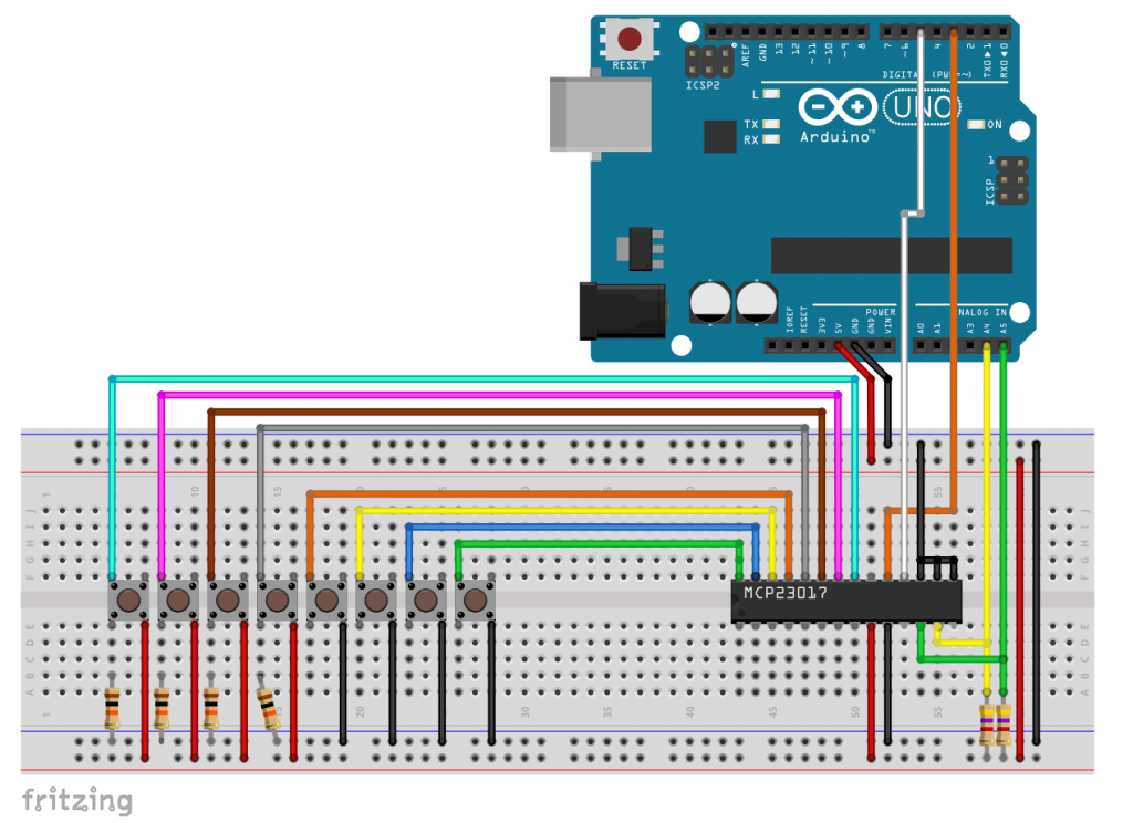
For testing, I have set up the following circuit:

The pins of port B are set up as interrupt pins and receive HIGH signals via the buttons. The LEDs connected to port A should indicate which pin the interrupt occurred on.
Example sketch for interrupt-on-change
#include <Wire.h>
#include <MCP23017_WE.h>
#define MCP_ADDRESS 0x20 // (A2/A1/A0 = LOW)
/* A hardware reset is performed during init(). If you want to save a pin you can define a dummy
 * reset pin >= 99 and connect the reset pin to HIGH. This will trigger a software reset instead
 * of a hardware reset.
 */
#define RESET_PIN 5
int interruptPin = 3;
volatile bool event;

typedef MCP23017_WE MCP; // just for less typing!

/* There are several ways to create your MCP23017 object:
 * MCP23017_WE myMCP = MCP23017_WE(MCP_ADDRESS) -> uses Wire / no reset pin
 * MCP23017_WE myMCP = MCP23017_WE(MCP_ADDRESS, RESET_PIN) -> uses Wire / RESET_PIN
 * MCP23017_WE myMCP = MCP23017_WE(&Wire, MCP_ADDRESS) -> passing a TwoWire object / no reset pin
 * MCP23017_WE myMCP = MCP23017_WE(&Wire, MCP_ADDRESS, RESET_PIN) -> "all together"
 */
MCP myMCP = MCP(MCP_ADDRESS, RESET_PIN); // short version
// MCP23017_WE myMCP = MCP23017_WE(MCP_ADDRESS, RESET_PIN); // long version


void setup(){
  pinMode(interruptPin, INPUT);
  attachInterrupt(digitalPinToInterrupt(interruptPin), eventHappened, RISING);
  Serial.begin(9600);
  Wire.begin();
  if(!myMCP.Init()){
    Serial.println("Not connected!");
    while(1){}
  }
  myMCP.setPortMode(0b11111111, MCP::A);
  myMCP.setPort(0b11111111, MCP::A); // just an LED test
  delay(1000);
  myMCP.setAllPins(MCP::A, LOW);
  delay(1000);
  myMCP.setInterruptPinPol(HIGH); // set INTA and INTB active-high
  delay(10);
  myMCP.setInterruptOnChangePort(0b11111111, MCP::B); //set all B pins as interrrupt Pins
  delay(10);
  myMCP.getIntCap(MCP::B); // ensures that existing interrupts are cleared
  event=false;
}

void loop(){
  if(event){
    byte intFlagReg = myMCP.getIntFlag(MCP::B);
    byte eventPin = log(intFlagReg)/log(2);
    byte intCapReg = myMCP.getIntCap(MCP::B);
    Serial.println("Interrupt!");
    Serial.print("Interrupt Flag Register: ");
    Serial.println(intFlagReg, BIN);
    Serial.print("Interrupt Capture Register: ");
    Serial.println(intCapReg, BIN);
    Serial.print("Pin No.");
    Serial.print(eventPin);
    Serial.print(" went ");
    if((intFlagReg&intCapReg) == 0){  //LOW-HIGH or HIGH-LOW interrupt?
      Serial.println("LOW");
    }
    else{
      Serial.println("HIGH");
    }
    myMCP.setPort(intFlagReg, MCP::A);
    delay(200);
    intCapReg = myMCP.getIntCap(MCP::B);
    event = false;
  }
}

void eventHappened(){
  event = true;
}
Note 1: Pressing the button briefly (< 200 ms) triggers a LOW-HIGH interrupt; pressing and holding the button triggers first a LOW-HIGH interrupt and then a HIGH-LOW interrupt.
Note 2: The interrupt remains active until a getIntCap or getPort query is performed. When things go bad because you query at the wrong time or the next interrupt comes at the wrong time, the interrupt will remain unintentional active. That is why I added an additional getIntCap query in line 67, which may seem redundant at first glance. This ensures that the MCP23017 is ready for the next interrupt.
Interrupt-on-DefVal-Deviation
Here, the polarity of the interrupt pins is compared with the state defined in the so-called DEFVAL register. A deviation triggers an interrupt. If you read the interrupt capture or GPIO register, you delete the interrupt. However, if the interrupt condition is still met at this time, the next interrupt is triggered immediately.
For this interrupt method, I have implemented the following additional functions:
myMCP.setInterruptOnDefValDevPin( intpin,port,defvalstate );intpin is the interruptpin, defvalstate is the default level and a deviation from it leads to the interruptmyMCP.setInterruptOnDefValDevPort( intpins,Port,defvalstate );- intpins are the interruptpins, e.g. B10000001 would set the pins 0 and 7 as interrupt pins.
- defvalstate is the value of the DEFVAL register; a deviation leads to the interrupt
As an example, I have set up the following circuit:

The port B pins are defined as interrupt pins. B0 to B3 are set HIGH with internal pull-ups, while B4 to B7 get pull-down resistors. The polarity on the respective pin is reversed by pushing the button. As in the last example, port A is again used to display the pin responsible for the interrupt.
Example sketch for interrupt-on-defval-deviation
#include <Wire.h>
#include <MCP23017_WE.h>
#define MCP_ADDRESS 0x20 // (A2/A1/A0 = LOW)
/* A hardware reset is performed during init(). If you want to save a pin you can define a dummy
 * reset pin >= 99 and connect the reset pin to HIGH. This will trigger a software reset instead
 * of a hardware reset.
 */
#define RESET_PIN 5
int interruptPin = 3;
volatile bool event = false;
uint8_t defValB = 0b00001111; // if port B deviates, an interrupt is triggered

typedef MCP23017_WE MCP; // just for less typing!

/* There are several ways to create your MCP23017 object:
 * MCP23017_WE myMCP = MCP23017_WE(MCP_ADDRESS) -> uses Wire / no reset pin
 * MCP23017_WE myMCP = MCP23017_WE(MCP_ADDRESS, RESET_PIN) -> uses Wire / RESET_PIN
 * MCP23017_WE myMCP = MCP23017_WE(&Wire, MCP_ADDRESS) -> passing a TwoWire object / no reset pin
 * MCP23017_WE myMCP = MCP23017_WE(&Wire, MCP_ADDRESS, RESET_PIN) -> "all together"
 */
MCP myMCP = MCP(MCP_ADDRESS, RESET_PIN); // short version
// MCP23017_WE myMCP = MCP23017_WE(MCP_ADDRESS, RESET_PIN); // long version

void setup(){
  pinMode(interruptPin, INPUT);
  attachInterrupt(digitalPinToInterrupt(interruptPin), eventHappened, RISING);
  Serial.begin(9600);
  Wire.begin();
  if(!myMCP.Init()){
    Serial.println("Not connected!");
    while(1){}
  }
  myMCP.setPortMode(0b11111111, MCP::A);
  myMCP.setPort(0b11111111, MCP::A); // just an LED test
  delay(1000);
  myMCP.setAllPins(MCP::A, LOW);
  delay(1000);
  myMCP.setInterruptPinPol(HIGH);
  delay(10);
  myMCP.setInterruptOnDefValDevPort(0b11111111, MCP::B, defValB); // interrupt pins, port, DEFVALB
  myMCP.setPortPullUp(0b00001111, MCP::B); // pull-up for B0-B3
  delay(10);
  myMCP.getIntCap(MCP::B); // deletes all interrupts
  event = false;
}

void loop(){
  if(event){
    byte intFlagReg = myMCP.getIntFlag(MCP::B);
    byte eventPin = log(intFlagReg)/log(2);
    byte intCapReg = myMCP.getIntCap(MCP::B);
    Serial.println("Interrupt!");
    Serial.print("Interrupt Flag Register: ");
    Serial.println(intFlagReg, BIN);
    Serial.print("Interrupt Capture Register: ");
    Serial.println(intCapReg, BIN);
    Serial.print("Pin No.");
    Serial.print(eventPin);
    Serial.print(" went ");
    if((intFlagReg&intCapReg) == 0){ // HIGH/LOW or LOW/HIGH change?
      Serial.println("LOW");
    }
    else{
      Serial.println("HIGH");
    }
    myMCP.setPort(intFlagReg, MCP::A);
    delay(400);
    /* if you use a pushbutton to trigger the interrupt, uncomment the
       following line. */
    // while(myMCP.getPort(MCP::B) != defValB) {} // while key is pressed
    intCapReg = myMCP.getIntCap(MCP::B);
    event = false;
  }
}

void eventHappened(){
  event = true;
}
The crucial difference to interrupt-on-change is that in this method the polarity change leads only in one direction to the interrupt. The output looks like this:

The MCP23S17
The MCP23S17 differs from the MCP23017 only in that it is controlled via SPI instead of I2C. This means that the connections are slightly different. All functions are identical. You can find a sample sketch and the corresponding wiring in my library.
MCP23017 / MCP23S17 internal
Here, as announced, some additional detailed information about the MCP23017 for those who still want it.
The MCP23017 is only a representative of the larger MCP23XXX family, which differ from each other in the number of I/O pins, the control (I2C vs SPI) and the external connection. The MCP23017 is probably the most popular representative. I have written a separate article about the others, which you can find here.
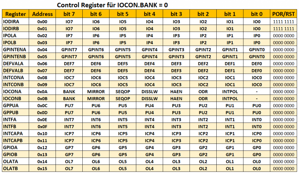
The registers of the MCP23017
First of all, you have to decide how to address the registers. For this, you can set the BANK bit in the IOCON Register. If this is set to 1, the port registers are in two separate banks. If, on the other hand, it is set to 0, the registers are located in the same bank, and the addresses are sequential. I opted for the latter and did not implement the alternative as an option. The registers are thus defined as follows:
IODIR – I/O direction register
The IODIR register determines whether the pins are INPUT or OUTPUT pins. It is the only register with a start or reset value of 0b11111111. “1” means INPUT, “0” means OUTPUT, which sounds illogical to me, but maybe I am just used to the different definition in the world of Arduino. But because this irritates me, I have turned the values in my library accordingly. WithmyMCP.setPortMode() and myMCP.setPinMode() the IODIR register is addressed directly. For example, myMCP.setPortMode(B11111111, A) means that all pins of the port are OUTPUT pins.
IPOL – input polarity register
If you set the bits in this register, the inverted level of the pins is stored in the corresponding GPIO register.
GPINTEN – Interrupt-on-Change control register
This register controls which pins are used as interrupt pins. 0 = disable, 1 = enable. If you only want to implement interrupt-on-change, no further settings are necessary. However, in case you want to implement interrupt-on-defval-deviation, you have to make additional settings in the DEFVAL and INTCON registers. The GPINTEN register is accessed indirectly in my library via the setInterruptOnChangePin() and setInterruptOnDefValDevPin() functions or their counterparts for entire ports.
DEFVAL – default value register
This register is required to set up Interrupts-on-Defval-Deviation. If a value in the GPIO register differs from the DEFVAL register, an interrupt is triggered if the corresponding settings have been made in the GPINTEN and INTCON registers.
INTCON – interrupt control register
This register determines the conditions under which interrupts are triggered:
- “0”: Comparison with previous pin status (interrupt-on-change)
- “1”: Comparison with DEFVAL (Interrupt-on-DefVal-Deviation)
However, the settings are only effective on the pins for which the corresponding bits have been set in GPINTEN.
IOCON – I/O expander configuration register

In this register, some special settings can be made for the MCP23017.
- BANK – Addressing mode for the registers
- “1”: registers are in separate banks
- “0”: registers are in the same bank
- I did not implement an option to change that in my library
- MIRROR – is adjustable in my library via setIntMirror()
- “1”: INTA and INTB are connected (mirrored)
- “0”: INTA and INTB are separately responsible for port A and B respectively
- SEQOP – sequential addressing
- “1”: disabled – the address pointer is not incremented
- “0”: enabled – the address pointer is automatically incremented
- I did not implement an option to change that in my library
- DISSLW – Adjustment of the slope of the SDA output
- “1”: disabled
- “0”: enabled
- not implemented in my library
- HAEN – not relevant for the MCP23017
- ODR – open drain for the interrupt pins INTA and INTB
- “1”: open drain is active – overrides the INTPOL setting
- “0”: disabled – polarity of the interrupt signal is determined by INTPOL
- setting is done via setIntODR(); only one common setting for both pins is implemented in my library (either both 0 or both 1)
- INTPOL – polarity of interrupt pins
- “1”: active-high
- “0”: active-low
- in my library only one common setting of both pins is implemented
- GPPU – GPIO pull-up register
- “1”: pull-up with 100 kOhm resistor
- “0”: no pull-up
- implemented in my library by setPinPullUp() or setPortPullUp()
- impacts only pins configured as input
INTF – interrupt flag register (read-only)
This register records which pin caused the last interrupt. The set bit reveals the “guilty” one. In my library, getIntFlag() queries the register content.
INTCAP – interrupt capture value register (read-only)
This register records the contents of the GPIO register at the time of the last interrupt. I implemented the query through the getIntCap() function.
GPIO – general purpose I/O port register
Contains the pin status (HIGH/LOW). In my library, the GPIO register is not written to directly, but via the OLAT (Output Latch) register. Read access in my library is performed via getPin() or getPort().
OLAT – output latch register
Reading gives you the state of the register, not the port’s state (this would be done through the GPIO Read). This means, for example, if a pin is set as LOW, but an external HIGH is attached, then you will read it as LOW here, whereas in the GPIO register you would read it as HIGH.
Hi Wolgang,
Would it be possible to access the IPOLA and IPOLB registers via the library?
Regards.
Hi Robert, since few minutes you can. I added a function setIpol(value, port). So, for example: myMCP.setIpol(0b11110000, A);
Version 1.6.12 – should be available via the Arduino IDE in a few hours, or you can download it from GitHub now.
Regards, Wolfgang
Vielen Dank für Ihre schnelle Antwort und die zügige Bearbeitung. Ich weiß das sehr zu schätzen, da ich Deine Bibliothek ausschließlich für meine Entwicklungsarbeit verwende.
Gern geschehen!
Hi, danke für diese tolle Bibliothek!
Wissen Sie ob man die Bibliothek mit einem ESP32 nutzen kann?
Wenn es nicht funktioniert, welche Änderungen müssten durchgeführt werden um es mit einem ESP32 nutzen zu können?
Mit freundlichen Grüßen,
Fazeli24
Hi, ja sie funktioniert auch mit einem ESP32. Getestet auf einem ESP32 Development Board. Für mcp23017_basic_input_output.ino sind keine Änderungen des Codes notwendig. Hardwareseitig sind natürlich die ESP32 I2C Pins zu nehmen. Meistens sind das GPIO21 (SDA) und GPIO22 (SCL). Wenn der MCP23017 mit 5V versorgt wird, braucht man streng genommen Spannnungsteiler oder Levelshifter für die I2C-Leitungen, um sie auf 3.3 Volt zu bringen. Kein Problem bei 3.3 Volt Versorgung. Bei den Sketchen mit Interruptnutzung ist zu beachten, dass die ISR (also die Funktion, die im Falle des Interrupts aufgerufen wird) das IRAM_ATTR erfordert, also zum Beispiel:
void IRAM_ATTR eventHappened(){….}
Ferner müssen ISRs “nach oben” wandern, sprich vor dem setup() Teil stehen.
Mehr fällt mir nicht ein. Wenn etwas nicht geht, dann brauche ich genaue Informationen. Wie genau macht sich der Fehler bemerkbar, welcher Sketch / was verändert, welches ESP32 Board, wie verbunden.
VG, Wolfgang
Hello.
Is it possible to add a registry dump function to the library? Could be useful for debug.
Hi Robert, you mean a function to read specific registers or all registers in one go? I just want to be sure that I understood the request correctly.
In one go only those used in the library.
Thank you already for your work.
I have added a function called printAllRegisters(). It requires quite some SRAM and Flash. Therefore, I have added a debug mode which you need to activate to be able to use the function. To do so, you go into the library file MCP23017_config.h and uncomment line seven:
#define DEBUG_MCP23017.
Since I use at least two thirds of the registers, I decided to print them all.
The new release is 1.6.6. You can download it from GitHub now, or you wait until it’s made available in the Arduino IDE which usually takes up to 24 h.
Hi Wolfgang.
Great thank you for your responsiveness. I’m interested in interrupts and their configuration is not simple, hence my proposal. This will help me a lot.
King regards.
Robert.
Na ja, jetzt auf Deutsch, das passt mir auch gut.
Ich habe mir die Dateien in Ihrer Bibliothek angesehen und habe einen Vorschlag für den Anfang der Header-Datei.
public:
/* Bank 0 registers */
static constexpr uint8_t IODIRA {0x00};
static constexpr uint8_t IODIRB {0x01};
static constexpr uint8_t IPOLA {0x02};
static constexpr uint8_t GPINTENA{0x04};
static constexpr uint8_t GPINTENB{0x05};
static constexpr uint8_t DEFVALA {0x06};
static constexpr uint8_t DEFVALB {0x07};
static constexpr uint8_t INTCONA {0x08};
static constexpr uint8_t INTCONB {0x09};
static constexpr uint8_t IOCONA {0x0A};
static constexpr uint8_t IOCONB {0x0B};
static constexpr uint8_t GPPUA {0x0C};
static constexpr uint8_t GPPUB {0x0D};
static constexpr uint8_t INTFA {0x0E};
static constexpr uint8_t INTFB {0x0F};
static constexpr uint8_t INTCAPA {0x10};
static constexpr uint8_t INTCAPB {0x11};
static constexpr uint8_t GPIOA {0x12};
static constexpr uint8_t GPIOB {0x13};
/* Bits in IOCON registers */
static constexpr uint8_t INTPOL {0x01};
static constexpr uint8_t INTODR {0x02};
static constexpr uint8_t MIRROR {0x06};
/* Miscellaneous for SPI interface (MCP23S17)*/
static constexpr uint8_t SPI_READ{0x01};
mfg
Robert.
Vielen Dank!
Thanks, valid point. I will apply it in the next update. The headline “Registers” for all was misleading.
Hello and thank you for your work, could you help me please. I can’t make a program. what I want. 1 press button high, the LED lights up and stays on. On the 2nd press button high, the LED off . thanks in advance
Hi athys,
that’s basically no problem. Have you tried and failed? In that case it would be helpful to know what you did and what the failure was. In case you don’t know at all what to do: Just connect the push-button to one of the mcp23017 pins. The pin must be input. Then you have two options:
1) you activate the internal pullup and connect the other side of the push-button to GND.
2) you set the pin to input low and connect the other side to VCC level. In that case you have to add an additional pull-down resistor (10 kohms). to the pin.
Then you request the pin state in a loop. When it changes you toggle the level of another pin at which you have the LED connected. That pin needs to be in output mode.
One additional problem you have to solve is the bouncing of the push-button. If you press a button it usually goes high and low several times within few seconds. The simples way to overcome that issue is to add a delay of 20 to 200 milliseconds. You can google “debouncing”.
However, the best solution to achieve what you want to do is to use an interrupt to monitor the level of the pin connected to the push-button. The advantage is that you do not have to request the pin level all the time. But I recommend to first try the first option. If it works you can bring it to the next level.
Hope this helps. If not, then please specify the issue.
Regards, Wolfgang
Hi. Thanks for posting. I’m in a deliberate dilemma of wanting to expand the ESP32’s digital ports and connect to the network via RJ45 cable.
First I installed the MCP23017 port expander including more than one (1) (Thus identifying the addresses) and it simply worked well with the example codes from the Adafruit-MCP23017 library itself.
Separately, I configured the ENC28J60 shield to connect the esp32 to the network using the cable. Luckily I also managed to get it working.
Finally I wanted to put together the codes so that I could control the inputs and outputs (Buttons and LEDs) and also through the home assistant via mqtt. I was only able to make the buttons and LEDs connected directly to the ESP32 work, I can control the LEDs through the buttons as well as through the home assistant via mqtt.
The problem now is to control the LEDs connected to the GPIO expander. They don’t trigger anything. Neither through the home assistant nor through the buttons. The buttons connected to the expanders also show no effect when pressed. I was supposed to see it through the serial monitor, in the same way I see those connected to the ESP32.
#include
#include
#include
#include
#include
#include
// Instanciar objeto mcp
Adafruit_MCP23X17 mcp1;
Adafruit_MCP23X17 mcp2;
// Definir o endereço MAC e IP para o ENC28J60
byte mac[] = {0xDE, 0xAD, 0xBE, 0xEF, 0xFE, 0xED};
IPAddress ip(192, 168, 1, 177);
// //Definir detalhes do MQTT broker
const char* mqtt_server = “192.168.1.29”;
const int mqtt_port = 1883;
const char* mqtt_username = “mqtt_user”;
const char* mqtt_password = “mqtt_pass”;
// Define GPIO pins
const int lampada_varanda = 2;
const int interruptor_varanda = 4;
const int interruptor_sala_de_estar = 0;
const int lampada_sala_de_estar = 0;
int lampada_varandaValue = LOW;
int lampada_sala_de_estarValue = LOW;
EthernetClient ethClient;
PubSubClient client(ethClient);
void callback(char* topic, byte* payload, unsigned int length) {
// lidar com a mensagem chegou
String content = “”;
char character;
for (int num = 0; num < length; num++) {
character = payload[num];
content.concat(character);
}
Serial.println(topic);
Serial.println(content); // Mensagens enviadas por ações de botõo são retornadas pelo broker e impressas no monitor serial
if (content == "1on") {
lampada_varandaValue = HIGH;
}
if (content == "1off") {
lampada_varandaValue = LOW;
}
if (content == "2on") {
lampada_sala_de_estarValue = HIGH;
}
if (content == "2off") {
lampada_sala_de_estarValue = LOW;
}
digitalWrite(lampada_varanda, lampada_varandaValue);
digitalWrite(lampada_sala_de_estar, lampada_sala_de_estarValue);
}
Bounce bouncer1 = Bounce();
Bounce bouncer2 = Bounce();
void setup() {
// Iniciar o Moitor Serial
Serial.begin(115200);
Wire.begin();
// Inicializar as instâncias dos MCP23017
if (!mcp1.begin_I2C(0x20)) {
Serial.println("Erro ao inicializar o MCP23017 1. Por favor, verifique as conexções.");
while (1);
}
if (!mcp2.begin_I2C(0x21)) {
Serial.println("Erro ao inicializar o MCP23017 2. Por favor, verifique as conexções.");
while (1);
}
// Setup Ethernet
Ethernet.begin(mac, ip);
// Setup MQTT
client.setServer(mqtt_server, mqtt_port);
client.setCallback(callback);
// Setup GPIO
pinMode(lampada_varanda, OUTPUT);
pinMode(interruptor_varanda, INPUT_PULLUP);
digitalWrite(interruptor_varanda, HIGH);
bouncer1.attach(interruptor_varanda);
bouncer1.interval(5);
mcp1.pinMode(interruptor_sala_de_estar, INPUT);
mcp2.pinMode(lampada_sala_de_estar, OUTPUT);
digitalWrite(interruptor_sala_de_estar, HIGH);
bouncer2.attach(interruptor_sala_de_estar);
bouncer2.interval(5);
}
void loop() {
// ConnectConectar ao MQTT
if (!client.connected()) {
reconnect();
}
//Lidando com as mensagens do mqtt broker de novo
client.loop();
if (bouncer1.update()) {
if (bouncer1.read() == HIGH) {
if (lampada_varandaValue == LOW) {
lampada_varandaValue = HIGH;
client.publish("casa/interruptores/varanda", "1on");
} else {
lampada_varandaValue = LOW;
client.publish("casa/interruptores/varanda", "1off");
}
}
}
int buttonState = mcp1.digitalRead(interruptor_sala_de_estar);
if (bouncer2.update()) {
if (bouncer2.read() == HIGH) {
if (lampada_sala_de_estarValue == LOW) {
lampada_sala_de_estarValue = HIGH;
client.publish("casa/interruptores/sala_estar", "2on");
} else {
lampada_sala_de_estarValue = LOW;
client.publish("casa/interruptores/sala_estar", "2off");
}
}
}
}
void reconnect() {
// Repetição até se conectar
while (!client.connected()) {
Serial.println("Tentando conectar ao servidor MQTT…");
// Tentativa de conecxão
if (client.connect("ESP32Client", mqtt_username, mqtt_password)) {
Serial.println("Conectado");
// Subcrevendo – se ao tópico (se Necessário)
client.subscribe("casa/interruptores/#");
} else {
Serial.print("Falha ao conectar, rc= ");
Serial.println(client.state());
Serial.println("Tentar de novo em 5 segundos");
// Esperar 5 segundos antes de tentar outra vez
delay(5000);
}
}
}
If anyone can take a look at my code and help me understand where I'm going wrong. It's a project to automate my home.
Hugs.
Dércio
Hi Dércio,
to me it seems you are mixing code for the Arduino GPIOs and the MCP23017 GPIOs. E.g.:
pinMode(interruptor_varanda, INPUT_PULLUP); // this addresses an Arduino Pin
digitalWrite(interruptor_varanda, HIGH); // this addresses an Arduino Pin and you should not set the pin high because you already used INPUT_PULLUP
mcp1.pinMode(interruptor_sala_de_estar, INPUT); // This addresses an MCP23017 pin
digitalWrite(interruptor_sala_de_estar, HIGH); // This addresses an Arduino Pin
If you want to set the pinMode of interruptor_sala_de_estar to INPUT/ HIGH, you need to use:
mcp1.pinMode(interruptor_sala_de_estar, INPUT_PULLUP);
It could be that this is not the only issue.
Looks like a very nice library, and I’d love to use it with the raspberry pi pico (rp2040) board. Do you have any plans to extend your library to work with the pico?
best!
kb
I don’t say no, but to be honest I have no near term plans to do so. The resource I am lacking is time! I have already “translated” my library for the ADS1115 into Micropython. That was fun to do, but I know from that experience that it is quite an effort.
Thank you for this post, Wolf. It was very useful for my home project.
Specifically, Microchip’s documentation is unclear about how the latch register works. Your explanation is better.
Cheers! …from the Sierra Foothills of California
Thanks for this motivating comment! It’s great to get feedback from so far away. Greetings from Germany to California! Best wishes, Wolfgang
Wolfgang Ewald
Many thanks for replies.
One query arise relate to Interrupt On Change.
If we use all features and enable Interrupt On Change & other registers of MCP23017 and corresponding pins
and not enable ISR or Attach Interrupt in Arduino code at all.
We plan to deal only in LOOP().
Will the register return the result of both corresponding register.
For how much time that stay in register and when are they cleared.
Regards
Athar
The data sheet says for the INTCAP registers:
The register remains unchanged until the interrupt is cleared via a read of INTCAP or GPIO.
For the INTF (Interrupt Flag) registers it doesn’t say anything. I assume it’s cleared when you read it. Just try I would say.
Wolfgang
INTCAP & INTF are cleared upon read. Well understood. Inturrupt Capture – Inturrupt Flag
Can you brief me in your words as:
When I press Switch on A at PIN 0.
What happen to INTCAP (0x10 ) and INTF (0xE) before & after.
Before and after.
What are their exact Values before the push event and what is after event in both registers. and what value after i read them via READ command as cleared.
Regards
Athar Kaludi – PAKISTAN
Hi,
INTFA will be 1 (0b00000001), provided the pin A0 is set up as an interrupt pin. If you pressed a switch at A1, INTFA would be 2 (0b00000010), for A2 it would be 4 (0b00000100) and so on.
The INTCAPA register records the content of the GPIO register at the time of the last interrupt. Therefore I can’t tell what the bits 1-7 would look like. It depends on what is connected to the these or if you have set them up to be LOW or HIGH. Pressing Switch A0 will only affect bit 0 of INTCAPA. If the switch provides a HIGH signal then bit 0 will be 1, if it provides a LOW signal then it will be 0.
My recommendation: Try and play. It’s no big effort.
Thanks Wolfgang
Your Output and my output on Serial monitor differ in both programs.
On Change and On Defval. It false take values and input even not touch switches ?
Any Idea ?
Regards
Athar
Module is using RESET tied HIGH and connected permanent on 5 volts
I need more information. What do you mean with “both programs”? Which ones? When you say “your output and my output”, which ones are you talking about. Which sketch did you apply and which circuit? Do you get exactly the opposite result or random values? If it’s random values, have applied pulldown or pullup resistors?
Wolfgang
Output from Interrupt on Change and from DefVal
Strange behave after first 10 – 15 minutes.
Interrupt!
Interrupt Flag Register: 10000000
Interrupt Capture Register: 10000111
Pin No.7 went HIGH
Interrupt!
Interrupt Flag Register: 10000000
Interrupt Capture Register: 11000111
Pin No.7 went HIGH
Interrupt!
Interrupt Flag Register: 10000000
Interrupt Capture Register: 10000111
Pin No.7 went HIGH
Interrupt!
Interrupt Flag Register: 10000000
Interrupt Capture Register: 1000111
Pin No.7 went LOW
Interrupt!
Interrupt Flag Register: 1000000
Interrupt Capture Register: 11000111
Pin No.6 went HIGH
Interrupt!
Interrupt Flag Register: 10000000
Interrupt Capture Register: 1000111
Pin No.7 went LOW
Interrupt!
Interrupt Flag Register: 1000000
Interrupt Capture Register: 11000111
Pin No.6 went HIGH
Interrupt!
Interrupt Flag Register: 10000000
Interrupt Capture Register: 1000111
Pin No.7 went LOW
Interrupt!
Interrupt Flag Register: 10000000
Interrupt Capture Register: 10000111
Pin No.7 went HIGH
Interrupt!
Interrupt Flag Register: 10000000
Interrupt Capture Register: 1000111
Pin No.7 went LOW
Interrupt!
Interrupt Flag Register: 10000000
Interrupt Capture Register: 111
Pin No.7 went LOW
Interrupt!
Interrupt Flag Register: 10000000
Interrupt Capture Register: 1000111
Pin No.7 went LOW
Interrupt!
Interrupt Flag Register: 1000000
Interrupt Capture Register: 11000111
Pin No.6 went HIGH
Interrupt!
Interrupt Flag Register: 10000000
Interrupt Capture Register: 1000111
Pin No.7 went LOW
Is the Library WIRE cause problem or where.
I am unable to fix since week.
Regards
Athar
Difficult to comment without seeing your circuit. If you get interrupts on pin A7 without having pressed a button then I assume it has an undefined state. Is pin A7 pulled down (or pulled high) while the button is not pressed? Same question for A6.
Wolfgang
Additionally – how to apply PULL DOWN – I see PullUp only in LIB.
& more you enquire in .ino [interrupt on change & DefVal]
FIrst INTCAP outside event loop
intCapReg = myMCP.getIntCap(B);
Then inside condition TRUE you did
intFlagReg
intCapReg
so there sequence of issue is important as they read and clear the Register
so placing them any where is not purpose just to read.
These issue in way that upon event these are to read and compute pin number of guilt pin.
soon after all is cleared
Am I correct.
regards
Athar
Sorry, I need to limit my support. I just can’t answer several questions per day. If something does not work as expected then please go back to my original examples, do EXACTLY what I did and start from there. Since I don’t know your circuit, it is difficult for me to solve your problems.
As you can see in the circuit for the interrupt-on-dafval-deviation examples, I have added external pull-down resistors to the pins B4-B7. These are pins which are at LOW level when the buttons are not pressed. Please do the same. Without the external pull-downs, it does not work (as you experience right now, I assume).
And can you send further request directly by e-mail? This is getting too big for the comment section.
Wolfgang
Problem solved a bit by PULLUP Resistor and Physical resistor and PULLUP. No more random garbage.
1 The Interrupt on change upon Push show once output. [Pushed and released quickly generate no ERROR – if kept long pushed and released cause FLAG & CAPTURE to flow Garbage upon exit]. Upon release show 0.
2 The Interrupt on DEFVAL upon Push button show continuous output on Serial Monitor. [Same Output continue and no garbage or REG Values change].
My needs are push button held for some 5 – 10 seconds and know output once – and know exit once. I record how much time pressed and passed.
I send email.
regards
ATHAR KALUDI
IC MCP 20317 is perfectly working in TEST OF 5 HOURS.
Solution & Correction lies in PullUP.
Hi Wolfgang
In inturrupt_on_change.ino sketch
I seen these lines
byte intFlagReg, eventPin;
intFlagReg = myMCP.getIntFlag(B);
eventPin = log(intFlagReg)/log(2);
intCapReg = myMCP.getIntCap(B);
How is eventPin calculated ?
eventPin = log(intFlagReg)/log(2);
Please explain as the return is intFlahReg and how we know the pin ?
what is this formula to find location of bit – How is relationship of log and Bits ?
Thanks
Athar
intFlagReg is the content of the interrupt flag register. So, if, for example, pin 5 caused the interrupt, then intFlagReg would be 0b100000 = 32. So the challenge is to calculate the the pin number (let’s call it x) from 32.
2^x = 32, that means x = log_2(32), so we are looking for the value of the logarithm of 32 with a base of 2.
C++ has no logarithm to the base of 2. It only has the function log() which is the natural logarithm (also known as ln or log_e) or log10() which is the logarithm to the base 10.
But there is a rule for logarithms which helps:
log_a(x) = log_b(x) / log_b(a)
In words: The logarithm of x to base a is the logarithm of x to base b divided by the logarithm of b to base b;
And that’s what I apply here. It’s just some math.
Wolfgang Ewald
Good Morning from Pakistan.
I often use port expander – MCP23017 just arrived and i explore internet for datasheet and library.
Your comprehensive article sits at TOP First Place for sure. The library you given are hard efforts and way we can access chip is amazing approach. Full working is so easily brief that one can utilize the MCP as per specific needs.
I have few more things in mind will discuss via email or whatsapp. Be blessed. Be Happy. Email:athar.kaludi@gmail.com-WhatsApp: +92-335-3505911.
ATHAR KALUDI
Thanks for the feedback – will send a you an e-mail.
I run GPIO reading from examples in your library – which circuit and bread board i follow with that example – it display serial monitor with some bits in A & B. guide me circuit photo to follow –
There is no extra circuit for this in this post. Reading works like reading Arduino pins, but instead of digitalRead(pin) you use getPin(pin,port). So for example: myMCP.getPin(3,A) will return 1 or true if it is a HIGH status and 0 or false if it is in LOW status. Or, you query the complete status of the port using myMCP.getPort( port ), e.g. myMCP.getPort(A);
Depending on what you have connected to your MCP23017, you might need to add a pull-down resistor or you you might want to add the internal pull-up using setPinPullUp( pin,port,level ); Like you would do it with an Arduino.
Detailed info on MCP23017. I used it recently without understanding the inner workings of it and this helped me alot as a software developer who has little background in electronics
Thank you for your kind feedback!