About the post
Counter ICs are components that detect changes in logic level at an input, usually called clock or clock input, and generate a specific output depending on the number of these events. Output simply means that the output pins are LOW or HIGH, which can then be evaluated accordingly. In the area of the Arduino and Raspberry Pi, one reads relatively little about these ICs, probably because you can implement most of their features just via digitalRead commands or similar. But using the counters has the advantage that they can count in the background while the sketch is busy with other things. There are also situations in which you may not want to react immediately to every single event, but only to every umpteenth one.
In the article, I refer to three different counters, namely:
- the IC 4040 – a 12-bit counter that counts up to 212 – 1
- the IC 4017 – a 10-bit counter that counts up to 9
- the IC 4033 – a special counter for controlling 7-segment displays
With the first two representatives of the counter ICs, in addition to the counting function, I will also show how to use them for quasi-port expansion or quasi-multiplexing.
The IC 4040
These counter ICs are available from different manufacturers as DIP16 with different names like CD4040BE, HCF4040BEY or 74HC4040. I am therefore using the general name IC 4040. You get the IC 4040 for 30-70 cents in electronics shops. A data sheet can be found here, for example. A supply voltage between 3 and 20 volts is recommended. The maximum output current is 25 mA, which is sufficient to operate LEDs.
Pinout
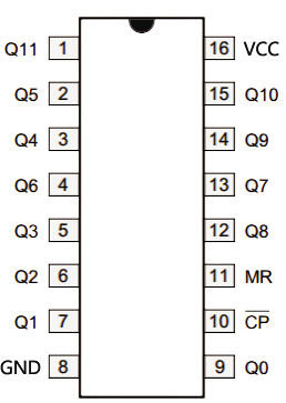
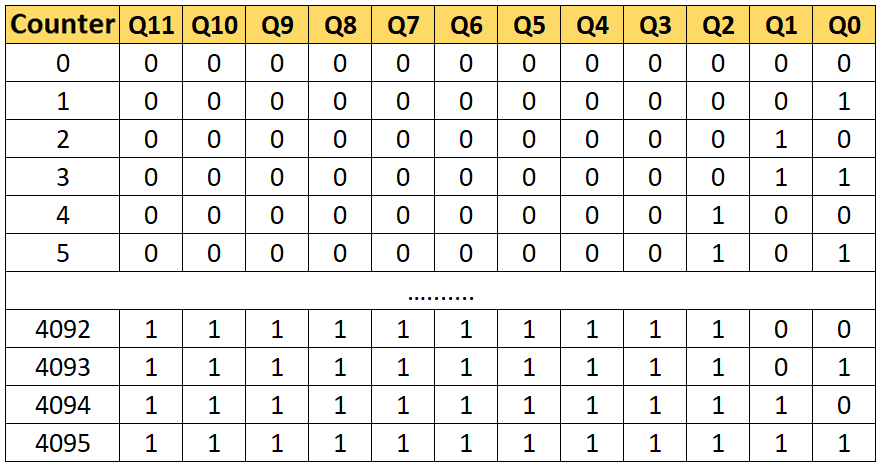
The function is very simple. A switch from HIGH to LOW at CP (Clock Input) increases the counter by 1. A HIGH signal to MR triggers a reset and the counter will be zero again. Depending on the current count reading, the outputs Q0 to Q11 are switched as follows:
Counting pushbutton clicks with an IC 4040
To warm-up, I first present a simple circuit where the counter is incremented by pushbutton. Due to the many LED connections, the circuit is a bit confusing, but actually it is quite simple. The signals for counting or reset are read in via buttons on the Arduino pins 7 and 8. Pins 12 and 13 are connected to CP or MR.
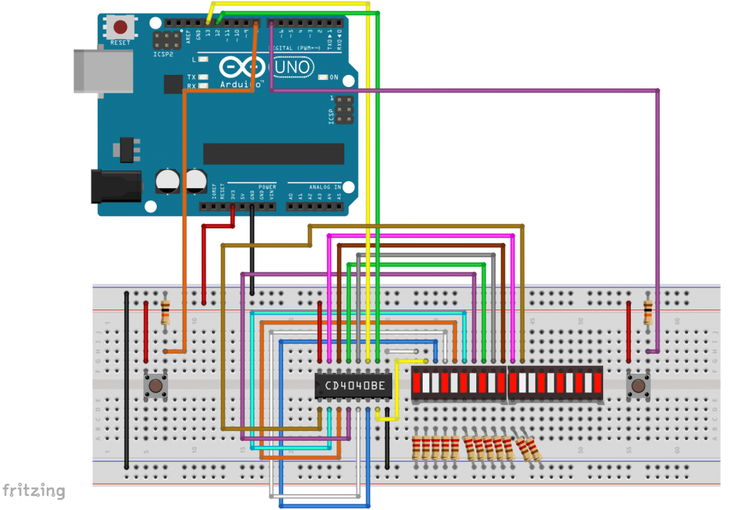
The sketch for this does not have to be explained in detail. The delay(300); instructions are used for debouncing. Have fun counting up to 4095…
int countTasterPin=7;
int resetTasterPin=8;
int resetPin=12;
int clockInput=13;


void setup() {
  pinMode(countTasterPin, INPUT);
  pinMode(resetTasterPin,INPUT);
  pinMode(resetPin,OUTPUT);
  pinMode(clockInput, OUTPUT);
}

void loop() {
  if(digitalRead(resetTasterPin)){
    digitalWrite(resetPin, HIGH);
    digitalWrite(resetPin, LOW);
    delay(300);
  }
  if(digitalRead(countTasterPin)){
    digitalWrite(clockInput,HIGH);
    digitalWrite(clockInput,LOW);
    delay(300);
  }
}
Incrementing the IC 4040 by sketch
If you don’t use buttons and set the counter by sketch, it looks like this:
int clockInput=12;
int resetPin=13;

void setup() {
  pinMode(resetPin,OUTPUT);
  pinMode(clockInput, OUTPUT);
  Serial.begin(9600);
  digitalWrite(resetPin,HIGH);
  digitalWrite(resetPin,LOW);
  delay(1000);
  for(int i=0; i<42; i++){
    digitalWrite(clockInput, HIGH);
    digitalWrite(clockInput, LOW);
  }
  delay(2000);
  digitalWrite(resetPin,HIGH);
  digitalWrite(resetPin,LOW);
  delay(1000);
  for(int i=0; i<2835; i++){
    digitalWrite(clockInput, HIGH);
    digitalWrite(clockInput, LOW);
  }
}

void loop() {
}
Use the IC 4040 for port expansion
You can also use the IC 4040 for port expansion. I tried this on an ESP8266 ESP-01 module. I have explained “real” port extensions here. But why do I say “real”? Is that wrong here? Since you can’t skip a number when counting up, of course there are also outputs that you actually want to be LOW are switched on and off many times until the final count is reached. With the rather sluggish LEDs, this is not so important, in other applications it may be disturbing, if not unacceptable. In this respect, I would call this method a ‘quasi-port expansion’.
Circuit for port expansion of the ESP-01
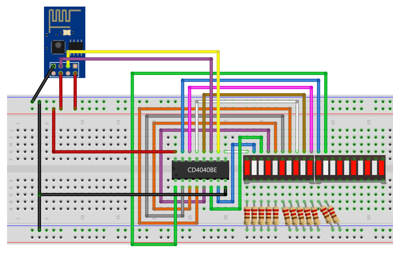
GPIO0 and GPIO2 of the ESP-01 module are used as clock input or reset encoders. How to program an ESP-01 module, I have described here. The rest is not new.
Sketch for port expansion of the ESP-01
This sketch is not very complex either. The LEDs 0 to 11 are defined. Their status is stored in the variable “ledStatus”. The “switchLED” function changes the status according to the passed parameters. Then a reset is performed and the counter increments up to the value of ledStatus.
When switching the upper LEDs, you can see a short glow of the lower LEDs. When the LED 11 is switched on, the LED 0 goes on and off 1024 times. This undesirable, short luminous effect can be significantly reduced by directly accessing the ports of the ESP-01 instead of using the slow digitalWrite() commands. This works slightly differently compared to the Arduino ports: GPOS = (1 << 0);, switches GPIO0 to HIGH, GPOC = (1<<0); switches GPIO0 to LOW. Just try it out.
<div class="scroll-paragraph-long"><pre class="EnlighterJSRAW" data-enlighter-title="esp01_4040_portexpansion.ino" data-enlighter-group="esp01_4040_portexpansion.ino">#define LED0 0
#define LED1 1
#define LED2 2
#define LED3 3
#define LED4 4
#define LED5 5
#define LED6 6
#define LED7 7
#define LED8 8
#define LED9 9
#define LED10 10
#define LED11 11
int clockInput=0;
int resetPin=2;
word ledStatus = 0;

void setup() {
  pinMode(resetPin,OUTPUT);
  pinMode(clockInput, OUTPUT);
  reset4040();
  delay(1000);

  for(int i=0; i<=11; i++){
    switchLED(i,1);
    delay(200);
  }
  delay(1000);
  for(int i=11; i>=0; i--){
    switchLED(i,0);
    delay(200);
  }
  delay(1000);
  switchLED(LED0,1);
  delay(1000);
  switchLED(LED11,1);
  delay(1000);
  switchLED(LED4,1);
  delay(1000);
  switchLED(LED5,1);
  delay(1000);
  switchLED(LED0,0);
  delay(1000);
  switchLED(LED11,0);
  delay(1000);
  switchLED(LED4,0);
  switchLED(LED5,0);
}

void loop() {
  switchLED(LED11,1);
  delay(1000);
  switchLED(LED11,0);
  delay(500);
}

void reset4040(){
  digitalWrite(resetPin,HIGH);
  digitalWrite(resetPin,LOW);
}

void switchLED(word num, bool ledon){
  if(ledon){
    ledStatus |= (1<<num);
  }
  else{
    ledStatus &= ~(1<<num);
  }
  reset4040();
  for(int i=0; i<ledStatus; i++){
    //digitalWrite(clockInput, HIGH);
    //digitalWrite(clockInput, LOW);
    GPOS = (1 << 0);
    GPOC = (1 << 0);
  }
}
The IC 4017
The next representative of the Counter ICs I would like to introduce is the IC 4017. This is also available as DIP16 with different names. I used a CD4017BE from Texas Instruments. The recommended range for the power supply is between 3 and 18 volts. A data sheet is available here.
The big difference to the IC 4040 is that the IC 4017 is a decade counter that counts from zero to nine. Of its 10 output pins, only one is HIGH at a time:
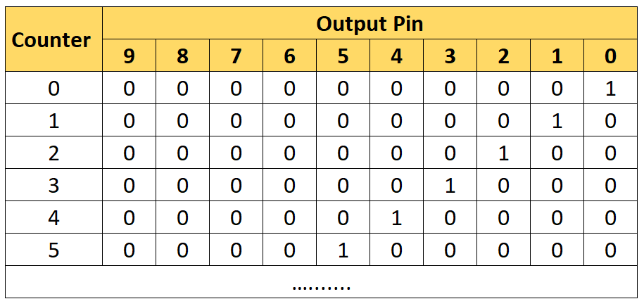
Outputs of the IC 4017 depending on the count; 0 = LOW, 1 = HIGH
It is also worth noting that the output 0 is HIGH in the initial state. This has to be the case, because the IC 4017 is designed to be able to connect several of them in series in order to be able to count up to 100, 1000, 10000, etc. If there was no 0 after the 9, you couldn’t form a 10.
Finally, it should be mentioned that the IC 4017 increments the count when CP changes from LOW to HIGH.
Pinout

In addition to the output pins 0 to 9 and the power supply, the IC 4017 has the following pins:
- MR: reset pin, active-high
- CP: clock input
- CE: clock enable, active-low
- TC: carry through
TC can be connected to the clock pin of another IC 4017. If the count of the first IC 4017 exceeds there is a signal to the following IC 4017 and the output pin 0 of the first IC 4017 will be HIGH.
Multiplexing with the IC 4017
In addition to the actual task, which is counting, the IC 4017 can also be used for multiplexing. Here, as with the IC 4040, the restriction applies again, that when counting, you also switch outputs to HIGH for short time, which you actually want to be LOW. Here, however, unless you switch several IC 4017 in a row, each output on the way to the “target output” only goes up and down briefly only once, which is not visible when controlling LEDs (I hope this is somehow understandable).
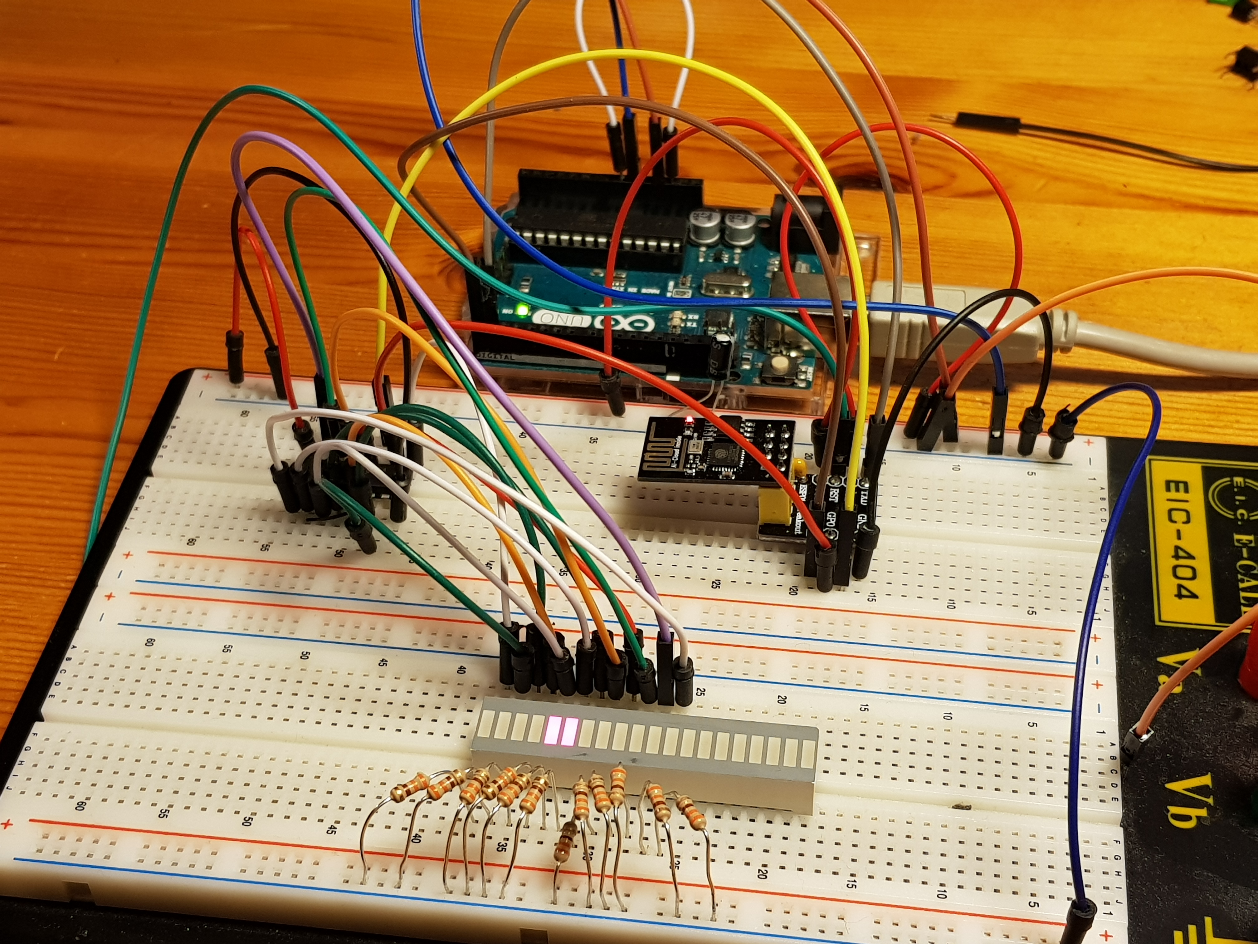
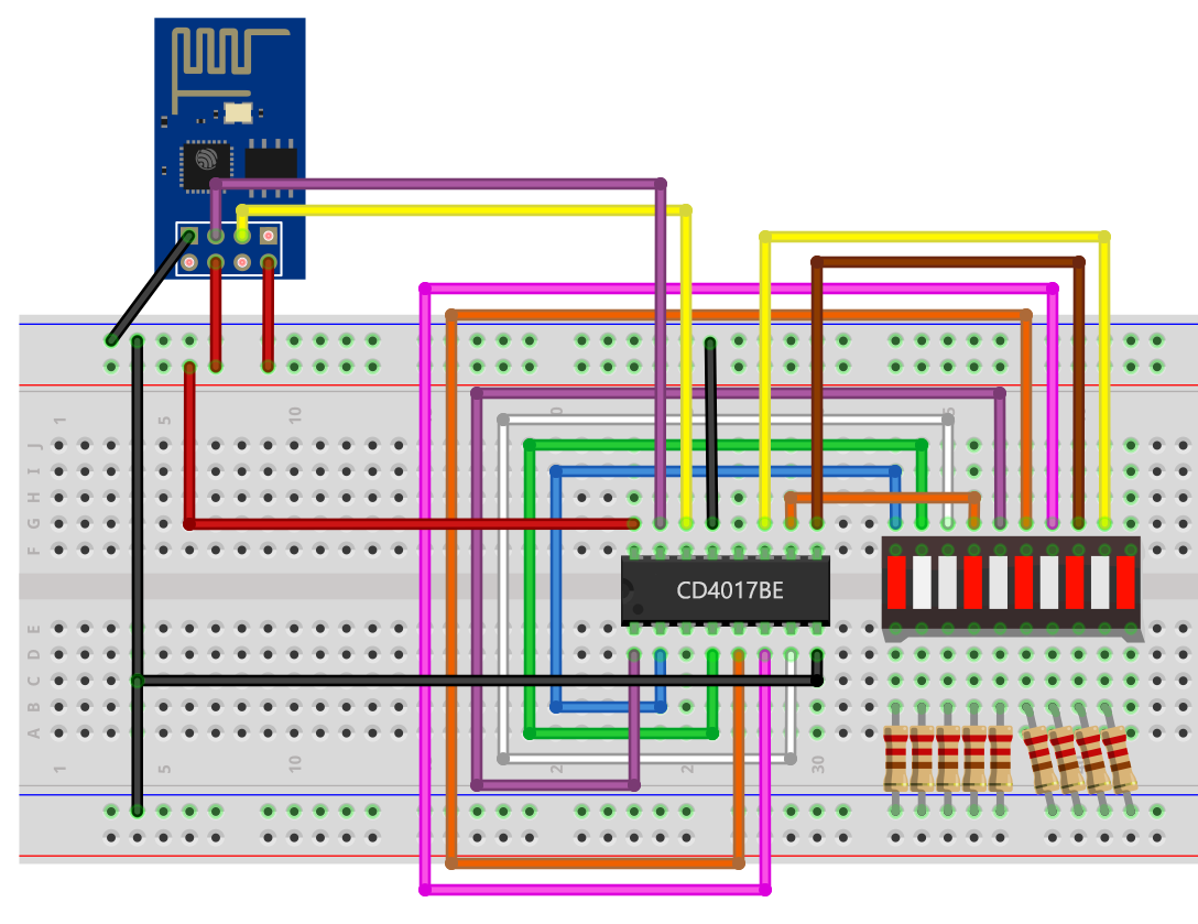
Circuit for multiplexing using the ESP-01
The circuit is simple:
- GPIO0 and GPIO2 control the clock input and the reset
- CE is attached to GND
- TC is not connected because only a single IC 4017 is used here
- I did not connect the output 0 for this purpose, as it is already HIGH when switching on.
One could come up with the idea to take TC as tenth output – but it is also HIGH at the start, switches to LOW at count 6 and then to HIGH again after 9.
The sketch for multiplexing with an ESP-01
The sketch should be self-explanatory:
#define LED1 1
#define LED2 2
#define LED3 3
#define LED4 4
#define LED5 5
#define LED6 6
#define LED7 7
#define LED8 8
#define LED9 9

int clockInput=0;
int resetPin=2;
word ledStatus = 0;

void setup() {
  pinMode(resetPin,OUTPUT);
  pinMode(clockInput, OUTPUT);
  reset4017();
  delay(2000);

  for(int i=1; i<=9; i++){
    digitalWrite(clockInput, HIGH);
    digitalWrite(clockInput, LOW);
    delay(1000);
  }
  delay(1000);
  switchOnLED(LED1);
  delay(1000);
  switchOnLED(LED3);
  delay(1000);
  switchOnLED(LED5);
  delay(1000);
  switchOnLED(LED7);
  delay(1000);
  switchOnLED(LED9);
  delay(1000);
}

void loop() {
}

void reset4017(){
  digitalWrite(resetPin,HIGH);
  digitalWrite(resetPin,LOW);
}

void switchOnLED(byte num){
  reset4017();
  for(byte i=0; i<num; i++){
    digitalWrite(clockInput, HIGH);
    digitalWrite(clockInput, LOW);
  }
}
The IC 4033
And now to the last representative of the Counter ICs, which I would like to introduce here, the IC 4033. It is also available from different manufacturers with different names, but all DIP16 variants I have dealt with had the same pinout. I used the CD4033BE for this post. For example, a data sheet can be found here. The recommended voltage range is between 3 and 18 volts. The IC 4033 is again fundamentally different from the other counter ICs 4017 and 4040, as it is specially designed for controlling 7-segment displays. The IC 4033 counts decadicly and the count is automatically displayed as a digit by activating the corresponding outputs a – g (see diagram) on a 7-segment display.

Pinout

The IC 4033 has the following inputs/outputs:
- VSS / VDD: power supply
- Clock: input for the counting signals
- Clock Inhibit: active-high blocking of the counting function
- a to g: outputs for the individual segments (see diagram)
- Reset: active-high reset
- Carry Out: is connected to Clock of the counter of the next higher digit
- Lamp Test: if connected to HIGH, the count is ignored and all outputs a to g go HIGH
- Ripple Blanking In (RBI) / Ripple Blanking Out (RBO): this controls whether redundant zeros are displayed or not.
The last point needs further explanation. For example, if you have six 7-segment displays and represent “5607”, the display will show “005607” without any further precautions. To get rid of the preceding zeros, the RBI of IC 4033 is connected at the highest digit (most significant digit), i.e. here the hundreds of thousands digit with LOW. RBO of this IC 4033 is connected to the RBI of IC 4033 of the next lower digit, i.e. here the tens of thousands. RBO of this IC 4033 is then connected to the RBI of the next lower digit, etc. In this configuration, the display of the one-digit also remains dark when the number 0 is represented. If you want to prevent this, you stop cascading at the tens and connect RBI of the IC 4033 for the numbers 0-9 with HIGH.
To suppress redundant zeros for the digits behind the comma (or point in American notation) in floats, one proceeds in principle the same way, only that one starts with the procedure at the least significant digit.
According to the count, the outputs are activated so that the correct number is automatically displayed. It’s as simple as it is convenient. Since the activated outputs are “HIGH”, you need 7-segment displays with a common cathode.
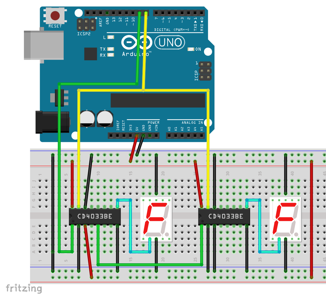
Example circuit for two 7-segment displays
As an example, I show a circuit for two 7-segment displays, which are controlled with an Arduino via the IC 4033. I used SC39-11GWA displays from Kingbright. So that it doesn’t get too confusing, I have drawn only one segment line (“d”). In the photo below you can see the setup with three 7-segment displays.
- Arduino pin 9 is connected to the clock input of the IC 4033 displaying the lowest digit.
- Arduino pin 8 provides the reset signal and is connected to Reset of all the IC 4033
- Lamp Test is hooked up to GND
- Clock Inhibit is connected to GND
- In this simple case, RBI of the IC 4033 for the lower digit is connected to HIGH RBI of the other IC 4033 is connected to LOW.
But where are the resistors in the lines to the 7-segment displays? The IC 4033 supplies only a limited current – it was not necessary to use resistors. Whether you need resistors or not depends on your supply voltage and the 7-segment displays used.

An example sketch
This simple sketch increments the display from 0 to 99. The function displayNumber();, which I do not use here, displays a certain number.
int resetPin=8;
int clockInput=9;

void setup() {
  pinMode(resetPin,OUTPUT);
  pinMode(clockInput, OUTPUT);
  reset4033();
  delay(2000);
}

void loop() {
  for(int i=1; i<=99; i++){
    digitalWrite(clockInput, HIGH);
    digitalWrite(clockInput, LOW);
    delay(500);
  }
  reset4033();
  delay(2000);
}

void reset4033(){
  digitalWrite(resetPin,HIGH);
  digitalWrite(resetPin,LOW);
}

void displayNumber(byte num){
  reset4033();
  for(byte i=0; i<num; i++){
    digitalWrite(clockInput, HIGH);
    digitalWrite(clockInput, LOW);
  }
}