About this Post
In the last post I had reported about programming ATtinys with ATTinyCore. This package allows using the USI interface of the ATtinys for I2C use with the Wire library. Special libraries for the I2C implementation, such as TinyWireM, TinyI2C or USIWire are thus no longer needed. However, since they are leaner, their use on the ATtinys with their limited program memory can still be useful.
In this article, I use Adafruit’s TinyWireM library as an example to explore how big the savings are compared to Wire. I also introduce TinyWireM compatible libraries for some I2C based devices. And finally, I show with two examples that you can modify many I2C based libraries to make them compatible with TinyWireM without much effort.
TinyWireM and TinyWireS
The”M” in TinyWireM stands for Master. That means the library allows to make the ATtiny the I2C master, but not the slave. For the latter, there are several other libraries like TinyWireS. For example, if you wanted two ATtinys to communicate with each other via I2C, you would need both variants. I will confine myself here to the use of the ATtinys as masters in this post.
Preparations and requirements
I assume that you have installed the ATTinyCore package from Spence Konde. I also assume you know how to burn bootloaders and upload sketches with it. If that’s not the case, just check out my last post, where I explained it all in detail.
You should as well have TinyWireM installed. You can get the library via the library manager of the Arduino IDE. Alternatively, you can download the library directly from GitHub here.
For this article, I use an ATtiny85. You can just as well take another ATtiny which is compatible with ATTinyCore. However, it should be a model with 8 kByte program memory. Otherwise, it will be too small for some examples.

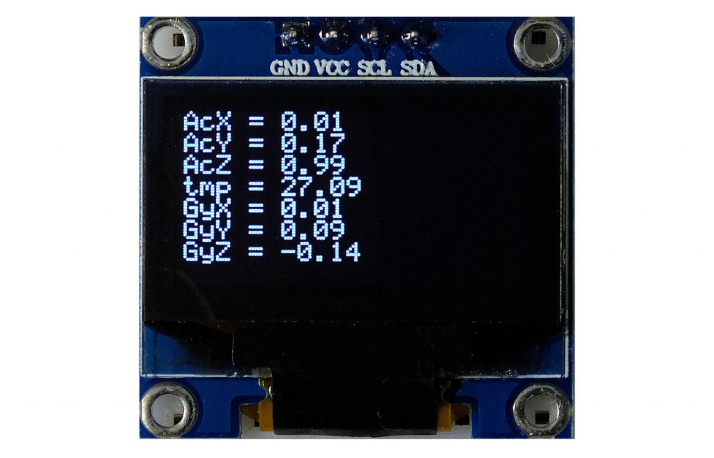
Using TinyWireM and Wire for the MPU6050
In most cases you probably use libraries for I2C devices which do it for you to address the devices on register level using the wire functions. However, to understand the differences between TinyWireM and Wire, let’s now look at an example where we don’t use a component library.
I have chosen the 6-axis gyroscope and accelerometer module MPU6050 as a demonstration object. Those interested in the details of this component can read my post on it. Here and now, it’s all about seeing TinyWireM and Wire in action.
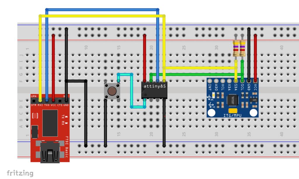
Since I want to output the readings of the MPU6050 on the serial monitor, I burned the Optiboot bootloader to the ATtiny85 and uploaded the sketches with a USB-to-TTL Serial Adapter. The following circuit was used:
MPU6050 Control with Wire
The following sketch uses the wire library for I2C communication. The MPU6050 is “woken up” in the setup. The three acceleration values, the temperature and the three gyroscope values are then read out one after the other in the main loop. Since these are 16-bit values, two registers must be read at a time, for a total of fourteen. Then the values are output on the serial monitor.
#include<Wire.h>
#define MPU6050_ADDR 0x68

int16_t AcX,AcY,AcZ,Tmp,GyX,GyY,GyZ;
void setup(){
  Wire.begin();
  Wire.beginTransmission(MPU6050_ADDR);
  Wire.write(0x6B);  // PWR_MGMT_1 register
  Wire.write(0);     // set to zero (wakes up the MPU6050)
  Wire.endTransmission(true);
  Serial.begin(9600);
}
void loop(){
  Wire.beginTransmission(MPU6050_ADDR);
  Wire.write(0x3B);  // starting with register 0x3B (ACCEL_XOUT_H)
  Wire.endTransmission(false);
  Wire.requestFrom(MPU6050_ADDR,14,true);  // request a total of 14 registers
  AcX=Wire.read()<<8|Wire.read();  // 0x3B (ACCEL_XOUT_H) & 0x3C (ACCEL_XOUT_L)
  AcY=Wire.read()<<8|Wire.read();  // 0x3D (ACCEL_YOUT_H) & 0x3E (ACCEL_YOUT_L)
  AcZ=Wire.read()<<8|Wire.read();  // 0x3F (ACCEL_ZOUT_H) & 0x40 (ACCEL_ZOUT_L)
  Tmp=Wire.read()<<8|Wire.read();  // 0x41 (TEMP_OUT_H) & 0x42 (TEMP_OUT_L)
  GyX=Wire.read()<<8|Wire.read();  // 0x43 (GYRO_XOUT_H) & 0x44 (GYRO_XOUT_L)
  GyY=Wire.read()<<8|Wire.read();  // 0x45 (GYRO_YOUT_H) & 0x46 (GYRO_YOUT_L)
  GyZ=Wire.read()<<8|Wire.read();  // 0x47 (GYRO_ZOUT_H) & 0x48 (GYRO_ZOUT_L)
  delay(2000);
  Serial.println();
  Serial.print(F("AcX = ")); Serial.print(AcX);
  Serial.print(F(" | AcY = ")); Serial.print(AcY);
  Serial.print(F(" | AcZ = ")); Serial.print(AcZ);
  Serial.print(F(" | Tmp = ")); Serial.print(Tmp/340.00+36.53);  //equation for temperature in degrees C from datasheet
  Serial.print(F(" | GyX = ")); Serial.print(GyX);
  Serial.print(F(" | GyY = ")); Serial.print(GyY);
  Serial.print(F(" | GyZ = ")); Serial.println(GyZ);
}
The sketch requires 4058 bytes. This is ~53% of the available program memory (7616 bytes). Reminder: Actually, 8192 bytes are available, but the Optiboot bootloader needs 576 bytes.

For completeness, here is the output:
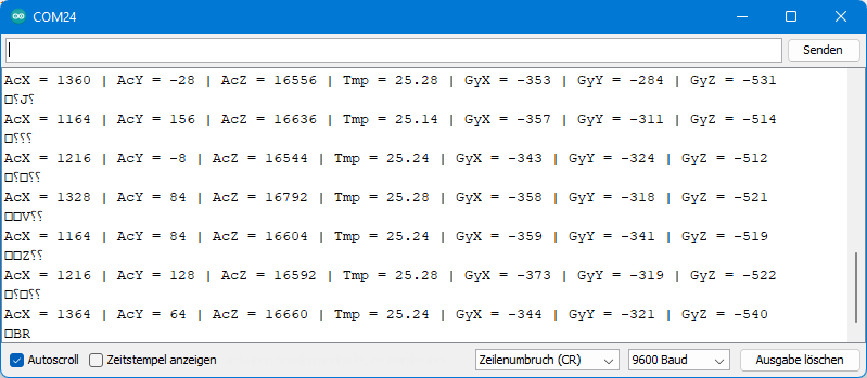
By the way, the ugly special characters come from the fact that pin PB0 is both SDA connector and serial output to the adapter. If this bothers you, you can also do the output via SoftwareSerial, for example with the pins PB3 and PB4. However, you then have to rewire after uploading and use more program memory (4898 bytes in total).
MPU6050 Control with TinyWireM
Even though TinyWireM is internally very different from Wire, the usage is comparable. However, some TinyWireM functions have different names:

Here is the “translation” of the sketch for TinyWireM:
#include <TinyWireM.h>
#define MPU6050_ADDR 0x68

int16_t AcX,AcY,AcZ,Tmp,GyX,GyY,GyZ;
void setup(){
  TinyWireM.begin();
  TinyWireM.beginTransmission(MPU6050_ADDR);
  TinyWireM.send(0x6B);  // PWR_MGMT_1 register
  TinyWireM.send(0);     // set to zero (wakes up the MPU-6050)
  TinyWireM.endTransmission(true);
  Serial.begin(9600);
}
void loop(){
  TinyWireM.beginTransmission(MPU6050_ADDR);
  TinyWireM.send(0x3B);  // starting with register 0x3B (ACCEL_XOUT_H)
  TinyWireM.endTransmission(false);
  TinyWireM.requestFrom(MPU6050_ADDR,14);  // request a total of 14 registers
  AcX=TinyWireM.receive()<<8|TinyWireM.receive();  // 0x3B (ACCEL_XOUT_H) & 0x3C (ACCEL_XOUT_L)
  AcY=TinyWireM.receive()<<8|TinyWireM.receive();  // 0x3D (ACCEL_YOUT_H) & 0x3E (ACCEL_YOUT_L)
  AcZ=TinyWireM.receive()<<8|TinyWireM.receive();  // 0x3F (ACCEL_ZOUT_H) & 0x40 (ACCEL_ZOUT_L)
  Tmp=TinyWireM.receive()<<8|TinyWireM.receive();  // 0x41 (TEMP_OUT_H) & 0x42 (TEMP_OUT_L)
  GyX=TinyWireM.receive()<<8|TinyWireM.receive();  // 0x43 (GYRO_XOUT_H) & 0x44 (GYRO_XOUT_L)
  GyY=TinyWireM.receive()<<8|TinyWireM.receive();  // 0x45 (GYRO_YOUT_H) & 0x46 (GYRO_YOUT_L)
  GyZ=TinyWireM.receive()<<8|TinyWireM.receive();  // 0x47 (GYRO_ZOUT_H) & 0x48 (GYRO_ZOUT_L)
  delay(2000);
  Serial.println();
  Serial.print(F("AcX = ")); Serial.print(AcX);
  Serial.print(F(" | AcY = ")); Serial.print(AcY);
  Serial.print(F(" | AcZ = ")); Serial.print(AcZ);
  Serial.print(F(" | Tmp = ")); Serial.print(Tmp/340.00+36.53);  //equation for temperature in degrees C from datasheet
  Serial.print(F(" | GyX = ")); Serial.print(GyX);
  Serial.print(F(" | GyY = ")); Serial.print(GyY);
  Serial.print(F(" | GyZ = ")); Serial.println(GyZ);
}
This sketch needs only 3538 bytes, which is 520 bytes less. This corresponds to about one sixteenth of the 8 kByte program memory. With an ATtiny45 it would be already one eighth. This may not sound like much, but it could be just the bytes that decide which ATtiny you can use.

TinyWireM compatible libraries
As you have just seen, you can save valuable program memory with TinyWireM. But you have also seen that some function names of TinyWireM and Wire are different. To control an I2C-based component, you cannot simply include TinyWireM.h instead of Wire.h. The library must either be written for TinyWireM or allow its use as an option. I would like to show some examples of this. You can find all libraries I use for the examples on GitHub, or install them via the library manager of the Arduino IDE.
1. OLED display control with Tiny4kOLED
My first example is the library Tiny4kOLED, which is used to control small I2C-based OLED displays. The displays are available with 128 x 64 or 128 x 32 pixels. This is not lush, but sufficient to display a few measured values, for example.
Since we don’t need the serial monitor anymore, I programmed the ATtiny85 via ISP without bootloader in all upcoming examples.
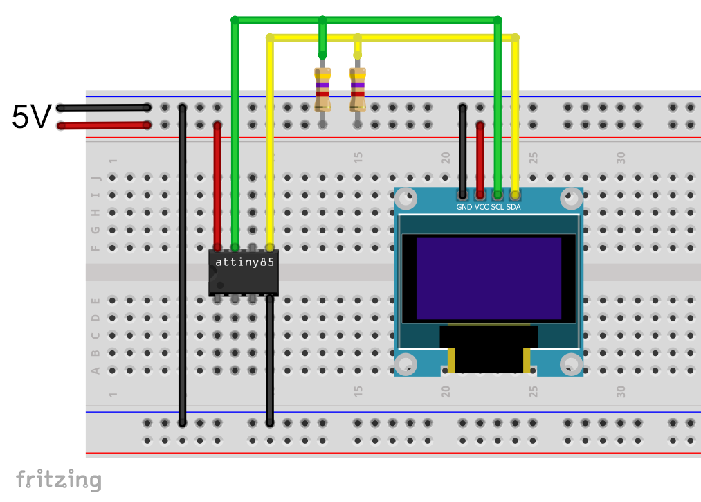
The following circuit was used to operate the display:
I won’t get into the details of the Tiny4kOLED library. There are many good example sketches included. Here is just a small “Hello World” sketch for illustration and as a test:
#include <TinyWireM.h>
#include <Tiny4kOLED.h>

uint8_t width = 128;
uint8_t height = 64;

void setup() {
  TinyWireM.begin();
  oled.begin(width, height, sizeof(tiny4koled_init_128x64br), tiny4koled_init_128x64br);
  oled.clear();
  oled.setFont(FONT6X8);
  oled.on();
  oled.setCursor(30, 4); // x: pixel / y: line
  oled.print("Hello world");
}

void loop() {
}
The sketch requires 2682 bytes, which is ~32% of the program memory.

And this is how the output looks on the display:

For comparison: Control with SSD1306Acii and Wire
For comparison, I tried a lean Wire.h-based library, namely SSD1306Ascii:
#include <Wire.h>
#include "SSD1306Ascii.h"
#include "SSD1306AsciiWire.h"
#define I2C_ADDRESS 0x3C

SSD1306AsciiWire oled;

void setup() {
  Wire.begin();
  oled.begin(&Adafruit128x64, I2C_ADDRESS);
  oled.setFont(System5x7);
  oled.clear();
  oled.setCursor(30,4);
  oled.print("Hello world!");
}

void loop() {}
The difference to the Tiny4kOLED solution was still 442 bytes:
2. control of the MCP23017 Port Expander
Switch between Wire and TinyWireM
I have rewritten three of my libraries to work with both Wire and TinyWireM. For this purpose I added a file named component_config.h (e.g. MCP23017_config.h) to each of the libraries, in which you only have to uncomment the line #define USE_TINY_WIRE_M_ to switch to the TinyWireM library. You can find the config files in the Arduino “libraries” folder → library name → src.
The preprocessor directives #ifdef (if defined), #ifndef (if not defined), #else and #endif control which code is compiled and which is ignored. Here is a snippet:
#ifndef USE_TINY_WIRE_M_
        _wire->beginTransmission(I2C_Address);
        _wire->write(reg);
        _wire->endTransmission(false);
        _wire->requestFrom(I2C_Address, 1);
        regVal = _wire->read();
#else
        TinyWireM.beginTransmission(I2C_Address);
        TinyWireM.send(reg);
        TinyWireM.endTransmission();
        TinyWireM.requestFrom(I2C_Address, 1);
        regVal = TinyWireM.receive();
#endif
Just don’t forget to comment out #define USE_TINY_WIRE_M_ again when you change the microcontroller and want to change back to Wire.
By the way, I had initially tried to simply write #define USE_TINY_WIRE_M_ into the sketch. In the process I learned that the preprocessor does not proceed line by line when reading the sketch, but apparently reads the include files first. As a result, USE_TINY_WIRE_M_ was initially undefined, which led to corresponding error messages. Hence, the cumbersome solution with the configuration file.
And now for the library MCP23017_WE
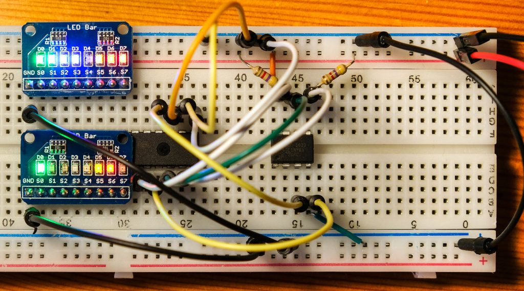
The library MCP23017_WE controls the MCP23017 port expander, which provides you with additional 16 GPIOs. For details, check out my post on this component. For testing the control via ATtiny85 (in principle) the following circuit was used:
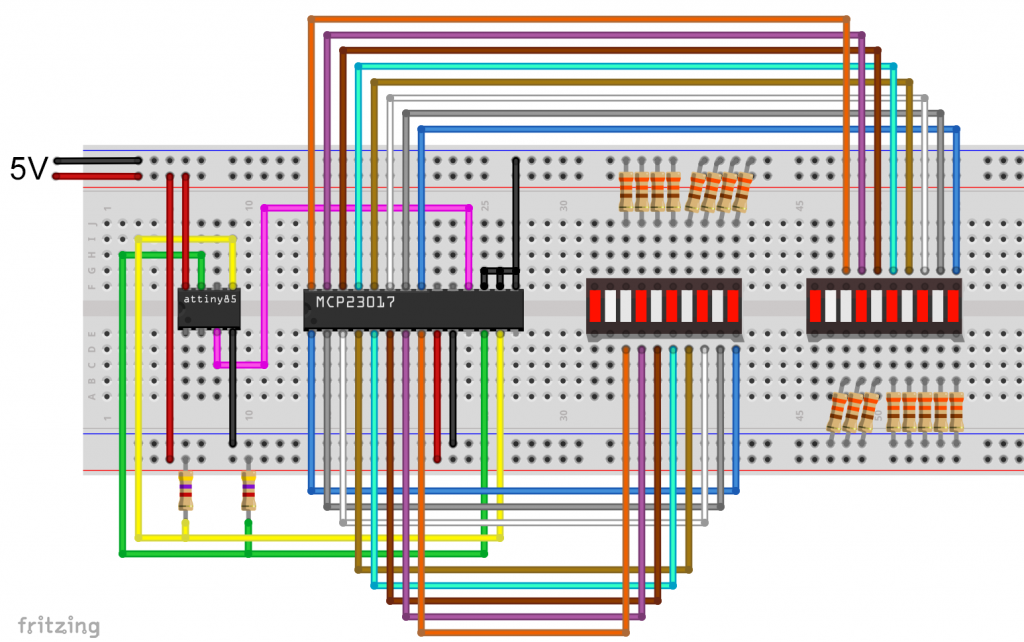
Being convenient, I used LED bars with common cathode and integrated resistors:
And here is the example sketch:
#include <TinyWireM.h>
#include <MCP23017_WE.h>
#define MCP_ADDRESS 0x20 // (A2/A1/A0 = LOW)
#define RESET_PIN 4

typedef MCP23017_WE MCP;
MCP myMCP = MCP(MCP_ADDRESS, RESET_PIN);

int wT = 1000; // wT = waiting time

void setup(){
  TinyWireM.begin();
  myMCP.Init();
  myMCP.setPortMode(0b11111101, MCP::A);  // Port A: all pins are OUTPUT except pin 1
  myMCP.setPortMode(0b11111111, MCP::B);  // Port B: all pins are OUTPUT
  delay(wT);
  myMCP.setAllPins(MCP::A, MCP::ON); // alle LEDs switched on except A1
  delay(wT);
  myMCP.setPinX(1, MCP::A, OUTPUT, HIGH); // A1 switched on
  delay(wT);
  myMCP.setPort(0b11110000, MCP::B); // B4 - B7 switched on
  delay(wT);
  myMCP.setPort(0b01011110, MCP::A); // A0,A5,A7 switched off
  delay(wT);
  myMCP.setPinX(0, MCP::B, OUTPUT, HIGH); // B0 switched on
  delay(wT);
  myMCP.setPinX(4, MCP::B, OUTPUT, LOW); // B4 switched off
  delay(wT);
  myMCP.setAllPins(MCP::A, HIGH); // A0 - A7 all on
  delay(wT);
  myMCP.setPin(3, MCP::A, LOW); // A3 switched off
  delay(wT);
  myMCP.setPortX(0b11110000, 0b01101111, MCP::B); // at port B only B5,B6 are switched on
  delay(wT);
  myMCP.setPinMode(0, MCP::B, OUTPUT); // B0 --> OUTPUT
  for(int i=0; i<5; i++){  // B0 blinking
    myMCP.togglePin(0, MCP::B);
    delay(200);
    myMCP.togglePin(0, MCP::B);
    delay(200);
  }
  for(int i=0; i<5; i++){ // B7 blinking
    myMCP.togglePin(7, MCP::B);
    delay(200);
    myMCP.togglePin(7, MCP::B);
    delay(200);
  }
}

void loop(){
}
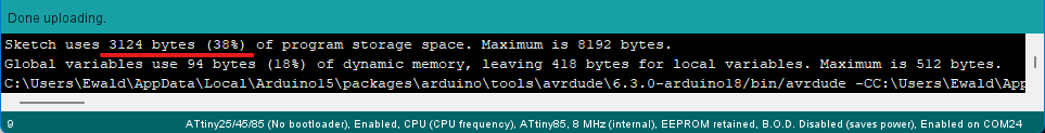
The memory requirement of the sketch is 2106 bytes, which is about 25 percent.
3. Controlling the INA219 current sensor
The library INA219_WE is used to controlling the current sensor INA219, which I have reported about in detail here.
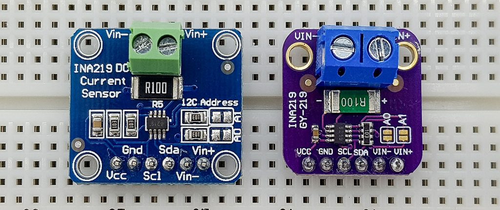
This is the circuit that was used:
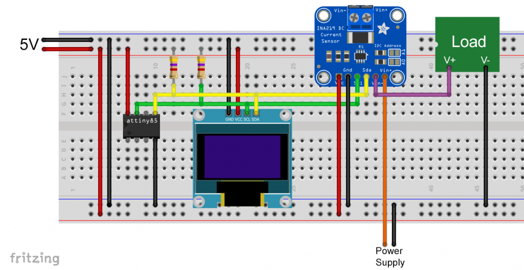
The component “Load” stands for any consumer.
And here is the example sketch, which needs 72 percent of the program memory of the ATtiny85:
#include <TinyWireM.h>
#include <Tiny4kOLED.h>
#include <INA219_WE.h>
#define I2C_ADDRESS 0x40

uint8_t width = 128;
uint8_t height = 64;

/* There are several ways to create your INA219 object:
 * INA219_WE ina219 = INA219_WE()              -> uses I2C Address = 0x40
 * INA219_WE ina219 = INA219_WE(ICM20948_ADDR) -> define I2C_ADDRESS
 */
INA219_WE ina219 = INA219_WE(I2C_ADDRESS);

void setup() {
  TinyWireM.begin();
  oled.begin(width, height, sizeof(tiny4koled_init_128x64br), tiny4koled_init_128x64br);
  oled.setFont(FONT6X8);
  oled.clear();
  oled.on();

  oled.setCursor(0, 0);
  if(!ina219.init()){
     oled.print("INA219 not connected!");
     while(1){}
  }
  else{
    oled.print("INA219 connected");
    delay(1000);
    oled.clear();
  }

  /* Set ADC Mode for Bus and ShuntVoltage
  * Mode *            * Res / Samples *       * Conversion Time *
  BIT_MODE_9        9 Bit Resolution             84 µs
  BIT_MODE_10       10 Bit Resolution            148 µs
  BIT_MODE_11       11 Bit Resolution            276 µs
  BIT_MODE_12       12 Bit Resolution            532 µs  (DEFAULT)
  SAMPLE_MODE_2     Mean Value 2 samples         1.06 ms
  SAMPLE_MODE_4     Mean Value 4 samples         2.13 ms
  SAMPLE_MODE_8     Mean Value 8 samples         4.26 ms
  SAMPLE_MODE_16    Mean Value 16 samples        8.51 ms
  SAMPLE_MODE_32    Mean Value 32 samples        17.02 ms
  SAMPLE_MODE_64    Mean Value 64 samples        34.05 ms
  SAMPLE_MODE_128   Mean Value 128 samples       68.10 ms
  */
  //ina219.setADCMode(SAMPLE_MODE_128); // choose mode and uncomment for change of default

  /* Set measure mode
  POWER_DOWN - INA219 switched off
  TRIGGERED  - measurement on demand
  ADC_OFF    - Analog/Digital Converter switched off
  CONTINUOUS  - Continuous measurements (DEFAULT)
  */
  // ina219.setMeasureMode(CONTINUOUS); // choose mode and uncomment for change of default

  /* Set PGain
  * Gain *  * Shunt Voltage Range *   * Max Current (if shunt is 0.1 ohms) *
   PG_40       40 mV                    0.4 A
   PG_80       80 mV                    0.8 A
   PG_160      160 mV                   1.6 A
   PG_320      320 mV                   3.2 A (DEFAULT)
  */
  // ina219.setPGain(PG_320); // choose gain and uncomment for change of default

  /* Set Bus Voltage Range
   BRNG_16   -> 16 V
   BRNG_32   -> 32 V (DEFAULT)
  */
  // ina219.setBusRange(BRNG_32); // choose range and uncomment for change of default

  /* If the current values delivered by the INA219 differ by a constant factor
     from values obtained with calibrated equipment you can define a correction factor.
     Correction factor = current delivered from calibrated equipment / current delivered by INA219
  */
  // ina219.setCorrectionFactor(0.98); // insert your correction factor if necessary

  /* If you experience a shunt voltage offset, that means you detect a shunt voltage which is not
     zero, although the current should be zero, you can apply a correction. For this, uncomment the
     following function and apply the offset you have detected.
  */
  // ina219.setShuntVoltOffset_mV(0.5); // insert the shunt voltage (millivolts) you detect at zero current
}

void loop() {
  float shuntVoltage_mV = 0.0;
  float loadVoltage_V = 0.0;
  float busVoltage_V = 0.0;
  float current_mA = 0.0;
  float power_mW = 0.0;
  bool ina219_overflow = false;

  shuntVoltage_mV = ina219.getShuntVoltage_mV();
  busVoltage_V = ina219.getBusVoltage_V();
  current_mA = ina219.getCurrent_mA();
  power_mW = ina219.getBusPower();
  //loadVoltage_V  = busVoltage_V + (shuntVoltage_mV/1000);
  //ina219_overflow = ina219.getOverflow();

  oled.setCursor(0,0);
  oled.print("Current [mA]: ");
  oled.print(current_mA);
  oled.clearToEOL();

  oled.setCursor(0,2); //10
  oled.print("Power [mW]:   ");
  oled.print(power_mW);
  oled.clearToEOL();

  oled.setCursor(0,4);
  oled.print("Bus [V]:      ");
  oled.print(busVoltage_V);
  oled.clearToEOL();

  oled.setCursor(0,6);
  oled.print("Shunt [mV]:   ");
  oled.print(shuntVoltage_mV);
  oled.clearToEOL();

  delay(3000);
}
Before you apply the sketch, you have to uncomment the line #define USE_TINY_WIRE_M_ in the file INA219_config.h again.
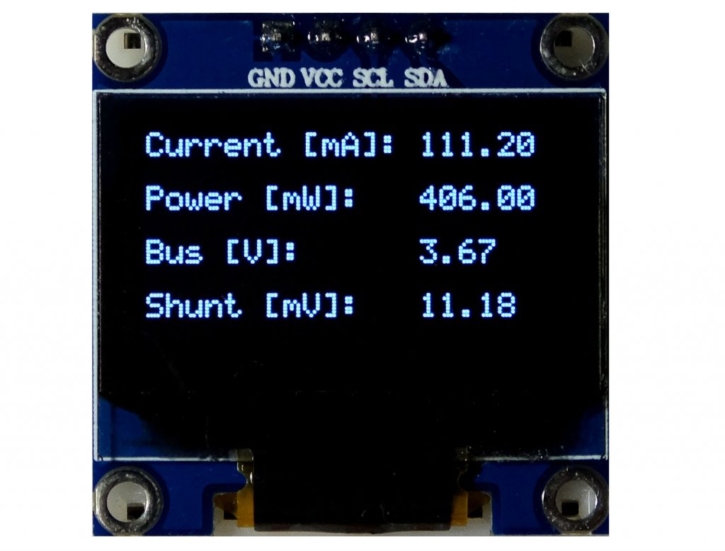
The output looked like this:
4. Controlling the ADS1115 A/D converter
Finally, I customized my ADS1115_WE library, which can be used to control the ADS1115 16-bit, 4-channel A/D converter. I have reported about this nice component here.
The following circuit was used:
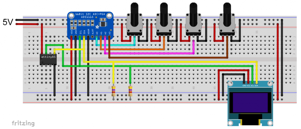
The four potentiometers represent the voltage inputs to be converted.
And that was my test sketch, which took up 73 percent of the program memory:
#include <TinyWireM.h>
#include <Tiny4kOLED.h>
#include<ADS1115_WE.h>
#define ADS1115_I2C_ADDR 0x48
uint8_t width = 128;
uint8_t height = 64;

/* There are two ways to create your ADS1115_WE object:
 * ADS1115_WE adc = ADS1115_WE()             -> uses Wire / I2C Address = 0x48
 * ADS1115_WE adc = ADS1115_WE(I2C_ADDRESS)  -> uses Wire / I2C_ADDRESS
 */
ADS1115_WE adc = ADS1115_WE(ADS1115_I2C_ADDR);

void setup() {
  TinyWireM.begin();
  oled.begin(width, height, sizeof(tiny4koled_init_128x64br), tiny4koled_init_128x64br);
  oled.clear();
  oled.setFont(FONT6X8);
  oled.on();

  if(!adc.init()){
     oled.print("ADS1115 not connected");
     while(1){}
  }
  else{
    oled.print("ADS1115 connected");
    delay(1000);
    oled.clear();
  }

  /* Set the voltage range of the ADC to adjust the gain
   * Please note that you must not apply more than VDD + 0.3V to the input pins!
   *
   * ADS1115_RANGE_6144  ->  +/- 6144 mV
   * ADS1115_RANGE_4096  ->  +/- 4096 mV
   * ADS1115_RANGE_2048  ->  +/- 2048 mV (default)
   * ADS1115_RANGE_1024  ->  +/- 1024 mV
   * ADS1115_RANGE_0512  ->  +/- 512 mV
   * ADS1115_RANGE_0256  ->  +/- 256 mV
   */
  adc.setVoltageRange_mV(ADS1115_RANGE_6144); //comment line/change parameter to change range

  /* Set the inputs to be compared
   *
   *  ADS1115_COMP_0_1    ->  compares 0 with 1 (default)
   *  ADS1115_COMP_0_3    ->  compares 0 with 3
   *  ADS1115_COMP_1_3    ->  compares 1 with 3
   *  ADS1115_COMP_2_3    ->  compares 2 with 3
   *  ADS1115_COMP_0_GND  ->  compares 0 with GND
   *  ADS1115_COMP_1_GND  ->  compares 1 with GND
   *  ADS1115_COMP_2_GND  ->  compares 2 with GND
   *  ADS1115_COMP_3_GND  ->  compares 3 with GND
   */
  adc.setCompareChannels(ADS1115_COMP_0_GND); //comment line/change parameter to change channel

  /* Set number of conversions after which the alert pin asserts
   * - or you can disable the alert
   *
   *  ADS1115_ASSERT_AFTER_1  -> after 1 conversion
   *  ADS1115_ASSERT_AFTER_2  -> after 2 conversions
   *  ADS1115_ASSERT_AFTER_4  -> after 4 conversions
   *  ADS1115_DISABLE_ALERT   -> disable comparator / alert pin (default)
   */
  //adc.setAlertPinMode(ADS1115_ASSERT_AFTER_1); //uncomment if you want to change the default

  /* Set the conversion rate in SPS (samples per second)
   * Options should be self-explaining:
   *
   *  ADS1115_8_SPS
   *  ADS1115_16_SPS
   *  ADS1115_32_SPS
   *  ADS1115_64_SPS
   *  ADS1115_128_SPS (default)
   *  ADS1115_250_SPS
   *  ADS1115_475_SPS
   *  ADS1115_860_SPS
   */
  // adc.setConvRate(ADS1115_8_SPS); //uncomment if you want to change the default

  /* Set continuous or single shot mode:
   *
   *  ADS1115_CONTINUOUS  ->  continuous mode
   *  ADS1115_SINGLE     ->  single shot mode (default)
   */
  adc.setMeasureMode(ADS1115_CONTINUOUS); //comment line/change parameter to change mode

   /* Choose maximum limit or maximum and minimum alert limit (window) in Volt - alert pin will
   *  assert when measured values are beyond the maximum limit or outside the window
   *  Upper limit first: setAlertLimit_V(MODE, maximum, minimum)
   *  In max limit mode the minimum value is the limit where the alert pin assertion will be
   *  cleared (if not latched)
   *
   *  ADS1115_MAX_LIMIT
   *  ADS1115_WINDOW
   *
   */
  //adc.setAlertModeAndLimit_V(ADS1115_MAX_LIMIT, 3.0, 1.5); //uncomment if you want to change the default

  /* Enable or disable latch. If latch is enabled the alert pin will assert until the
   * conversion register is read (getResult functions). If disabled the alert pin assertion will be
   * cleared with next value within limits.
   *
   *  ADS1115_LATCH_DISABLED (default)
   *  ADS1115_LATCH_ENABLED
   */
  //adc.setAlertLatch(ADS1115_LATCH_ENABLED); //uncomment if you want to change the default

  /* Sets the alert pin polarity if active:
   *
   * ADS1115_ACT_LOW  ->  active low (default)
   * ADS1115_ACT_HIGH ->  active high
   */
  //adc.setAlertPol(ADS1115_ACT_LOW); //uncomment if you want to change the default

  /* With this function the alert pin will assert, when a conversion is ready.
   * In order to deactivate, use the setAlertLimit_V function
   */
  //adc.setAlertPinToConversionReady(); //uncomment if you want to change the default
}

  /* If you change the compare channels you can immediately read values from the conversion
   * register, although they might belong to the former channel if no precautions are taken.
   * It takes about the time needed for two conversions to get the correct data. In single
   * shot mode you can use the isBusy() function to wait for data from the new channel. This
   * does not work in continuous mode.
   * To solve this issue the library adds a delay after change of channels if you are in contunuous
   * mode. The length of the delay is adjusted to the conversion rate. But be aware that the output
   * rate will be much lower that the conversion rate if you change channels frequently.
   */

void loop() {
  float voltage = 0.0;

  adc.setCompareChannels(ADS1115_COMP_0_GND);
  voltage = adc.getResult_V();
  oled.setCursor(0,0);
  oled.print("Channel 0 [V]: ");
  oled.print(voltage);
  oled.clearToEOL();

  adc.setCompareChannels(ADS1115_COMP_1_GND);
  voltage = adc.getResult_V();
  oled.setCursor(0,2);
  oled.print("Channel 1 [V]: ");
  oled.print(voltage);
  oled.clearToEOL();

  adc.setCompareChannels(ADS1115_COMP_2_GND);
  voltage = adc.getResult_V();
  oled.setCursor(0,4);
  oled.print("Channel 2 [V]: ");
  oled.print(voltage);
  oled.clearToEOL();

  adc.setCompareChannels(ADS1115_COMP_3_GND);
  voltage = adc.getResult_V();
  oled.setCursor(0,6);
  oled.print("Channel 3 [V]: ");
  oled.print(voltage);
  oled.clearToEOL();

  delay(2000);
}
Here is the output on the OLED display:

Making libraries TinyWireM compatible
You want to use TinyWireM, but the library of your I2C device is incompatible with TinyWireM? Then adjust it! I will give two examples of this.
I would like to say in advance that this is not as easy with every library as described here. Some libraries are more complex, so that larger interventions are necessary, others are simply too large and do not fit into the 8 kByte program memory.
And, of course, there is a disadvantage: if the author of the library releases an update, you will have to stay with the old version or adapt the new version again.
I2C with the ATtiny85 – MPU6050
For the first example, I come back to the MPU6050. I have chosen the MPU6050_light library from rfetick as the demonstration object.
The relevant library files are MPU6050_light.h and MPU6050_light.cpp. First, we turn to the header file (“.h”).
But first the link to the license, which must be referred to if you publish the library in whole or in part. And that’s what I’m doing here.
Modifying MPU6050_light.h
For editing, it is best to use a file editor that highlights program code. I recommend the free Notepad++. Use the editor to open the header file and search for “Wire” and “TwoWire”. Wire is an object of the TwoWire class. All lines that contain these words need your attention.
In this case, the wire object is passed to the MPU6050 object as a reference (&w). You can recognize this by the line MPU6050(TwoWire &w);. We change this procedure and work without handover. Sounds complicated? But it is not. Only a few changes are necessary. I marked them with /////// Take out!!!! and with /////// Add !!!!:
#ifndef MPU6050_LIGHT_H
#define MPU6050_LIGHT_H

#include "Arduino.h"
/////// #include "Wire.h" /////// Take out!!!!
#include<TinyWireM.h>  /////// Add!!!!

#define MPU6050_ADDR                  0x68
#define MPU6050_SMPLRT_DIV_REGISTER   0x19
#define MPU6050_CONFIG_REGISTER       0x1a
#define MPU6050_GYRO_CONFIG_REGISTER  0x1b
#define MPU6050_ACCEL_CONFIG_REGISTER 0x1c
#define MPU6050_PWR_MGMT_1_REGISTER   0x6b

#define MPU6050_GYRO_OUT_REGISTER     0x43
#define MPU6050_ACCEL_OUT_REGISTER    0x3B

#define RAD_2_DEG             57.29578 // [deg/rad]
#define CALIB_OFFSET_NB_MES   500
#define TEMP_LSB_2_DEGREE     340.0    // [bit/celsius]
#define TEMP_LSB_OFFSET       12412.0

#define DEFAULT_GYRO_COEFF    0.98

class MPU6050{
  public:
    // INIT and BASIC FUNCTIONS
  /////// MPU6050(TwoWire &w); Take out !!!!
  MPU6050(); /////// Add!!!!
    byte begin(int gyro_config_num=1, int acc_config_num=0);

  byte writeData(byte reg, byte data);
    byte readData(byte reg);

  void calcOffsets(bool is_calc_gyro=true, bool is_calc_acc=true);
  void calcGyroOffsets(){ calcOffsets(true,false); }; // retro-compatibility with v1.0.0
  void calcAccOffsets(){ calcOffsets(false,true); }; // retro-compatibility with v1.0.0

  void setAddress(uint8_t addr){ address = addr; };
  uint8_t getAddress(){ return address; };

  // MPU CONFIG SETTER
  byte setGyroConfig(int config_num);
  byte setAccConfig(int config_num);

    void setGyroOffsets(float x, float y, float z);
  void setAccOffsets(float x, float y, float z);

  void setFilterGyroCoef(float gyro_coeff);
  void setFilterAccCoef(float acc_coeff);

  // MPU CONFIG GETTER
  float getGyroXoffset(){ return gyroXoffset; };
    float getGyroYoffset(){ return gyroYoffset; };
    float getGyroZoffset(){ return gyroZoffset; };

  float getAccXoffset(){ return accXoffset; };
  float getAccYoffset(){ return accYoffset; };
  float getAccZoffset(){ return accZoffset; };

  float getFilterGyroCoef(){ return filterGyroCoef; };
  float getFilterAccCoef(){ return 1.0-filterGyroCoef; };

  // DATA GETTER
    float getTemp(){ return temp; };

    float getAccX(){ return accX; };
    float getAccY(){ return accY; };
    float getAccZ(){ return accZ; };

    float getGyroX(){ return gyroX; };
    float getGyroY(){ return gyroY; };
    float getGyroZ(){ return gyroZ; };

  float getAccAngleX(){ return angleAccX; };
    float getAccAngleY(){ return angleAccY; };

    float getAngleX(){ return angleX; };
    float getAngleY(){ return angleY; };
    float getAngleZ(){ return angleZ; };

  // INLOOP UPDATE
  void fetchData(); // user should better call 'update' that includes 'fetchData'
    void update();

  // UPSIDE DOWN MOUNTING
  bool upsideDownMounting = false;


  private:
    /////// TwoWire *wire;  /////// Take out!!!!
  uint8_t address = MPU6050_ADDR; // 0x68 or 0x69
  float gyro_lsb_to_degsec, acc_lsb_to_g;
    float gyroXoffset, gyroYoffset, gyroZoffset;
  float accXoffset, accYoffset, accZoffset;
    float temp, accX, accY, accZ, gyroX, gyroY, gyroZ;
    float angleAccX, angleAccY;
    float angleX, angleY, angleZ;
    long preInterval;
    float filterGyroCoef; // complementary filter coefficient to balance gyro vs accelero data to get angle
};

#endif
Modifying MPU6050_light.cpp
Then we modify the “.cpp” file. Again, we need to look for “Wire” and “TwoWire”. As already mentioned, Wire is passed as a reference in the original version of the library. The reference is then assigned to the variable wire with wire = &w. Since this is a reference, the arrow operator is used here instead of the point operator, e.g. wire->beginTransmission() instead of the perhaps more familiar Wire.beginTransmission(). We replace all of that with the TinyWireM counterparts.
#include "MPU6050_light.h"
#include "Arduino.h"

/* Wrap an angle in the range [-limit,+limit] (special thanks to Edgar Bonet!) */
static float wrap(float angle,float limit){
  while (angle >  limit) angle -= 2*limit;
  while (angle < -limit) angle += 2*limit;
  return angle;
}

/* INIT and BASIC FUNCTIONS */

/////// MPU6050::MPU6050(TwoWire &w){ ///////Take out!!!!
///////  wire = &w; /////// Take out!!!!
MPU6050::MPU6050(){  /////// Add
  setFilterGyroCoef(DEFAULT_GYRO_COEFF);
  setGyroOffsets(0,0,0);
  setAccOffsets(0,0,0);
}

byte MPU6050::begin(int gyro_config_num, int acc_config_num){
  // changed calling register sequence [https://github.com/rfetick/MPU6050_light/issues/1] -> thanks to augustosc
  byte status = writeData(MPU6050_PWR_MGMT_1_REGISTER, 0x01); // check only the first connection with status
  writeData(MPU6050_SMPLRT_DIV_REGISTER, 0x00);
  writeData(MPU6050_CONFIG_REGISTER, 0x00);
  setGyroConfig(gyro_config_num);
  setAccConfig(acc_config_num);

  this->update();
  angleX = this->getAccAngleX();
  angleY = this->getAccAngleY();
  preInterval = millis(); // may cause lack of angular accuracy if begin() is much before the first update()
  return status;
}

byte MPU6050::writeData(byte reg, byte data){
///////  wire->beginTransmission(address);/////// Take out!!!!
///////  wire->write(reg);/////// Take out!!!!
///////  wire->write(data);/////// Take out!!!!
///////  byte status = wire->endTransmission();/////// Take out!!!!
  TinyWireM.beginTransmission(address);/////// Add
  TinyWireM.send(reg);/////// Add
  TinyWireM.send(data);/////// Add
  byte status = TinyWireM.endTransmission();/////// Add
  return status; // 0 if success
}

// This method is not used internaly, maybe by user...
byte MPU6050::readData(byte reg) {
///////  wire->beginTransmission(address);/////// Take out!!!!
///////  wire->write(reg);/////// Take out!!!!
///////  wire->endTransmission(true);/////// Take out!!!!
///////  wire->requestFrom(address,(uint8_t) 1);/////// Take out!!!!
///////  byte data =  wire->read();/////// Take out!!!!
  TinyWireM.beginTransmission(address);/////// Add
  TinyWireM.send(reg);/////// Add
  TinyWireM.endTransmission(true);/////// Add
  TinyWireM.requestFrom(address,(uint8_t) 1);/////// Add
  byte data =  TinyWireM.receive();/////// Add
  return data;
}

/* SETTER */

byte MPU6050::setGyroConfig(int config_num){
  byte status;
  switch(config_num){
    case 0: // range = +- 250 deg/s
    gyro_lsb_to_degsec = 131.0;
    status = writeData(MPU6050_GYRO_CONFIG_REGISTER, 0x00);
    break;
  case 1: // range = +- 500 deg/s
    gyro_lsb_to_degsec = 65.5;
    status = writeData(MPU6050_GYRO_CONFIG_REGISTER, 0x08);
    break;
  case 2: // range = +- 1000 deg/s
    gyro_lsb_to_degsec = 32.8;
    status = writeData(MPU6050_GYRO_CONFIG_REGISTER, 0x10);
    break;
  case 3: // range = +- 2000 deg/s
    gyro_lsb_to_degsec = 16.4;
    status = writeData(MPU6050_GYRO_CONFIG_REGISTER, 0x18);
    break;
  default: // error
    status = 1;
    break;
  }
  return status;
}

byte MPU6050::setAccConfig(int config_num){
  byte status;
  switch(config_num){
    case 0: // range = +- 2 g
    acc_lsb_to_g = 16384.0;
    status = writeData(MPU6050_ACCEL_CONFIG_REGISTER, 0x00);
    break;
  case 1: // range = +- 4 g
    acc_lsb_to_g = 8192.0;
    status = writeData(MPU6050_ACCEL_CONFIG_REGISTER, 0x08);
    break;
  case 2: // range = +- 8 g
    acc_lsb_to_g = 4096.0;
    status = writeData(MPU6050_ACCEL_CONFIG_REGISTER, 0x10);
    break;
  case 3: // range = +- 16 g
    acc_lsb_to_g = 2048.0;
    status = writeData(MPU6050_ACCEL_CONFIG_REGISTER, 0x18);
    break;
  default: // error
    status = 1;
    break;
  }
  return status;
}

void MPU6050::setGyroOffsets(float x, float y, float z){
  gyroXoffset = x;
  gyroYoffset = y;
  gyroZoffset = z;
}

void MPU6050::setAccOffsets(float x, float y, float z){
  accXoffset = x;
  accYoffset = y;
  accZoffset = z;
}

void MPU6050::setFilterGyroCoef(float gyro_coeff){
  if ((gyro_coeff<0) or (gyro_coeff>1)){ gyro_coeff = DEFAULT_GYRO_COEFF; } // prevent bad gyro coeff, should throw an error...
  filterGyroCoef = gyro_coeff;
}

void MPU6050::setFilterAccCoef(float acc_coeff){
  setFilterGyroCoef(1.0-acc_coeff);
}

/* CALC OFFSET */

void MPU6050::calcOffsets(bool is_calc_gyro, bool is_calc_acc){
  if(is_calc_gyro){ setGyroOffsets(0,0,0); }
  if(is_calc_acc){ setAccOffsets(0,0,0); }
  float ag[6] = {0,0,0,0,0,0}; // 3*acc, 3*gyro

  for(int i = 0; i < CALIB_OFFSET_NB_MES; i++){
    this->fetchData();
  ag[0] += accX;
  ag[1] += accY;
  ag[2] += (accZ-1.0);
  ag[3] += gyroX;
  ag[4] += gyroY;
  ag[5] += gyroZ;
  delay(1); // wait a little bit between 2 measurements
  }

  if(is_calc_acc){
    accXoffset = ag[0] / CALIB_OFFSET_NB_MES;
    accYoffset = ag[1] / CALIB_OFFSET_NB_MES;
    accZoffset = ag[2] / CALIB_OFFSET_NB_MES;
  }

  if(is_calc_gyro){
    gyroXoffset = ag[3] / CALIB_OFFSET_NB_MES;
    gyroYoffset = ag[4] / CALIB_OFFSET_NB_MES;
    gyroZoffset = ag[5] / CALIB_OFFSET_NB_MES;
  }
}

/* UPDATE */

void MPU6050::fetchData(){
///////  wire->beginTransmission(address); /////// Take out!!!!
///////  wire->write(MPU6050_ACCEL_OUT_REGISTER); /////// Take out!!!!
///////  wire->endTransmission(false); /////// Take out!!!!
///////  wire->requestFrom(address,(uint8_t) 14); /////// Take out!!!!
  TinyWireM.beginTransmission(address); /////// Add!!!!
  TinyWireM.send(MPU6050_ACCEL_OUT_REGISTER); /////// Add!!!!
  TinyWireM.endTransmission(false); /////// Add!!!!
  TinyWireM.requestFrom(address,(uint8_t) 14); /////// Add!!!!

  int16_t rawData[7]; // [ax,ay,az,temp,gx,gy,gz]

  for(int i=0;i<7;i++){
///////	rawData[i]  = wire->read() << 8; /////// Take out!!!!
///////    rawData[i] |= wire->read();   /////// Take out!!!!
    rawData[i]  = TinyWireM.receive() << 8; /////// Add!!!!
    rawData[i] |= TinyWireM.receive();   /////// Add!!!!
  }

  accX = ((float)rawData[0]) / acc_lsb_to_g - accXoffset;
  accY = ((float)rawData[1]) / acc_lsb_to_g - accYoffset;
  accZ = (!upsideDownMounting - upsideDownMounting) * ((float)rawData[2]) / acc_lsb_to_g - accZoffset;
  temp = (rawData[3] + TEMP_LSB_OFFSET) / TEMP_LSB_2_DEGREE;
  gyroX = ((float)rawData[4]) / gyro_lsb_to_degsec - gyroXoffset;
  gyroY = ((float)rawData[5]) / gyro_lsb_to_degsec - gyroYoffset;
  gyroZ = ((float)rawData[6]) / gyro_lsb_to_degsec - gyroZoffset;
}

void MPU6050::update(){
  // retrieve raw data
  this->fetchData();

  // estimate tilt angles: this is an approximation for small angles!
  float sgZ = (accZ>=0)-(accZ<0); // allow one angle to go from -180 to +180 degrees
  angleAccX =   atan2(accY, sgZ*sqrt(accZ*accZ + accX*accX)) * RAD_2_DEG; // [-180,+180] deg
  angleAccY = - atan2(accX,     sqrt(accZ*accZ + accY*accY)) * RAD_2_DEG; // [- 90,+ 90] deg

  unsigned long Tnew = millis();
  float dt = (Tnew - preInterval) * 1e-3;
  preInterval = Tnew;

  // Correctly wrap X and Y angles (special thanks to Edgar Bonet!)
  // https://github.com/gabriel-milan/TinyMPU6050/issues/6
  angleX = wrap(filterGyroCoef*(angleAccX + wrap(angleX +     gyroX*dt - angleAccX,180)) + (1.0-filterGyroCoef)*angleAccX,180);
  angleY = wrap(filterGyroCoef*(angleAccY + wrap(angleY + sgZ*gyroY*dt - angleAccY, 90)) + (1.0-filterGyroCoef)*angleAccY, 90);
  angleZ += gyroZ*dt; // not wrapped (to do???)
}
Example sketch
Now we need another sketch to test. For this, I have modified one of the example sketches:
#include "MPU6050_light.h"
#include "Arduino.h"

/* Wrap an angle in the range [-limit,+limit] (special thanks to Edgar Bonet!) */
static float wrap(float angle,float limit){
  while (angle >  limit) angle -= 2*limit;
  while (angle < -limit) angle += 2*limit;
  return angle;
}

/* INIT and BASIC FUNCTIONS */

/////// MPU6050::MPU6050(TwoWire &w){ ///////Take out!!!!
///////  wire = &w; /////// Take out!!!!
MPU6050::MPU6050(){  /////// Add
  setFilterGyroCoef(DEFAULT_GYRO_COEFF);
  setGyroOffsets(0,0,0);
  setAccOffsets(0,0,0);
}

byte MPU6050::begin(int gyro_config_num, int acc_config_num){
  // changed calling register sequence [https://github.com/rfetick/MPU6050_light/issues/1] -> thanks to augustosc
  byte status = writeData(MPU6050_PWR_MGMT_1_REGISTER, 0x01); // check only the first connection with status
  writeData(MPU6050_SMPLRT_DIV_REGISTER, 0x00);
  writeData(MPU6050_CONFIG_REGISTER, 0x00);
  setGyroConfig(gyro_config_num);
  setAccConfig(acc_config_num);

  this->update();
  angleX = this->getAccAngleX();
  angleY = this->getAccAngleY();
  preInterval = millis(); // may cause lack of angular accuracy if begin() is much before the first update()
  return status;
}

byte MPU6050::writeData(byte reg, byte data){
///////  wire->beginTransmission(address);/////// Take out!!!!
///////  wire->write(reg);/////// Take out!!!!
///////  wire->write(data);/////// Take out!!!!
///////  byte status = wire->endTransmission();/////// Take out!!!!
  TinyWireM.beginTransmission(address);/////// Add
  TinyWireM.send(reg);/////// Add
  TinyWireM.send(data);/////// Add
  byte status = TinyWireM.endTransmission();/////// Add
  return status; // 0 if success
}

// This method is not used internaly, maybe by user...
byte MPU6050::readData(byte reg) {
///////  wire->beginTransmission(address);/////// Take out!!!!
///////  wire->write(reg);/////// Take out!!!!
///////  wire->endTransmission(true);/////// Take out!!!!
///////  wire->requestFrom(address,(uint8_t) 1);/////// Take out!!!!
///////  byte data =  wire->read();/////// Take out!!!!
  TinyWireM.beginTransmission(address);/////// Add
  TinyWireM.send(reg);/////// Add
  TinyWireM.endTransmission(true);/////// Add
  TinyWireM.requestFrom(address,(uint8_t) 1);/////// Add
  byte data =  TinyWireM.receive();/////// Add
  return data;
}

/* SETTER */

byte MPU6050::setGyroConfig(int config_num){
  byte status;
  switch(config_num){
    case 0: // range = +- 250 deg/s
    gyro_lsb_to_degsec = 131.0;
    status = writeData(MPU6050_GYRO_CONFIG_REGISTER, 0x00);
    break;
  case 1: // range = +- 500 deg/s
    gyro_lsb_to_degsec = 65.5;
    status = writeData(MPU6050_GYRO_CONFIG_REGISTER, 0x08);
    break;
  case 2: // range = +- 1000 deg/s
    gyro_lsb_to_degsec = 32.8;
    status = writeData(MPU6050_GYRO_CONFIG_REGISTER, 0x10);
    break;
  case 3: // range = +- 2000 deg/s
    gyro_lsb_to_degsec = 16.4;
    status = writeData(MPU6050_GYRO_CONFIG_REGISTER, 0x18);
    break;
  default: // error
    status = 1;
    break;
  }
  return status;
}

byte MPU6050::setAccConfig(int config_num){
  byte status;
  switch(config_num){
    case 0: // range = +- 2 g
    acc_lsb_to_g = 16384.0;
    status = writeData(MPU6050_ACCEL_CONFIG_REGISTER, 0x00);
    break;
  case 1: // range = +- 4 g
    acc_lsb_to_g = 8192.0;
    status = writeData(MPU6050_ACCEL_CONFIG_REGISTER, 0x08);
    break;
  case 2: // range = +- 8 g
    acc_lsb_to_g = 4096.0;
    status = writeData(MPU6050_ACCEL_CONFIG_REGISTER, 0x10);
    break;
  case 3: // range = +- 16 g
    acc_lsb_to_g = 2048.0;
    status = writeData(MPU6050_ACCEL_CONFIG_REGISTER, 0x18);
    break;
  default: // error
    status = 1;
    break;
  }
  return status;
}

void MPU6050::setGyroOffsets(float x, float y, float z){
  gyroXoffset = x;
  gyroYoffset = y;
  gyroZoffset = z;
}

void MPU6050::setAccOffsets(float x, float y, float z){
  accXoffset = x;
  accYoffset = y;
  accZoffset = z;
}

void MPU6050::setFilterGyroCoef(float gyro_coeff){
  if ((gyro_coeff<0) or (gyro_coeff>1)){ gyro_coeff = DEFAULT_GYRO_COEFF; } // prevent bad gyro coeff, should throw an error...
  filterGyroCoef = gyro_coeff;
}

void MPU6050::setFilterAccCoef(float acc_coeff){
  setFilterGyroCoef(1.0-acc_coeff);
}

/* CALC OFFSET */

void MPU6050::calcOffsets(bool is_calc_gyro, bool is_calc_acc){
  if(is_calc_gyro){ setGyroOffsets(0,0,0); }
  if(is_calc_acc){ setAccOffsets(0,0,0); }
  float ag[6] = {0,0,0,0,0,0}; // 3*acc, 3*gyro

  for(int i = 0; i < CALIB_OFFSET_NB_MES; i++){
    this->fetchData();
  ag[0] += accX;
  ag[1] += accY;
  ag[2] += (accZ-1.0);
  ag[3] += gyroX;
  ag[4] += gyroY;
  ag[5] += gyroZ;
  delay(1); // wait a little bit between 2 measurements
  }

  if(is_calc_acc){
    accXoffset = ag[0] / CALIB_OFFSET_NB_MES;
    accYoffset = ag[1] / CALIB_OFFSET_NB_MES;
    accZoffset = ag[2] / CALIB_OFFSET_NB_MES;
  }

  if(is_calc_gyro){
    gyroXoffset = ag[3] / CALIB_OFFSET_NB_MES;
    gyroYoffset = ag[4] / CALIB_OFFSET_NB_MES;
    gyroZoffset = ag[5] / CALIB_OFFSET_NB_MES;
  }
}

/* UPDATE */

void MPU6050::fetchData(){
///////  wire->beginTransmission(address); /////// Take out!!!!
///////  wire->write(MPU6050_ACCEL_OUT_REGISTER); /////// Take out!!!!
///////  wire->endTransmission(false); /////// Take out!!!!
///////  wire->requestFrom(address,(uint8_t) 14); /////// Take out!!!!
  TinyWireM.beginTransmission(address); /////// Add!!!!
  TinyWireM.send(MPU6050_ACCEL_OUT_REGISTER); /////// Add!!!!
  TinyWireM.endTransmission(false); /////// Add!!!!
  TinyWireM.requestFrom(address,(uint8_t) 14); /////// Add!!!!

  int16_t rawData[7]; // [ax,ay,az,temp,gx,gy,gz]

  for(int i=0;i<7;i++){
///////	rawData[i]  = wire->read() << 8; /////// Take out!!!!
///////    rawData[i] |= wire->read();   /////// Take out!!!!
    rawData[i]  = TinyWireM.receive() << 8; /////// Add!!!!
    rawData[i] |= TinyWireM.receive();   /////// Add!!!!
  }

  accX = ((float)rawData[0]) / acc_lsb_to_g - accXoffset;
  accY = ((float)rawData[1]) / acc_lsb_to_g - accYoffset;
  accZ = (!upsideDownMounting - upsideDownMounting) * ((float)rawData[2]) / acc_lsb_to_g - accZoffset;
  temp = (rawData[3] + TEMP_LSB_OFFSET) / TEMP_LSB_2_DEGREE;
  gyroX = ((float)rawData[4]) / gyro_lsb_to_degsec - gyroXoffset;
  gyroY = ((float)rawData[5]) / gyro_lsb_to_degsec - gyroYoffset;
  gyroZ = ((float)rawData[6]) / gyro_lsb_to_degsec - gyroZoffset;
}

void MPU6050::update(){
  // retrieve raw data
  this->fetchData();

  // estimate tilt angles: this is an approximation for small angles!
  float sgZ = (accZ>=0)-(accZ<0); // allow one angle to go from -180 to +180 degrees
  angleAccX =   atan2(accY, sgZ*sqrt(accZ*accZ + accX*accX)) * RAD_2_DEG; // [-180,+180] deg
  angleAccY = - atan2(accX,     sqrt(accZ*accZ + accY*accY)) * RAD_2_DEG; // [- 90,+ 90] deg

  unsigned long Tnew = millis();
  float dt = (Tnew - preInterval) * 1e-3;
  preInterval = Tnew;

  // Correctly wrap X and Y angles (special thanks to Edgar Bonet!)
  // https://github.com/gabriel-milan/TinyMPU6050/issues/6
  angleX = wrap(filterGyroCoef*(angleAccX + wrap(angleX +     gyroX*dt - angleAccX,180)) + (1.0-filterGyroCoef)*angleAccX,180);
  angleY = wrap(filterGyroCoef*(angleAccY + wrap(angleY + sgZ*gyroY*dt - angleAccY, 90)) + (1.0-filterGyroCoef)*angleAccY, 90);
  angleZ += gyroZ*dt; // not wrapped (to do???)
}
I had to limit the sketch to the most necessary because it was getting tight on the ATtiny85:

It would not work that way with Wire instead of TinyWireM. The available memory would not be enough.
And here is the output:
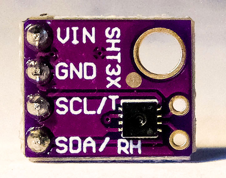
I2C with the ATtiny85 – SHT31 temperature and humidity sensor
The second library I modified is Grove_SHT31_Temp_Humi_Sensor by Seeed Studio, version 1.0.0. It is used to control a SHT31 temperature and humidity sensor.
Here, too, the reference to the license.
Modifying SHT31.h
Modifying the header file is even easier because the wire object is not passed in this library. You just have to replace #include "Wire.h" with #include<TinyWireM.h> in SHT31.h.
#ifndef _SHT31_H_
#define _SHT31_H_

#include "Arduino.h"
//////// #include "Wire.h" /////// take out
#include<TinyWireM.h> /////// Add!

#define SHT31_ADDR    0x44
#define SHT31_MEAS_HIGHREP_STRETCH 0x2C06
#define SHT31_MEAS_MEDREP_STRETCH  0x2C0D
#define SHT31_MEAS_LOWREP_STRETCH  0x2C10
#define SHT31_MEAS_HIGHREP         0x2400
#define SHT31_MEAS_MEDREP          0x240B
#define SHT31_MEAS_LOWREP          0x2416
#define SHT31_READSTATUS           0xF32D
#define SHT31_CLEARSTATUS          0x3041
#define SHT31_SOFTRESET            0x30A2
#define SHT31_HEATEREN             0x306D
#define SHT31_HEATERDIS            0x3066

class SHT31 {
  public:
    SHT31();
    boolean begin(uint8_t i2caddr = SHT31_ADDR);
    float getTemperature(void);
    float getHumidity(void);
    uint16_t readStatus(void);
    void reset(void);
    void heater(boolean);
    uint8_t crc8(const uint8_t *data, int len);

  private:
    boolean getTempHum(void);
    void writeCommand(uint16_t cmd);

    uint8_t _i2caddr;
    float humidity, temp;

};

#endif
Modifying SHT31.cpp
There is a little more to change in SHT31.cpp, but it is not complicated. Keep an eye out for “Wire” again.
#include "SHT31.h"

SHT31::SHT31() {
}

boolean SHT31::begin(uint8_t i2caddr) {
  /////// Wire.begin(); //////// Take out!!!!
  //TinyWireM.begin(); -> not necessary to put in!
  _i2caddr = i2caddr;
  reset();
  /////// return (readStatus() == 0x40); /////// Take out!!!!
  return true; //////// Add!!!!
}

float SHT31::getTemperature(void) {
  if (! getTempHum()) return NAN;
  return temp;
}


float SHT31::getHumidity(void) {
  if (! getTempHum()) return NAN;
  return humidity;
}

uint16_t SHT31::readStatus(void) {
  return 42; /////// I added this line. Without this, it compiles
             /////// with an Arduino Nano, but not with an ATtiny85
}

void SHT31::reset(void) {
  writeCommand(SHT31_SOFTRESET);
  delay(10);
}

void SHT31::heater(boolean h) {
  if (h)
    writeCommand(SHT31_HEATEREN);
  else
    writeCommand(SHT31_HEATERDIS);
}

uint8_t SHT31::crc8(const uint8_t *data, int len) {
  const uint8_t POLYNOMIAL(0x31);
  uint8_t crc(0xFF);

  for ( int j = len; j; --j ) {
      crc ^= *data++;

      for ( int i = 8; i; --i ) {
  crc = ( crc & 0x80 )
    ? (crc << 1) ^ POLYNOMIAL
    : (crc << 1);
      }
  }
  return crc;
}


boolean SHT31::getTempHum(void) {
  uint8_t readbuffer[6];

  writeCommand(SHT31_MEAS_HIGHREP);

  delay(50);
  /////// Wire.requestFrom(_i2caddr, (uint8_t)6); /////// Take out!!!!
  TinyWireM.requestFrom(_i2caddr,6); //////// Add!!!!
  //if (Wire.available() != 6) /////// Take out!!!!
  if (TinyWireM.available() != 6)
    return false;
  for (uint8_t i=0; i<6; i++) {
    //readbuffer[i] = Wire.read(); /////// Take out!!!!
  readbuffer[i] = TinyWireM.receive(); /////// Add!!!!
  }
  uint16_t ST, SRH;
  ST = readbuffer[0];
  ST <<= 8;
  ST |= readbuffer[1];

  if (readbuffer[2] != crc8(readbuffer, 2)) return false;

  SRH = readbuffer[3];
  SRH <<= 8;
  SRH |= readbuffer[4];

  if (readbuffer[5] != crc8(readbuffer+3, 2)) return false;

  double stemp = ST;
  stemp *= 175;
  stemp /= 0xffff;
  stemp = -45 + stemp;
  temp = stemp;

  double shum = SRH;
  shum *= 100;
  shum /= 0xFFFF;

  humidity = shum;

  return true;
}

void SHT31::writeCommand(uint16_t cmd) {
  /* Wire.beginTransmission(_i2caddr); /////// Take out 4 lines !!!!
  Wire.write(cmd >> 8);
  Wire.write(cmd & 0xFF);
  Wire.endTransmission();     */
  TinyWireM.beginTransmission(_i2caddr); /////// Add the following lines!!!!
  TinyWireM.send((uint8_t)(cmd >> 8));
  TinyWireM.send((uint8_t)(cmd & 0xFF));
  TinyWireM.endTransmission();
}
Sketch sht31
Then there is still a test sketch to create, which is not difficult. To do this, simply find the relevant functions from the example sketch. The result could then look like this:
#include <TinyWireM.h>
#include <Tiny4kOLED.h>
#include <SHT31.h>
uint8_t width = 128;
uint8_t height = 64;
SHT31 sht31 = SHT31();
void setup() {
TinyWireM.begin();
oled.begin(width, height, sizeof(tiny4koled_init_128x64br), tiny4koled_init_128x64br);
oled.setFont(FONT6X8);
oled.clear();
oled.on();
oled.setCursor(0, 0);
sht31.begin();
sht31.heater(false); // heater off, with "true" it's on -> can remove condensated water,
// but gives false temperature values (about 3 degrees too high);
}
void loop() {
float temp = sht31.getTemperature();
float hum = sht31.getHumidity();
oled.setCursor(0,0);
oled.print("Temp. [*C]: ");
oled.print(temp);
oled.clearToEOL();
oled.setCursor(0,2); //10
oled.print("Humidity [%]: ");
oled.print(hum);
oled.clearToEOL();
delay(2000);
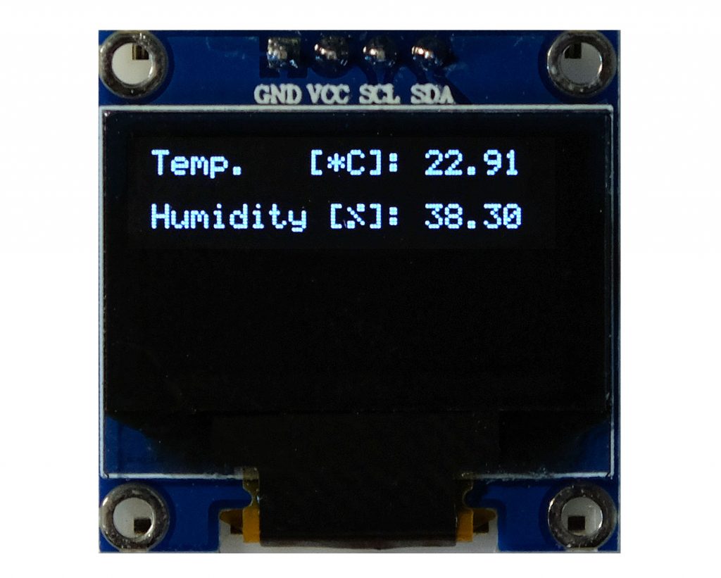
}
By the way, this sketch requires only 62% of the program memory. And here is the output:
Acknowledgement
I would like to thank the authors of the libraries TinyWireM, Tiny4kOLED, MPU6050_light and Grove_SHT31_Temp_Humi_Sensor.
is there a possibility to access to I2C address of ssd1306 128×64 display under libraries TinyWireM, and tiny4koled.
Thanks
Full Thanks for such tutorials, and solutions
Thank you for your kind comment – very motivating for me!
is there a possibility to access to I2C address of ssd1306 128×64 display under libraries TinyWireM, and tiny4koled.
Thanks
I am not sure I know what you want exactly. But what I can say is that the I2C address of the SS1306 is fixed in the Tiny4kOLED library. You can find the address definition (0x3C) here:
https://github.com/datacute/Tiny4kOLED/blob/master/src/Tiny4kOLED_common.h
in line 62.
I connected an ATtiny85 to SSD Oled 128×32 with the following pins :
Gnd, Vcc, D0, D1, Res, DC, and CS .
I2c communication was configured by moving R3 to R1 , and R8 shorten.
The ATtinyCore package was installed via Ide 1.8
libraries TinyWireM, and Tiny4koled installed
PB0 –>D1
PB2–>CLK
Res –> Vcc
DC , and CS –> Gnd
in such configuration is the address (0x3C) still always correct?
I have not yet worked with the displays that have these pins, but I have found information here:
https://learn.adafruit.com/monochrome-oled-breakouts/arduino-library-and-examples
Depending on the model you have, you might need to solder some jumpers. But I suggest read the article first. Hope this helps.
Thank you so for kind help
Another excellent article that stimulates thoughts of how the ATtiny devices could be used. I already use your MCP23017 and INA219 libraries on my ESP projects and I find they work really well. I use platformIO to build my projects. I am aout to use your MCP23017 library with an ESP-Now project in which an ESP32 will be a bridge to MQTT and five ESP8266 devices communicate with the bridge with bi-directional control. The bridge does ESP-Now and WiFi simulataneously.
Keep up the great work you do, I really like the style of your writing and how well you describe the subject material.
Thank you so much for your kind feedback! Best, wishes, Wolfgang