Über den Beitrag
Im letzten Beitrag hatte ich über die Programmierung von ATtinys mithilfe von ATTinyCore berichtet. Dieses Paket ermöglicht die Nutzung der USI Schnittstelle der ATtinys für den I2C Gebrauch mit der Wire Bibliothek. Spezielle Bibliotheken für die I2C Implementierung, wie TinyWireM, TinyI2C oder USIWire sind damit nicht mehr zwingend erforderlich. Da sie jedoch schlanker sind, kann ihr Einsatz auf den ATtinys mit ihrem begrenzten Programmspeicher trotzdem sinnvoll sein.
Ich gehe in diesem Beitrag am Beispiel der TinyWireM Bibliothek von Adafruit der Frage nach, wie groß die Einsparung gegenüber Wire ist. Außerdem stelle ich TinyWireM kompatible Bibliotheken für einige I2C basierte Bauteile vor. Und schließlich zeige ich noch an zwei Beispielen, dass man viele I2C basierte Bibliotheken ohne großen Aufwand mit TinyWireM verträglich machen kann.
TinyWireM und TinyWireS
Das „M“ in TinyWireM steht für Master. Das heißt, die Bibliothek ermöglicht es, den ATtiny zum I2C Master zu machen, aber nicht zum Slave. Dafür gibt es verschiedene andere Bibliotheken wie TinyWireS. Wenn ihr beispielsweise zwei ATtinys über I2C miteinander kommunizieren lassen wolltet, dann bräuchtet ihr beide Varianten. Ich beschränke mich hier auf den Einsatz der ATtinys als Master.
Vorbereitungen und Voraussetzungen
Ich gehe davon aus, dass ihr das Paket ATTinyCore von Spence Konde installiert habt. Außerdem setze ich voraus, dass ihr wisst, wie ihr damit Bootloader brennt und Sketche hochladet. Falls das nicht der Fall ist, schaut einfach in meinen letzten Beitrag, in dem ich das alles detailliert erklärt habe.
Zudem solltet ihr TinyWireM installiert haben. Ihr bekommt die Bibliothek über die Bibliotheksverwaltung der Arduino IDE. Alternativ könnt ihr die Bibliothek hier direkt von GitHub herunterladen.
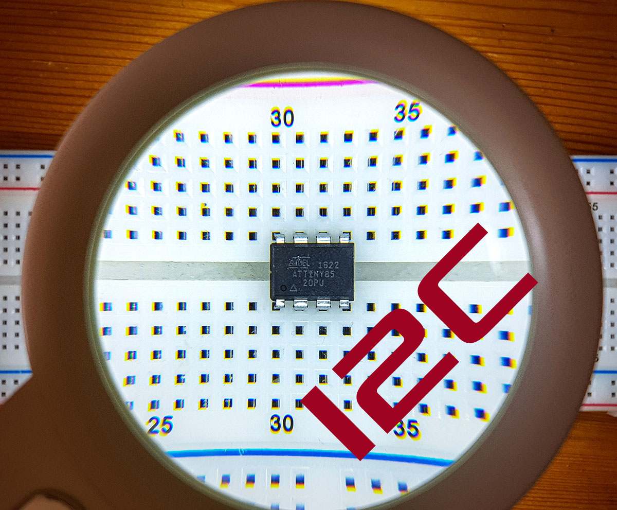
Für den Beitrag verwende ich einen ATtiny85. Ihr könnt genauso gut einen anderen ATtiny nehmen, der mit ATTinyCore kompatibel ist. Es sollte aber schon ein Vertreter mit 8 kByte Programmspeicher sein, sonst wird es zu eng für einige Beispiele.

Verwendung von TinyWireM und Wire am Beispiel MPU6050
In den meisten Fällen verwendet ihr für I2C Bauteile sicherlich Bibliotheken, die es euch abnehmen, die Bauteile auf Registerebene mithilfe der Wire Funktionen anzusprechen. Um die Unterschiede zwischen TinyWireM und Wire zu verstehen, schauen wir uns jetzt aber ein Beispiel an, bei dem wir keine Bauteil-Bibliothek verwenden.
Als Anschauungsobjekt habe ich das 6-Achsen Gyroskop- und Beschleunigungssensor-Modul MPU6050 ausgesucht. Wer sich für die Details dieses Bauteils interessiert, kann meinen Beitrag dazu lesen. Hier und jetzt geht es nur darum, TinyWireM und Wire in Aktion zu sehen.
Da ich die Messwerte des MPU6050 auf dem seriellen Monitor ausgeben möchte, habe ich den Optiboot Bootloader auf den ATtiny85 gebrannt und die Sketche mit einem USB-zu-TTL Serial Adapter hochgeladen. Dabei kam die folgende Schaltung zum Einsatz:

MPU6050 Steuerung mit Wire
Der folgende Sketch benutzt die Wire Bibliothek für die I2C Kommunikation. Im Setup wird der MPU6050 „geweckt“. In Loop werden dann die drei Beschleunigungswerte, die Temperatur und die drei Gyroskopwerte hintereinander ausgelesen. Da es sich um 16-Bit Werte handelt, müssen jeweils zwei Register gelesen werden, also insgesamt vierzehn. Dann werden die Werte auf dem seriellen Monitor ausgegeben.
#include<Wire.h>
#define MPU6050_ADDR 0x68

int16_t AcX,AcY,AcZ,Tmp,GyX,GyY,GyZ;
void setup(){
  Wire.begin();
  Wire.beginTransmission(MPU6050_ADDR);
  Wire.write(0x6B);  // PWR_MGMT_1 register
  Wire.write(0);     // set to zero (wakes up the MPU6050)
  Wire.endTransmission(true);
  Serial.begin(9600);
}
void loop(){
  Wire.beginTransmission(MPU6050_ADDR);
  Wire.write(0x3B);  // starting with register 0x3B (ACCEL_XOUT_H)
  Wire.endTransmission(false);
  Wire.requestFrom(MPU6050_ADDR,14,true);  // request a total of 14 registers
  AcX=Wire.read()<<8|Wire.read();  // 0x3B (ACCEL_XOUT_H) & 0x3C (ACCEL_XOUT_L)
  AcY=Wire.read()<<8|Wire.read();  // 0x3D (ACCEL_YOUT_H) & 0x3E (ACCEL_YOUT_L)
  AcZ=Wire.read()<<8|Wire.read();  // 0x3F (ACCEL_ZOUT_H) & 0x40 (ACCEL_ZOUT_L)
  Tmp=Wire.read()<<8|Wire.read();  // 0x41 (TEMP_OUT_H) & 0x42 (TEMP_OUT_L)
  GyX=Wire.read()<<8|Wire.read();  // 0x43 (GYRO_XOUT_H) & 0x44 (GYRO_XOUT_L)
  GyY=Wire.read()<<8|Wire.read();  // 0x45 (GYRO_YOUT_H) & 0x46 (GYRO_YOUT_L)
  GyZ=Wire.read()<<8|Wire.read();  // 0x47 (GYRO_ZOUT_H) & 0x48 (GYRO_ZOUT_L)
  delay(2000);
  Serial.println();
  Serial.print(F("AcX = ")); Serial.print(AcX);
  Serial.print(F(" | AcY = ")); Serial.print(AcY);
  Serial.print(F(" | AcZ = ")); Serial.print(AcZ);
  Serial.print(F(" | Tmp = ")); Serial.print(Tmp/340.00+36.53);  //equation for temperature in degrees C from datasheet
  Serial.print(F(" | GyX = ")); Serial.print(GyX);
  Serial.print(F(" | GyY = ")); Serial.print(GyY);
  Serial.print(F(" | GyZ = ")); Serial.println(GyZ);
}
Der Sketch benötigt 4058 Bytes. Das sind ~53% des verfügbaren Programmspeichers (7616 Bytes). Zur Erinnerung: Eigentlich stehen 8192 Bytes zur Verfügung, aber der Optiboot Bootloader benötigt 576 Bytes.

Der Vollständigkeit halber hier noch die Ausgabe:
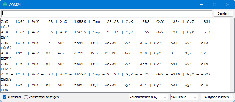
Die hässlichen Sonderzeichen sind übrigens dem Umstand geschuldet, dass der Pin PB0 sowohl SDA Anschluss, wie auch serieller Ausgang zum Adapter ist. Wenn euch das stört, dann könnt ihr die Ausgabe auch über SoftwareSerial vornehmen, beispielsweise mit den Pins PB3 und PB4. Allerdings müsst ihr dann nach dem Hochladen umstecken und verbraucht mehr Programmspeicher (insgesamt 4898 Bytes).
MPU6050 Steuerung mit TinyWireM
Auch wenn sich TinyWireM von Wire unter der Haube sehr unterscheidet, ist die Bedienung doch recht ähnlich. Die TinyWireM Funktionen haben aber teilweise andere Namen:

Hier die „Übersetzung“ des Sketches für TinyWireM:
#include <TinyWireM.h>
#define MPU6050_ADDR 0x68

int16_t AcX,AcY,AcZ,Tmp,GyX,GyY,GyZ;
void setup(){
  TinyWireM.begin();
  TinyWireM.beginTransmission(MPU6050_ADDR);
  TinyWireM.send(0x6B);  // PWR_MGMT_1 register
  TinyWireM.send(0);     // set to zero (wakes up the MPU-6050)
  TinyWireM.endTransmission(true);
  Serial.begin(9600);
}
void loop(){
  TinyWireM.beginTransmission(MPU6050_ADDR);
  TinyWireM.send(0x3B);  // starting with register 0x3B (ACCEL_XOUT_H)
  TinyWireM.endTransmission(false);
  TinyWireM.requestFrom(MPU6050_ADDR,14);  // request a total of 14 registers
  AcX=TinyWireM.receive()<<8|TinyWireM.receive();  // 0x3B (ACCEL_XOUT_H) & 0x3C (ACCEL_XOUT_L)
  AcY=TinyWireM.receive()<<8|TinyWireM.receive();  // 0x3D (ACCEL_YOUT_H) & 0x3E (ACCEL_YOUT_L)
  AcZ=TinyWireM.receive()<<8|TinyWireM.receive();  // 0x3F (ACCEL_ZOUT_H) & 0x40 (ACCEL_ZOUT_L)
  Tmp=TinyWireM.receive()<<8|TinyWireM.receive();  // 0x41 (TEMP_OUT_H) & 0x42 (TEMP_OUT_L)
  GyX=TinyWireM.receive()<<8|TinyWireM.receive();  // 0x43 (GYRO_XOUT_H) & 0x44 (GYRO_XOUT_L)
  GyY=TinyWireM.receive()<<8|TinyWireM.receive();  // 0x45 (GYRO_YOUT_H) & 0x46 (GYRO_YOUT_L)
  GyZ=TinyWireM.receive()<<8|TinyWireM.receive();  // 0x47 (GYRO_ZOUT_H) & 0x48 (GYRO_ZOUT_L)
  delay(2000);
  Serial.println();
  Serial.print(F("AcX = ")); Serial.print(AcX);
  Serial.print(F(" | AcY = ")); Serial.print(AcY);
  Serial.print(F(" | AcZ = ")); Serial.print(AcZ);
  Serial.print(F(" | Tmp = ")); Serial.print(Tmp/340.00+36.53);  //equation for temperature in degrees C from datasheet
  Serial.print(F(" | GyX = ")); Serial.print(GyX);
  Serial.print(F(" | GyY = ")); Serial.print(GyY);
  Serial.print(F(" | GyZ = ")); Serial.println(GyZ);
}
Dieser Sketch braucht lediglich 3538 Bytes, also 520 Bytes weniger. Das entspricht ungefähr einem Sechzehntel des 8 kByte Programmspeichers. Bei einem ATtiny45 wäre es dann schon ein Achtel. Das klingt vielleicht nicht nach viel, es könnten aber genau die Bytes sein, die darüber entscheiden, welchen ATtiny ihr verwenden könnt.

TinyWireM kompatible Bibliotheken
Wie ihr gerade gesehen habt, könnt ihr mit TinyWireM wertvollen Programmspeicher sparen. Ihr habt aber auch gesehen, dass die Funktionsaufrufe von TinyWireM und Wire unterschiedlich sind. Für die Ansteuerung eines I2C basierten Bauteils dürft ihr also nicht einfach nur TinyWireM.h anstelle von Wire.h einbinden. Die Bibliothek muss entweder für TinyWireM geschrieben sein oder den Gebrauch als Option zulassen. Dafür möchte ich einige Beispiele zeigen. Ihr findet alle verwendeten Bibliotheken auf GitHub oder installiert sie über die Bibliotheksverwaltung der Arduino IDE.
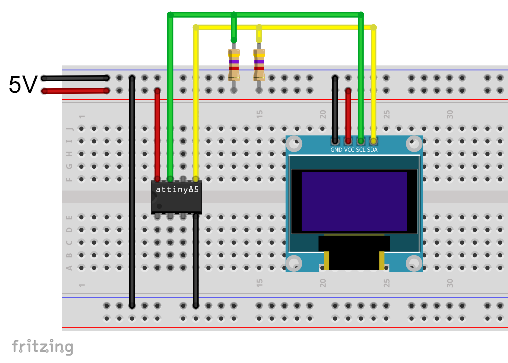
1. OLED Display Steuerung mit Tiny4kOLED
Mein erstes Beispiel ist die Bibliothek Tiny4kOLED, mit der ihr kleine, I2C basierte OLED Displays steuern könnt. Die Displays gibt es mit 128 x 64 oder 128 x 32 Pixeln. Üppig ist das nicht, aber ausreichend, um beispielsweise ein paar Messwerte anzuzeigen.
Da wir den seriellen Monitor nicht mehr brauchen, habe ich bei allen kommenden Beispiele den ATtiny85 über ISP ohne Bootloader programmiert.
Folgende Schaltung kam für den Betrieb des Displays zum Einsatz:
Ich werde nicht in die Details der Tiny4kOLED Bibliothek einsteigen. Dafür gibt es viele gute Beispielsketche. Hier nur ein kleiner „Hello World“ Sketch zur Anschauung und als Test:
#include <TinyWireM.h>
#include <Tiny4kOLED.h>

uint8_t width = 128;
uint8_t height = 64;

void setup() {
  TinyWireM.begin();
  oled.begin(width, height, sizeof(tiny4koled_init_128x64br), tiny4koled_init_128x64br);
  oled.clear();
  oled.setFont(FONT6X8);
  oled.on();
  oled.setCursor(30, 4); // x: pixel / y: line
  oled.print("Hello world");
}

void loop() {
}
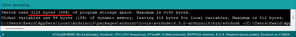
Der Sketch benötigt 2682 Bytes, also ~32% des Programmspeichers.

Und so sieht die Ausgabe auf dem Display aus:

Zum Vergleich: Ansteuerung mit SSD1306Acii und Wire
Zum Vergleich habe ich eine schlanke Wire basierte Bibliothek, nämlich SSD1306Ascii ausprobiert:
#include <Wire.h>
#include "SSD1306Ascii.h"
#include "SSD1306AsciiWire.h"
#define I2C_ADDRESS 0x3C

SSD1306AsciiWire oled;

void setup() {
  Wire.begin();
  oled.begin(&Adafruit128x64, I2C_ADDRESS);
  oled.setFont(System5x7);
  oled.clear();
  oled.setCursor(30,4);
  oled.print("Hello world!");
}

void loop() {}
Der Unterschied zur Tiny4kOLED Lösung betrug immerhin 442 Bytes:
2. Steuerung des MCP23017 Portexpanders
Wechseln zwischen Wire und TinyWireM
Ich habe drei meiner Bibliotheken so umgeschrieben, dass sie sowohl mit Wire wie auch mit TinyWireM funktionieren. Dazu habe ich den Bibliotheken jeweils eine Datei namens Bauteil_config.h (also z.B. MCP23017_config.h) hinzugefügt, in der ihr lediglich die Zeile #define USE_TINY_WIRE_M_ entkommentieren müsst, um auf die TinyWireM Bibliothek zu wechseln. Die Config-Dateien findet ihr im Arduino „libraries“ Ordner → Bibliotheksname → src.
Über die Präprozessordirektiven #ifdef (if defined), #ifndef (if not defined), #else und #endif wird gesteuert, welcher Code compiliert und welcher ignoriert wird. Hier ein Ausschnitt:
#ifndef USE_TINY_WIRE_M_
        _wire->beginTransmission(I2C_Address);
        _wire->write(reg);
        _wire->endTransmission(false);
        _wire->requestFrom(I2C_Address, 1);
        regVal = _wire->read();
#else
        TinyWireM.beginTransmission(I2C_Address);
        TinyWireM.send(reg);
        TinyWireM.endTransmission();
        TinyWireM.requestFrom(I2C_Address, 1);
        regVal = TinyWireM.receive();
#endif
Ihr dürft nur nicht vergessen, #define USE_TINY_WIRE_M_ wieder herauszukommentieren, wenn ihr den Mikrocontroller wechselt und Wire benutzen wollt.
Ich hatte übrigens zunächst versucht, #define USE_TINY_WIRE_M_ einfach in den Sketch zu schreiben. Dabei habe ich gelernt, dass der Präprozessor beim Lesen des Sketches nicht zeilenweise vorgeht, sondern anscheinend erst die include-Dateien liest. Dadurch war USE_TINY_WIRE_M_ zunächst nicht definiert, was zu entsprechenden Fehlermeldungen führte. Deswegen der umständliche Weg über die Config-Datei.
Und nun zur Bibliothek MCP23017_WE
Die Bibliothek MCP23017_WE dient der Ansteuerung des MCP23017 Portexpanders, mit dem ihr zusätzliche 16 GPIOs zur Verfügung habt. Für Details schaut in meinen Beitrag zu diesem Bauteil. Zum Test der Ansteuerung per ATtiny85 kam (im Prinzip) die folgende Schaltung zum Einsatz:
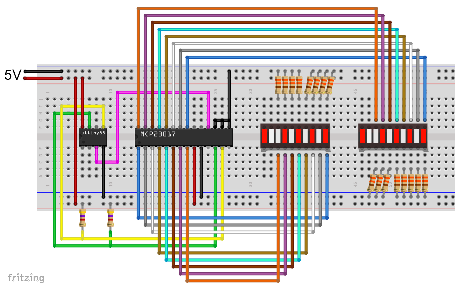
Da ich bequem bin, habe ich LED Bars mit gemeinsamer Kathode und integrierten Widerständen verwendet:

Und hier der Beispielsketch:
#include <TinyWireM.h>
#include <MCP23017_WE.h>
#define MCP_ADDRESS 0x20 // (A2/A1/A0 = LOW)
#define RESET_PIN 4

typedef MCP23017_WE MCP;
MCP myMCP = MCP(MCP_ADDRESS, RESET_PIN);

int wT = 1000; // wT = waiting time

void setup(){
  TinyWireM.begin();
  myMCP.Init();
  myMCP.setPortMode(0b11111101, MCP::A);  // Port A: all pins are OUTPUT except pin 1
  myMCP.setPortMode(0b11111111, MCP::B);  // Port B: all pins are OUTPUT
  delay(wT);
  myMCP.setAllPins(MCP::A, MCP::ON); // alle LEDs switched on except A1
  delay(wT);
  myMCP.setPinX(1, MCP::A, OUTPUT, HIGH); // A1 switched on
  delay(wT);
  myMCP.setPort(0b11110000, MCP::B); // B4 - B7 switched on
  delay(wT);
  myMCP.setPort(0b01011110, MCP::A); // A0,A5,A7 switched off
  delay(wT);
  myMCP.setPinX(0, MCP::B, OUTPUT, HIGH); // B0 switched on
  delay(wT);
  myMCP.setPinX(4, MCP::B, OUTPUT, LOW); // B4 switched off
  delay(wT);
  myMCP.setAllPins(MCP::A, HIGH); // A0 - A7 all on
  delay(wT);
  myMCP.setPin(3, MCP::A, LOW); // A3 switched off
  delay(wT);
  myMCP.setPortX(0b11110000, 0b01101111, MCP::B); // at port B only B5,B6 are switched on
  delay(wT);
  myMCP.setPinMode(0, MCP::B, OUTPUT); // B0 --> OUTPUT
  for(int i=0; i<5; i++){  // B0 blinking
    myMCP.togglePin(0, MCP::B);
    delay(200);
    myMCP.togglePin(0, MCP::B);
    delay(200);
  }
  for(int i=0; i<5; i++){ // B7 blinking
    myMCP.togglePin(7, MCP::B);
    delay(200);
    myMCP.togglePin(7, MCP::B);
    delay(200);
  }
}

void loop(){
}
Der Speicherbedarf des Sketches beträgt 2106 Bytes, also ca. 25 Prozent.
3. Den INA219 Stromsensor steuern
Die Bibliothek INA219_WE dient der Ansteuerung des Stromsensors INA219, über den ich hier im Detail berichtet habe.

Das ist die Schaltung, die zum Einsatz kam:

Das Bauteil „Load“ (Last) steht dabei für einen beliebigen Verbraucher.
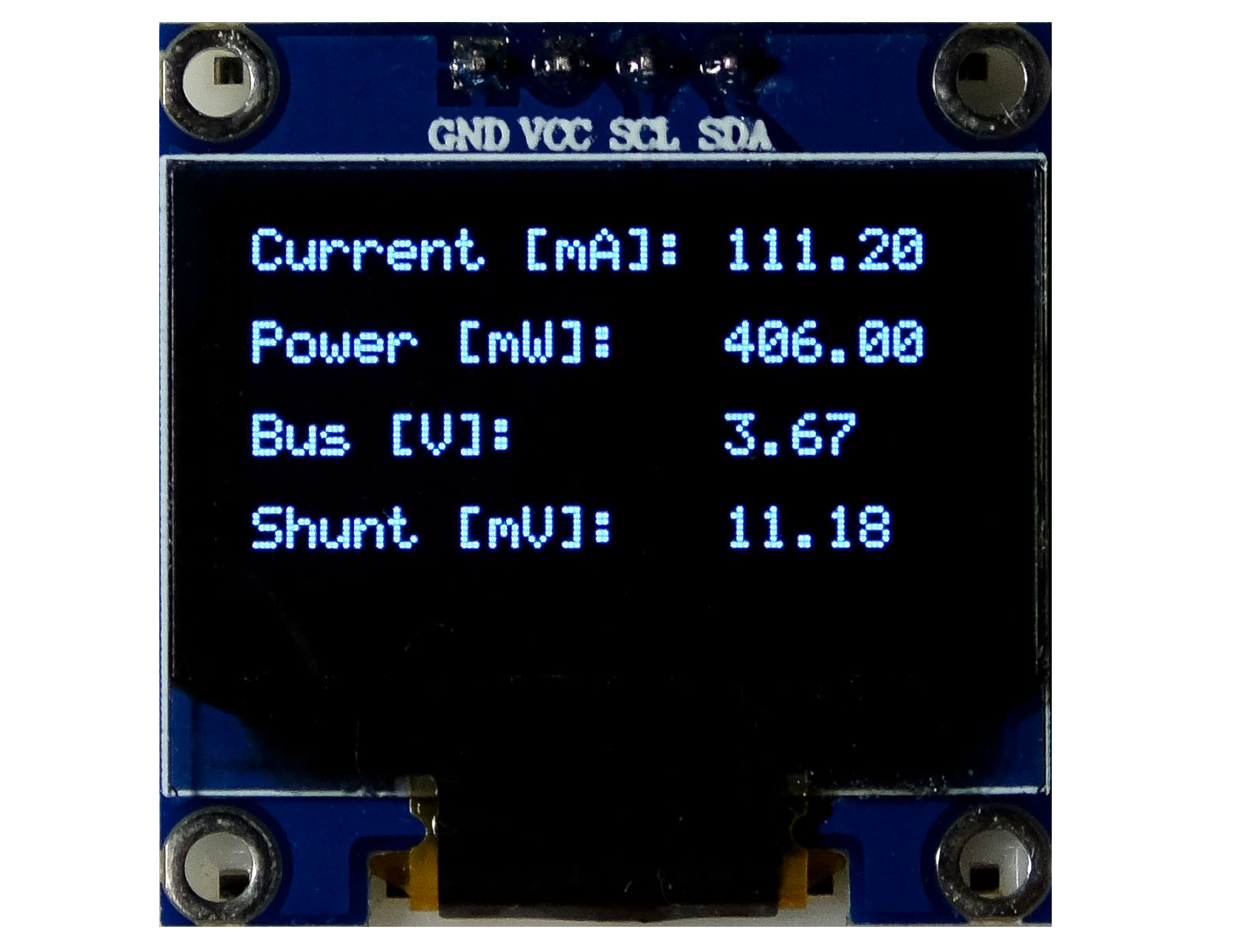
Und hier nun der Beispielsketch, der 72 Prozent des Programmspeichers des ATtiny85 belegt:
#include <TinyWireM.h>
#include <Tiny4kOLED.h>
#include <INA219_WE.h>
#define I2C_ADDRESS 0x40

uint8_t width = 128;
uint8_t height = 64;

/* There are several ways to create your INA219 object:
 * INA219_WE ina219 = INA219_WE()              -> uses I2C Address = 0x40
 * INA219_WE ina219 = INA219_WE(ICM20948_ADDR) -> define I2C_ADDRESS
 */
INA219_WE ina219 = INA219_WE(I2C_ADDRESS);

void setup() {
  TinyWireM.begin();
  oled.begin(width, height, sizeof(tiny4koled_init_128x64br), tiny4koled_init_128x64br);
  oled.setFont(FONT6X8);
  oled.clear();
  oled.on();

  oled.setCursor(0, 0);
  if(!ina219.init()){
     oled.print("INA219 not connected!");
     while(1){}
  }
  else{
    oled.print("INA219 connected");
    delay(1000);
    oled.clear();
  }

  /* Set ADC Mode for Bus and ShuntVoltage
  * Mode *            * Res / Samples *       * Conversion Time *
  BIT_MODE_9        9 Bit Resolution             84 µs
  BIT_MODE_10       10 Bit Resolution            148 µs
  BIT_MODE_11       11 Bit Resolution            276 µs
  BIT_MODE_12       12 Bit Resolution            532 µs  (DEFAULT)
  SAMPLE_MODE_2     Mean Value 2 samples         1.06 ms
  SAMPLE_MODE_4     Mean Value 4 samples         2.13 ms
  SAMPLE_MODE_8     Mean Value 8 samples         4.26 ms
  SAMPLE_MODE_16    Mean Value 16 samples        8.51 ms
  SAMPLE_MODE_32    Mean Value 32 samples        17.02 ms
  SAMPLE_MODE_64    Mean Value 64 samples        34.05 ms
  SAMPLE_MODE_128   Mean Value 128 samples       68.10 ms
  */
  //ina219.setADCMode(SAMPLE_MODE_128); // choose mode and uncomment for change of default

  /* Set measure mode
  POWER_DOWN - INA219 switched off
  TRIGGERED  - measurement on demand
  ADC_OFF    - Analog/Digital Converter switched off
  CONTINUOUS  - Continuous measurements (DEFAULT)
  */
  // ina219.setMeasureMode(CONTINUOUS); // choose mode and uncomment for change of default

  /* Set PGain
  * Gain *  * Shunt Voltage Range *   * Max Current (if shunt is 0.1 ohms) *
   PG_40       40 mV                    0.4 A
   PG_80       80 mV                    0.8 A
   PG_160      160 mV                   1.6 A
   PG_320      320 mV                   3.2 A (DEFAULT)
  */
  // ina219.setPGain(PG_320); // choose gain and uncomment for change of default

  /* Set Bus Voltage Range
   BRNG_16   -> 16 V
   BRNG_32   -> 32 V (DEFAULT)
  */
  // ina219.setBusRange(BRNG_32); // choose range and uncomment for change of default

  /* If the current values delivered by the INA219 differ by a constant factor
     from values obtained with calibrated equipment you can define a correction factor.
     Correction factor = current delivered from calibrated equipment / current delivered by INA219
  */
  // ina219.setCorrectionFactor(0.98); // insert your correction factor if necessary

  /* If you experience a shunt voltage offset, that means you detect a shunt voltage which is not
     zero, although the current should be zero, you can apply a correction. For this, uncomment the
     following function and apply the offset you have detected.
  */
  // ina219.setShuntVoltOffset_mV(0.5); // insert the shunt voltage (millivolts) you detect at zero current
}

void loop() {
  float shuntVoltage_mV = 0.0;
  float loadVoltage_V = 0.0;
  float busVoltage_V = 0.0;
  float current_mA = 0.0;
  float power_mW = 0.0;
  bool ina219_overflow = false;

  shuntVoltage_mV = ina219.getShuntVoltage_mV();
  busVoltage_V = ina219.getBusVoltage_V();
  current_mA = ina219.getCurrent_mA();
  power_mW = ina219.getBusPower();
  //loadVoltage_V  = busVoltage_V + (shuntVoltage_mV/1000);
  //ina219_overflow = ina219.getOverflow();

  oled.setCursor(0,0);
  oled.print("Current [mA]: ");
  oled.print(current_mA);
  oled.clearToEOL();

  oled.setCursor(0,2); //10
  oled.print("Power [mW]:   ");
  oled.print(power_mW);
  oled.clearToEOL();

  oled.setCursor(0,4);
  oled.print("Bus [V]:      ");
  oled.print(busVoltage_V);
  oled.clearToEOL();

  oled.setCursor(0,6);
  oled.print("Shunt [mV]:   ");
  oled.print(shuntVoltage_mV);
  oled.clearToEOL();

  delay(3000);
}
Bevor ihr den Sketch anwendet, müsst ihr wieder in der Datei INA219_config.h die Zeile #define USE_TINY_WIRE_M_ entkommentieren.
Die Ausgabe sah wie folgt aus:
4. Steuerung des ADS1115 A/D-Wandler
Zu guter Letzt habe ich noch meine Bibliothek ADS1115_WE angepasst. Mit ihr steuert ihr den 16-Bit, 4-Kanal A/D-Wandler ADS1115. Über dieses schöne Bauteil habe ich hier berichtet.
Folgende Schaltung kam zum Einsatz:
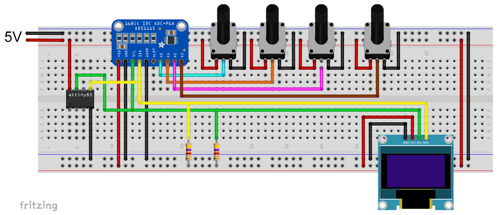
Dabei stehen die vier Potis stellvertretend für eine zu messende Spannung.
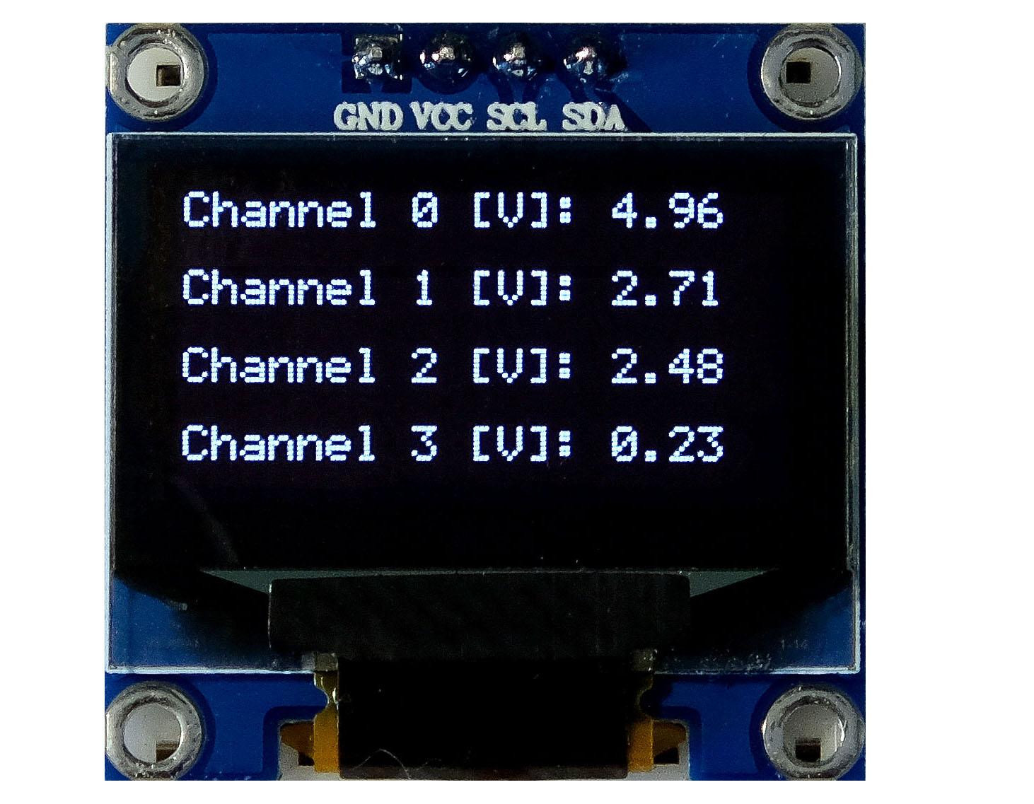
Und das war mein Testsketch, der 73 Prozent des Programmspeichers belegte:
#include <TinyWireM.h>
#include <Tiny4kOLED.h>
#include<ADS1115_WE.h>
#define ADS1115_I2C_ADDR 0x48
uint8_t width = 128;
uint8_t height = 64;

/* There are two ways to create your ADS1115_WE object:
 * ADS1115_WE adc = ADS1115_WE()             -> uses Wire / I2C Address = 0x48
 * ADS1115_WE adc = ADS1115_WE(I2C_ADDRESS)  -> uses Wire / I2C_ADDRESS
 */
ADS1115_WE adc = ADS1115_WE(ADS1115_I2C_ADDR);

void setup() {
  TinyWireM.begin();
  oled.begin(width, height, sizeof(tiny4koled_init_128x64br), tiny4koled_init_128x64br);
  oled.clear();
  oled.setFont(FONT6X8);
  oled.on();

  if(!adc.init()){
     oled.print("ADS1115 not connected");
     while(1){}
  }
  else{
    oled.print("ADS1115 connected");
    delay(1000);
    oled.clear();
  }

  /* Set the voltage range of the ADC to adjust the gain
   * Please note that you must not apply more than VDD + 0.3V to the input pins!
   *
   * ADS1115_RANGE_6144  ->  +/- 6144 mV
   * ADS1115_RANGE_4096  ->  +/- 4096 mV
   * ADS1115_RANGE_2048  ->  +/- 2048 mV (default)
   * ADS1115_RANGE_1024  ->  +/- 1024 mV
   * ADS1115_RANGE_0512  ->  +/- 512 mV
   * ADS1115_RANGE_0256  ->  +/- 256 mV
   */
  adc.setVoltageRange_mV(ADS1115_RANGE_6144); //comment line/change parameter to change range

  /* Set the inputs to be compared
   *
   *  ADS1115_COMP_0_1    ->  compares 0 with 1 (default)
   *  ADS1115_COMP_0_3    ->  compares 0 with 3
   *  ADS1115_COMP_1_3    ->  compares 1 with 3
   *  ADS1115_COMP_2_3    ->  compares 2 with 3
   *  ADS1115_COMP_0_GND  ->  compares 0 with GND
   *  ADS1115_COMP_1_GND  ->  compares 1 with GND
   *  ADS1115_COMP_2_GND  ->  compares 2 with GND
   *  ADS1115_COMP_3_GND  ->  compares 3 with GND
   */
  adc.setCompareChannels(ADS1115_COMP_0_GND); //comment line/change parameter to change channel

  /* Set number of conversions after which the alert pin asserts
   * - or you can disable the alert
   *
   *  ADS1115_ASSERT_AFTER_1  -> after 1 conversion
   *  ADS1115_ASSERT_AFTER_2  -> after 2 conversions
   *  ADS1115_ASSERT_AFTER_4  -> after 4 conversions
   *  ADS1115_DISABLE_ALERT   -> disable comparator / alert pin (default)
   */
  //adc.setAlertPinMode(ADS1115_ASSERT_AFTER_1); //uncomment if you want to change the default

  /* Set the conversion rate in SPS (samples per second)
   * Options should be self-explaining:
   *
   *  ADS1115_8_SPS
   *  ADS1115_16_SPS
   *  ADS1115_32_SPS
   *  ADS1115_64_SPS
   *  ADS1115_128_SPS (default)
   *  ADS1115_250_SPS
   *  ADS1115_475_SPS
   *  ADS1115_860_SPS
   */
  // adc.setConvRate(ADS1115_8_SPS); //uncomment if you want to change the default

  /* Set continuous or single shot mode:
   *
   *  ADS1115_CONTINUOUS  ->  continuous mode
   *  ADS1115_SINGLE     ->  single shot mode (default)
   */
  adc.setMeasureMode(ADS1115_CONTINUOUS); //comment line/change parameter to change mode

   /* Choose maximum limit or maximum and minimum alert limit (window) in Volt - alert pin will
   *  assert when measured values are beyond the maximum limit or outside the window
   *  Upper limit first: setAlertLimit_V(MODE, maximum, minimum)
   *  In max limit mode the minimum value is the limit where the alert pin assertion will be
   *  cleared (if not latched)
   *
   *  ADS1115_MAX_LIMIT
   *  ADS1115_WINDOW
   *
   */
  //adc.setAlertModeAndLimit_V(ADS1115_MAX_LIMIT, 3.0, 1.5); //uncomment if you want to change the default

  /* Enable or disable latch. If latch is enabled the alert pin will assert until the
   * conversion register is read (getResult functions). If disabled the alert pin assertion will be
   * cleared with next value within limits.
   *
   *  ADS1115_LATCH_DISABLED (default)
   *  ADS1115_LATCH_ENABLED
   */
  //adc.setAlertLatch(ADS1115_LATCH_ENABLED); //uncomment if you want to change the default

  /* Sets the alert pin polarity if active:
   *
   * ADS1115_ACT_LOW  ->  active low (default)
   * ADS1115_ACT_HIGH ->  active high
   */
  //adc.setAlertPol(ADS1115_ACT_LOW); //uncomment if you want to change the default

  /* With this function the alert pin will assert, when a conversion is ready.
   * In order to deactivate, use the setAlertLimit_V function
   */
  //adc.setAlertPinToConversionReady(); //uncomment if you want to change the default
}

  /* If you change the compare channels you can immediately read values from the conversion
   * register, although they might belong to the former channel if no precautions are taken.
   * It takes about the time needed for two conversions to get the correct data. In single
   * shot mode you can use the isBusy() function to wait for data from the new channel. This
   * does not work in continuous mode.
   * To solve this issue the library adds a delay after change of channels if you are in contunuous
   * mode. The length of the delay is adjusted to the conversion rate. But be aware that the output
   * rate will be much lower that the conversion rate if you change channels frequently.
   */

void loop() {
  float voltage = 0.0;

  adc.setCompareChannels(ADS1115_COMP_0_GND);
  voltage = adc.getResult_V();
  oled.setCursor(0,0);
  oled.print("Channel 0 [V]: ");
  oled.print(voltage);
  oled.clearToEOL();

  adc.setCompareChannels(ADS1115_COMP_1_GND);
  voltage = adc.getResult_V();
  oled.setCursor(0,2);
  oled.print("Channel 1 [V]: ");
  oled.print(voltage);
  oled.clearToEOL();

  adc.setCompareChannels(ADS1115_COMP_2_GND);
  voltage = adc.getResult_V();
  oled.setCursor(0,4);
  oled.print("Channel 2 [V]: ");
  oled.print(voltage);
  oled.clearToEOL();

  adc.setCompareChannels(ADS1115_COMP_3_GND);
  voltage = adc.getResult_V();
  oled.setCursor(0,6);
  oled.print("Channel 3 [V]: ");
  oled.print(voltage);
  oled.clearToEOL();

  delay(2000);
}
Hier noch die Ausgabe auf dem OLED Display:
Bibliotheken TinyWireM-kompatibel machen
Ihr wollt TinyWireM verwenden, aber die Bibliothek des I2C Bauteils ist nicht kompatibel mit TinyWireM? Dann passt sie an! Dafür gebe ich zwei Beispiele.
Vorausschicken möchte ich, dass das nicht mit jeder Bibliothek so einfach geht, wie hier beschrieben. Einige Bibliotheken sind komplexer, sodass größere Eingriffe notwendig sind, andere wiederum sind schlicht zu groß und passen nicht in den 8 kByte Programmspeicher.
Und es gibt natürlich einen Nachteil: Sollte der Autor der Bibliothek ein Update veröffentlichen, müsst ihr bei der alten Version bleiben oder die neue Version erneut anpassen.
I2C mit dem ATtiny85 – MPU6050
Für das erste Beispiel komme ich wieder auf den MPU6050 zurück. Als Anschauungsobjekt habe ich die Bibliothek MPU6050_light von rfetick ausgewählt.
Die relevanten Bibliotheksdateien sind MPU6050_light.h und MPU6050_light.cpp. Zunächst wenden wir uns der Headerdatei („.h“) zu.
Vorher aber noch der Link zur Lizenz, auf die hingewiesen werden muss, wenn man die Bibliothek ganz oder in Teilen veröffentlicht. Und das tue ich hier ja.
MPU6050_light.h modifizieren
Zum Bearbeiten nehmt ihr am besten einen Dateieditor, der Programmcode erkennt. Ich empfehle das kostenlose Notepad++. Mit dem Editor öffnet ihr die Headerdatei und sucht nach „Wire“ und „TwoWire“. Wire ist ein Objekt der Klasse TwoWire. Alle Zeilen, die diese Wörter enthalten, brauchen eure Aufmerksamkeit.
In diesem Fall wird dem MPU6050 Objekt das Wire Objekt als Referenz (&w) übergeben. Das erkennt ihr unter anderem an der Zeile MPU6050(TwoWire &w);. Wir ändern diese Vorgehensweise ab und arbeiten ohne Übergabe. Klingt kompliziert? Ist es aber nicht. Es sind nur wenige Änderungen notwendig. Ich habe sie mit /////// Take out!!!! und mit /////// Add !!!! markiert:
#ifndef MPU6050_LIGHT_H
#define MPU6050_LIGHT_H

#include "Arduino.h"
/////// #include "Wire.h" /////// Take out!!!!
#include<TinyWireM.h>  /////// Add!!!!

#define MPU6050_ADDR                  0x68
#define MPU6050_SMPLRT_DIV_REGISTER   0x19
#define MPU6050_CONFIG_REGISTER       0x1a
#define MPU6050_GYRO_CONFIG_REGISTER  0x1b
#define MPU6050_ACCEL_CONFIG_REGISTER 0x1c
#define MPU6050_PWR_MGMT_1_REGISTER   0x6b

#define MPU6050_GYRO_OUT_REGISTER     0x43
#define MPU6050_ACCEL_OUT_REGISTER    0x3B

#define RAD_2_DEG             57.29578 // [deg/rad]
#define CALIB_OFFSET_NB_MES   500
#define TEMP_LSB_2_DEGREE     340.0    // [bit/celsius]
#define TEMP_LSB_OFFSET       12412.0

#define DEFAULT_GYRO_COEFF    0.98

class MPU6050{
  public:
    // INIT and BASIC FUNCTIONS
  /////// MPU6050(TwoWire &w); Take out !!!!
  MPU6050(); /////// Add!!!!
    byte begin(int gyro_config_num=1, int acc_config_num=0);

  byte writeData(byte reg, byte data);
    byte readData(byte reg);

  void calcOffsets(bool is_calc_gyro=true, bool is_calc_acc=true);
  void calcGyroOffsets(){ calcOffsets(true,false); }; // retro-compatibility with v1.0.0
  void calcAccOffsets(){ calcOffsets(false,true); }; // retro-compatibility with v1.0.0

  void setAddress(uint8_t addr){ address = addr; };
  uint8_t getAddress(){ return address; };

  // MPU CONFIG SETTER
  byte setGyroConfig(int config_num);
  byte setAccConfig(int config_num);

    void setGyroOffsets(float x, float y, float z);
  void setAccOffsets(float x, float y, float z);

  void setFilterGyroCoef(float gyro_coeff);
  void setFilterAccCoef(float acc_coeff);

  // MPU CONFIG GETTER
  float getGyroXoffset(){ return gyroXoffset; };
    float getGyroYoffset(){ return gyroYoffset; };
    float getGyroZoffset(){ return gyroZoffset; };

  float getAccXoffset(){ return accXoffset; };
  float getAccYoffset(){ return accYoffset; };
  float getAccZoffset(){ return accZoffset; };

  float getFilterGyroCoef(){ return filterGyroCoef; };
  float getFilterAccCoef(){ return 1.0-filterGyroCoef; };

  // DATA GETTER
    float getTemp(){ return temp; };

    float getAccX(){ return accX; };
    float getAccY(){ return accY; };
    float getAccZ(){ return accZ; };

    float getGyroX(){ return gyroX; };
    float getGyroY(){ return gyroY; };
    float getGyroZ(){ return gyroZ; };

  float getAccAngleX(){ return angleAccX; };
    float getAccAngleY(){ return angleAccY; };

    float getAngleX(){ return angleX; };
    float getAngleY(){ return angleY; };
    float getAngleZ(){ return angleZ; };

  // INLOOP UPDATE
  void fetchData(); // user should better call 'update' that includes 'fetchData'
    void update();

  // UPSIDE DOWN MOUNTING
  bool upsideDownMounting = false;


  private:
    /////// TwoWire *wire;  /////// Take out!!!!
  uint8_t address = MPU6050_ADDR; // 0x68 or 0x69
  float gyro_lsb_to_degsec, acc_lsb_to_g;
    float gyroXoffset, gyroYoffset, gyroZoffset;
  float accXoffset, accYoffset, accZoffset;
    float temp, accX, accY, accZ, gyroX, gyroY, gyroZ;
    float angleAccX, angleAccY;
    float angleX, angleY, angleZ;
    long preInterval;
    float filterGyroCoef; // complementary filter coefficient to balance gyro vs accelero data to get angle
};

#endif
MPU6050_light.cpp modifizieren
Dann nehmen wir uns die „.cpp“-Datei vor. Auch hier müssen wir nach „Wire“ und „TwoWire“ suchen. Wie schon erwähnt, wird Wire in der Originalversion der Bibliothek als Referenz übergeben. Die übergebene Referenz wird dann mit wire = &w der Variable wire zugeordnet. Da es sich um eine Referenz handelt, kommt hier der Pfeiloperator anstelle des Punktoperators zum Einsatz, also z.B. wire->beginTransmission() anstelle des vielleicht eher gewohnten Wire.beginTransmission(). All das ersetzen wir durch die TinyWireM Pendants.
#include "MPU6050_light.h"
#include "Arduino.h"

/* Wrap an angle in the range [-limit,+limit] (special thanks to Edgar Bonet!) */
static float wrap(float angle,float limit){
  while (angle >  limit) angle -= 2*limit;
  while (angle < -limit) angle += 2*limit;
  return angle;
}

/* INIT and BASIC FUNCTIONS */

/////// MPU6050::MPU6050(TwoWire &w){ ///////Take out!!!!
///////  wire = &w; /////// Take out!!!!
MPU6050::MPU6050(){  /////// Add
  setFilterGyroCoef(DEFAULT_GYRO_COEFF);
  setGyroOffsets(0,0,0);
  setAccOffsets(0,0,0);
}

byte MPU6050::begin(int gyro_config_num, int acc_config_num){
  // changed calling register sequence [https://github.com/rfetick/MPU6050_light/issues/1] -> thanks to augustosc
  byte status = writeData(MPU6050_PWR_MGMT_1_REGISTER, 0x01); // check only the first connection with status
  writeData(MPU6050_SMPLRT_DIV_REGISTER, 0x00);
  writeData(MPU6050_CONFIG_REGISTER, 0x00);
  setGyroConfig(gyro_config_num);
  setAccConfig(acc_config_num);

  this->update();
  angleX = this->getAccAngleX();
  angleY = this->getAccAngleY();
  preInterval = millis(); // may cause lack of angular accuracy if begin() is much before the first update()
  return status;
}

byte MPU6050::writeData(byte reg, byte data){
///////  wire->beginTransmission(address);/////// Take out!!!!
///////  wire->write(reg);/////// Take out!!!!
///////  wire->write(data);/////// Take out!!!!
///////  byte status = wire->endTransmission();/////// Take out!!!!
  TinyWireM.beginTransmission(address);/////// Add
  TinyWireM.send(reg);/////// Add
  TinyWireM.send(data);/////// Add
  byte status = TinyWireM.endTransmission();/////// Add
  return status; // 0 if success
}

// This method is not used internaly, maybe by user...
byte MPU6050::readData(byte reg) {
///////  wire->beginTransmission(address);/////// Take out!!!!
///////  wire->write(reg);/////// Take out!!!!
///////  wire->endTransmission(true);/////// Take out!!!!
///////  wire->requestFrom(address,(uint8_t) 1);/////// Take out!!!!
///////  byte data =  wire->read();/////// Take out!!!!
  TinyWireM.beginTransmission(address);/////// Add
  TinyWireM.send(reg);/////// Add
  TinyWireM.endTransmission(true);/////// Add
  TinyWireM.requestFrom(address,(uint8_t) 1);/////// Add
  byte data =  TinyWireM.receive();/////// Add
  return data;
}

/* SETTER */

byte MPU6050::setGyroConfig(int config_num){
  byte status;
  switch(config_num){
    case 0: // range = +- 250 deg/s
    gyro_lsb_to_degsec = 131.0;
    status = writeData(MPU6050_GYRO_CONFIG_REGISTER, 0x00);
    break;
  case 1: // range = +- 500 deg/s
    gyro_lsb_to_degsec = 65.5;
    status = writeData(MPU6050_GYRO_CONFIG_REGISTER, 0x08);
    break;
  case 2: // range = +- 1000 deg/s
    gyro_lsb_to_degsec = 32.8;
    status = writeData(MPU6050_GYRO_CONFIG_REGISTER, 0x10);
    break;
  case 3: // range = +- 2000 deg/s
    gyro_lsb_to_degsec = 16.4;
    status = writeData(MPU6050_GYRO_CONFIG_REGISTER, 0x18);
    break;
  default: // error
    status = 1;
    break;
  }
  return status;
}

byte MPU6050::setAccConfig(int config_num){
  byte status;
  switch(config_num){
    case 0: // range = +- 2 g
    acc_lsb_to_g = 16384.0;
    status = writeData(MPU6050_ACCEL_CONFIG_REGISTER, 0x00);
    break;
  case 1: // range = +- 4 g
    acc_lsb_to_g = 8192.0;
    status = writeData(MPU6050_ACCEL_CONFIG_REGISTER, 0x08);
    break;
  case 2: // range = +- 8 g
    acc_lsb_to_g = 4096.0;
    status = writeData(MPU6050_ACCEL_CONFIG_REGISTER, 0x10);
    break;
  case 3: // range = +- 16 g
    acc_lsb_to_g = 2048.0;
    status = writeData(MPU6050_ACCEL_CONFIG_REGISTER, 0x18);
    break;
  default: // error
    status = 1;
    break;
  }
  return status;
}

void MPU6050::setGyroOffsets(float x, float y, float z){
  gyroXoffset = x;
  gyroYoffset = y;
  gyroZoffset = z;
}

void MPU6050::setAccOffsets(float x, float y, float z){
  accXoffset = x;
  accYoffset = y;
  accZoffset = z;
}

void MPU6050::setFilterGyroCoef(float gyro_coeff){
  if ((gyro_coeff<0) or (gyro_coeff>1)){ gyro_coeff = DEFAULT_GYRO_COEFF; } // prevent bad gyro coeff, should throw an error...
  filterGyroCoef = gyro_coeff;
}

void MPU6050::setFilterAccCoef(float acc_coeff){
  setFilterGyroCoef(1.0-acc_coeff);
}

/* CALC OFFSET */

void MPU6050::calcOffsets(bool is_calc_gyro, bool is_calc_acc){
  if(is_calc_gyro){ setGyroOffsets(0,0,0); }
  if(is_calc_acc){ setAccOffsets(0,0,0); }
  float ag[6] = {0,0,0,0,0,0}; // 3*acc, 3*gyro

  for(int i = 0; i < CALIB_OFFSET_NB_MES; i++){
    this->fetchData();
  ag[0] += accX;
  ag[1] += accY;
  ag[2] += (accZ-1.0);
  ag[3] += gyroX;
  ag[4] += gyroY;
  ag[5] += gyroZ;
  delay(1); // wait a little bit between 2 measurements
  }

  if(is_calc_acc){
    accXoffset = ag[0] / CALIB_OFFSET_NB_MES;
    accYoffset = ag[1] / CALIB_OFFSET_NB_MES;
    accZoffset = ag[2] / CALIB_OFFSET_NB_MES;
  }

  if(is_calc_gyro){
    gyroXoffset = ag[3] / CALIB_OFFSET_NB_MES;
    gyroYoffset = ag[4] / CALIB_OFFSET_NB_MES;
    gyroZoffset = ag[5] / CALIB_OFFSET_NB_MES;
  }
}

/* UPDATE */

void MPU6050::fetchData(){
///////  wire->beginTransmission(address); /////// Take out!!!!
///////  wire->write(MPU6050_ACCEL_OUT_REGISTER); /////// Take out!!!!
///////  wire->endTransmission(false); /////// Take out!!!!
///////  wire->requestFrom(address,(uint8_t) 14); /////// Take out!!!!
  TinyWireM.beginTransmission(address); /////// Add!!!!
  TinyWireM.send(MPU6050_ACCEL_OUT_REGISTER); /////// Add!!!!
  TinyWireM.endTransmission(false); /////// Add!!!!
  TinyWireM.requestFrom(address,(uint8_t) 14); /////// Add!!!!

  int16_t rawData[7]; // [ax,ay,az,temp,gx,gy,gz]

  for(int i=0;i<7;i++){
///////	rawData[i]  = wire->read() << 8; /////// Take out!!!!
///////    rawData[i] |= wire->read();   /////// Take out!!!!
    rawData[i]  = TinyWireM.receive() << 8; /////// Add!!!!
    rawData[i] |= TinyWireM.receive();   /////// Add!!!!
  }

  accX = ((float)rawData[0]) / acc_lsb_to_g - accXoffset;
  accY = ((float)rawData[1]) / acc_lsb_to_g - accYoffset;
  accZ = (!upsideDownMounting - upsideDownMounting) * ((float)rawData[2]) / acc_lsb_to_g - accZoffset;
  temp = (rawData[3] + TEMP_LSB_OFFSET) / TEMP_LSB_2_DEGREE;
  gyroX = ((float)rawData[4]) / gyro_lsb_to_degsec - gyroXoffset;
  gyroY = ((float)rawData[5]) / gyro_lsb_to_degsec - gyroYoffset;
  gyroZ = ((float)rawData[6]) / gyro_lsb_to_degsec - gyroZoffset;
}

void MPU6050::update(){
  // retrieve raw data
  this->fetchData();

  // estimate tilt angles: this is an approximation for small angles!
  float sgZ = (accZ>=0)-(accZ<0); // allow one angle to go from -180 to +180 degrees
  angleAccX =   atan2(accY, sgZ*sqrt(accZ*accZ + accX*accX)) * RAD_2_DEG; // [-180,+180] deg
  angleAccY = - atan2(accX,     sqrt(accZ*accZ + accY*accY)) * RAD_2_DEG; // [- 90,+ 90] deg

  unsigned long Tnew = millis();
  float dt = (Tnew - preInterval) * 1e-3;
  preInterval = Tnew;

  // Correctly wrap X and Y angles (special thanks to Edgar Bonet!)
  // https://github.com/gabriel-milan/TinyMPU6050/issues/6
  angleX = wrap(filterGyroCoef*(angleAccX + wrap(angleX +     gyroX*dt - angleAccX,180)) + (1.0-filterGyroCoef)*angleAccX,180);
  angleY = wrap(filterGyroCoef*(angleAccY + wrap(angleY + sgZ*gyroY*dt - angleAccY, 90)) + (1.0-filterGyroCoef)*angleAccY, 90);
  angleZ += gyroZ*dt; // not wrapped (to do???)
}
Beispielsketch
Jetzt brauchen wir noch einen Sketch zum Testen. Dafür habe ich einen der Beispielsketche abgeändert:
#include "MPU6050_light.h"
#include "Arduino.h"

/* Wrap an angle in the range [-limit,+limit] (special thanks to Edgar Bonet!) */
static float wrap(float angle,float limit){
  while (angle >  limit) angle -= 2*limit;
  while (angle < -limit) angle += 2*limit;
  return angle;
}

/* INIT and BASIC FUNCTIONS */

/////// MPU6050::MPU6050(TwoWire &w){ ///////Take out!!!!
///////  wire = &w; /////// Take out!!!!
MPU6050::MPU6050(){  /////// Add
  setFilterGyroCoef(DEFAULT_GYRO_COEFF);
  setGyroOffsets(0,0,0);
  setAccOffsets(0,0,0);
}

byte MPU6050::begin(int gyro_config_num, int acc_config_num){
  // changed calling register sequence [https://github.com/rfetick/MPU6050_light/issues/1] -> thanks to augustosc
  byte status = writeData(MPU6050_PWR_MGMT_1_REGISTER, 0x01); // check only the first connection with status
  writeData(MPU6050_SMPLRT_DIV_REGISTER, 0x00);
  writeData(MPU6050_CONFIG_REGISTER, 0x00);
  setGyroConfig(gyro_config_num);
  setAccConfig(acc_config_num);

  this->update();
  angleX = this->getAccAngleX();
  angleY = this->getAccAngleY();
  preInterval = millis(); // may cause lack of angular accuracy if begin() is much before the first update()
  return status;
}

byte MPU6050::writeData(byte reg, byte data){
///////  wire->beginTransmission(address);/////// Take out!!!!
///////  wire->write(reg);/////// Take out!!!!
///////  wire->write(data);/////// Take out!!!!
///////  byte status = wire->endTransmission();/////// Take out!!!!
  TinyWireM.beginTransmission(address);/////// Add
  TinyWireM.send(reg);/////// Add
  TinyWireM.send(data);/////// Add
  byte status = TinyWireM.endTransmission();/////// Add
  return status; // 0 if success
}

// This method is not used internaly, maybe by user...
byte MPU6050::readData(byte reg) {
///////  wire->beginTransmission(address);/////// Take out!!!!
///////  wire->write(reg);/////// Take out!!!!
///////  wire->endTransmission(true);/////// Take out!!!!
///////  wire->requestFrom(address,(uint8_t) 1);/////// Take out!!!!
///////  byte data =  wire->read();/////// Take out!!!!
  TinyWireM.beginTransmission(address);/////// Add
  TinyWireM.send(reg);/////// Add
  TinyWireM.endTransmission(true);/////// Add
  TinyWireM.requestFrom(address,(uint8_t) 1);/////// Add
  byte data =  TinyWireM.receive();/////// Add
  return data;
}

/* SETTER */

byte MPU6050::setGyroConfig(int config_num){
  byte status;
  switch(config_num){
    case 0: // range = +- 250 deg/s
    gyro_lsb_to_degsec = 131.0;
    status = writeData(MPU6050_GYRO_CONFIG_REGISTER, 0x00);
    break;
  case 1: // range = +- 500 deg/s
    gyro_lsb_to_degsec = 65.5;
    status = writeData(MPU6050_GYRO_CONFIG_REGISTER, 0x08);
    break;
  case 2: // range = +- 1000 deg/s
    gyro_lsb_to_degsec = 32.8;
    status = writeData(MPU6050_GYRO_CONFIG_REGISTER, 0x10);
    break;
  case 3: // range = +- 2000 deg/s
    gyro_lsb_to_degsec = 16.4;
    status = writeData(MPU6050_GYRO_CONFIG_REGISTER, 0x18);
    break;
  default: // error
    status = 1;
    break;
  }
  return status;
}

byte MPU6050::setAccConfig(int config_num){
  byte status;
  switch(config_num){
    case 0: // range = +- 2 g
    acc_lsb_to_g = 16384.0;
    status = writeData(MPU6050_ACCEL_CONFIG_REGISTER, 0x00);
    break;
  case 1: // range = +- 4 g
    acc_lsb_to_g = 8192.0;
    status = writeData(MPU6050_ACCEL_CONFIG_REGISTER, 0x08);
    break;
  case 2: // range = +- 8 g
    acc_lsb_to_g = 4096.0;
    status = writeData(MPU6050_ACCEL_CONFIG_REGISTER, 0x10);
    break;
  case 3: // range = +- 16 g
    acc_lsb_to_g = 2048.0;
    status = writeData(MPU6050_ACCEL_CONFIG_REGISTER, 0x18);
    break;
  default: // error
    status = 1;
    break;
  }
  return status;
}

void MPU6050::setGyroOffsets(float x, float y, float z){
  gyroXoffset = x;
  gyroYoffset = y;
  gyroZoffset = z;
}

void MPU6050::setAccOffsets(float x, float y, float z){
  accXoffset = x;
  accYoffset = y;
  accZoffset = z;
}

void MPU6050::setFilterGyroCoef(float gyro_coeff){
  if ((gyro_coeff<0) or (gyro_coeff>1)){ gyro_coeff = DEFAULT_GYRO_COEFF; } // prevent bad gyro coeff, should throw an error...
  filterGyroCoef = gyro_coeff;
}

void MPU6050::setFilterAccCoef(float acc_coeff){
  setFilterGyroCoef(1.0-acc_coeff);
}

/* CALC OFFSET */

void MPU6050::calcOffsets(bool is_calc_gyro, bool is_calc_acc){
  if(is_calc_gyro){ setGyroOffsets(0,0,0); }
  if(is_calc_acc){ setAccOffsets(0,0,0); }
  float ag[6] = {0,0,0,0,0,0}; // 3*acc, 3*gyro

  for(int i = 0; i < CALIB_OFFSET_NB_MES; i++){
    this->fetchData();
  ag[0] += accX;
  ag[1] += accY;
  ag[2] += (accZ-1.0);
  ag[3] += gyroX;
  ag[4] += gyroY;
  ag[5] += gyroZ;
  delay(1); // wait a little bit between 2 measurements
  }

  if(is_calc_acc){
    accXoffset = ag[0] / CALIB_OFFSET_NB_MES;
    accYoffset = ag[1] / CALIB_OFFSET_NB_MES;
    accZoffset = ag[2] / CALIB_OFFSET_NB_MES;
  }

  if(is_calc_gyro){
    gyroXoffset = ag[3] / CALIB_OFFSET_NB_MES;
    gyroYoffset = ag[4] / CALIB_OFFSET_NB_MES;
    gyroZoffset = ag[5] / CALIB_OFFSET_NB_MES;
  }
}

/* UPDATE */

void MPU6050::fetchData(){
///////  wire->beginTransmission(address); /////// Take out!!!!
///////  wire->write(MPU6050_ACCEL_OUT_REGISTER); /////// Take out!!!!
///////  wire->endTransmission(false); /////// Take out!!!!
///////  wire->requestFrom(address,(uint8_t) 14); /////// Take out!!!!
  TinyWireM.beginTransmission(address); /////// Add!!!!
  TinyWireM.send(MPU6050_ACCEL_OUT_REGISTER); /////// Add!!!!
  TinyWireM.endTransmission(false); /////// Add!!!!
  TinyWireM.requestFrom(address,(uint8_t) 14); /////// Add!!!!

  int16_t rawData[7]; // [ax,ay,az,temp,gx,gy,gz]

  for(int i=0;i<7;i++){
///////	rawData[i]  = wire->read() << 8; /////// Take out!!!!
///////    rawData[i] |= wire->read();   /////// Take out!!!!
    rawData[i]  = TinyWireM.receive() << 8; /////// Add!!!!
    rawData[i] |= TinyWireM.receive();   /////// Add!!!!
  }

  accX = ((float)rawData[0]) / acc_lsb_to_g - accXoffset;
  accY = ((float)rawData[1]) / acc_lsb_to_g - accYoffset;
  accZ = (!upsideDownMounting - upsideDownMounting) * ((float)rawData[2]) / acc_lsb_to_g - accZoffset;
  temp = (rawData[3] + TEMP_LSB_OFFSET) / TEMP_LSB_2_DEGREE;
  gyroX = ((float)rawData[4]) / gyro_lsb_to_degsec - gyroXoffset;
  gyroY = ((float)rawData[5]) / gyro_lsb_to_degsec - gyroYoffset;
  gyroZ = ((float)rawData[6]) / gyro_lsb_to_degsec - gyroZoffset;
}

void MPU6050::update(){
  // retrieve raw data
  this->fetchData();

  // estimate tilt angles: this is an approximation for small angles!
  float sgZ = (accZ>=0)-(accZ<0); // allow one angle to go from -180 to +180 degrees
  angleAccX =   atan2(accY, sgZ*sqrt(accZ*accZ + accX*accX)) * RAD_2_DEG; // [-180,+180] deg
  angleAccY = - atan2(accX,     sqrt(accZ*accZ + accY*accY)) * RAD_2_DEG; // [- 90,+ 90] deg

  unsigned long Tnew = millis();
  float dt = (Tnew - preInterval) * 1e-3;
  preInterval = Tnew;

  // Correctly wrap X and Y angles (special thanks to Edgar Bonet!)
  // https://github.com/gabriel-milan/TinyMPU6050/issues/6
  angleX = wrap(filterGyroCoef*(angleAccX + wrap(angleX +     gyroX*dt - angleAccX,180)) + (1.0-filterGyroCoef)*angleAccX,180);
  angleY = wrap(filterGyroCoef*(angleAccY + wrap(angleY + sgZ*gyroY*dt - angleAccY, 90)) + (1.0-filterGyroCoef)*angleAccY, 90);
  angleZ += gyroZ*dt; // not wrapped (to do???)
}
Ich musste den Sketch auf das Notwendigste beschränken, da es auf dem ATtiny85 eng wurde:

Mit Wire anstelle von TinyWireM würde es so nicht funktionieren. Der Speicher würde nicht ausreichen.
Und hier noch die Ausgabe:

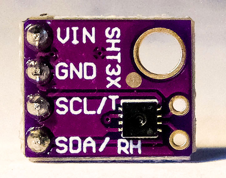
I2C mit dem ATtiny85 – SHT31 Temperatur- und Feuchtesensor
Die zweite Bibliothek, die ich modifiziert habe, ist Grove_SHT31_Temp_Humi_Sensor von Seeed Studio, Version 1.0.0. Sie dient der Ansteuerung eines SHT31 Temperatur- und Feuchtesensors.
Auch hier der Hinweis auf die Lizenz.
SHT31.h modifizieren
Die Modifikation der Headerdatei ist noch einfacher, da das Wire-Objekt bei dieser Bibliothek nicht übergeben wird. Ihr müsst in SHT31.h einfach nur #include "Wire.h" durch #include<TinyWireM.h> ersetzen.
#ifndef _SHT31_H_
#define _SHT31_H_

#include "Arduino.h"
//////// #include "Wire.h" /////// take out
#include<TinyWireM.h> /////// Add!

#define SHT31_ADDR    0x44
#define SHT31_MEAS_HIGHREP_STRETCH 0x2C06
#define SHT31_MEAS_MEDREP_STRETCH  0x2C0D
#define SHT31_MEAS_LOWREP_STRETCH  0x2C10
#define SHT31_MEAS_HIGHREP         0x2400
#define SHT31_MEAS_MEDREP          0x240B
#define SHT31_MEAS_LOWREP          0x2416
#define SHT31_READSTATUS           0xF32D
#define SHT31_CLEARSTATUS          0x3041
#define SHT31_SOFTRESET            0x30A2
#define SHT31_HEATEREN             0x306D
#define SHT31_HEATERDIS            0x3066

class SHT31 {
  public:
    SHT31();
    boolean begin(uint8_t i2caddr = SHT31_ADDR);
    float getTemperature(void);
    float getHumidity(void);
    uint16_t readStatus(void);
    void reset(void);
    void heater(boolean);
    uint8_t crc8(const uint8_t *data, int len);

  private:
    boolean getTempHum(void);
    void writeCommand(uint16_t cmd);

    uint8_t _i2caddr;
    float humidity, temp;

};

#endif
SHT31.cpp modifizieren
In SHT31.cpp ist etwas mehr zu ändern, das ist aber auch nicht kompliziert. Haltet wieder nach „Wire“ Ausschau.
#include "SHT31.h"

SHT31::SHT31() {
}

boolean SHT31::begin(uint8_t i2caddr) {
  /////// Wire.begin(); //////// Take out!!!!
  //TinyWireM.begin(); -> not necessary to put in!
  _i2caddr = i2caddr;
  reset();
  /////// return (readStatus() == 0x40); /////// Take out!!!!
  return true; //////// Add!!!!
}

float SHT31::getTemperature(void) {
  if (! getTempHum()) return NAN;
  return temp;
}


float SHT31::getHumidity(void) {
  if (! getTempHum()) return NAN;
  return humidity;
}

uint16_t SHT31::readStatus(void) {
  return 42; /////// I added this line. Without this, it compiles
             /////// with an Arduino Nano, but not with an ATtiny85
}

void SHT31::reset(void) {
  writeCommand(SHT31_SOFTRESET);
  delay(10);
}

void SHT31::heater(boolean h) {
  if (h)
    writeCommand(SHT31_HEATEREN);
  else
    writeCommand(SHT31_HEATERDIS);
}

uint8_t SHT31::crc8(const uint8_t *data, int len) {
  const uint8_t POLYNOMIAL(0x31);
  uint8_t crc(0xFF);

  for ( int j = len; j; --j ) {
      crc ^= *data++;

      for ( int i = 8; i; --i ) {
  crc = ( crc & 0x80 )
    ? (crc << 1) ^ POLYNOMIAL
    : (crc << 1);
      }
  }
  return crc;
}


boolean SHT31::getTempHum(void) {
  uint8_t readbuffer[6];

  writeCommand(SHT31_MEAS_HIGHREP);

  delay(50);
  /////// Wire.requestFrom(_i2caddr, (uint8_t)6); /////// Take out!!!!
  TinyWireM.requestFrom(_i2caddr,6); //////// Add!!!!
  //if (Wire.available() != 6) /////// Take out!!!!
  if (TinyWireM.available() != 6)
    return false;
  for (uint8_t i=0; i<6; i++) {
    //readbuffer[i] = Wire.read(); /////// Take out!!!!
  readbuffer[i] = TinyWireM.receive(); /////// Add!!!!
  }
  uint16_t ST, SRH;
  ST = readbuffer[0];
  ST <<= 8;
  ST |= readbuffer[1];

  if (readbuffer[2] != crc8(readbuffer, 2)) return false;

  SRH = readbuffer[3];
  SRH <<= 8;
  SRH |= readbuffer[4];

  if (readbuffer[5] != crc8(readbuffer+3, 2)) return false;

  double stemp = ST;
  stemp *= 175;
  stemp /= 0xffff;
  stemp = -45 + stemp;
  temp = stemp;

  double shum = SRH;
  shum *= 100;
  shum /= 0xFFFF;

  humidity = shum;

  return true;
}

void SHT31::writeCommand(uint16_t cmd) {
  /* Wire.beginTransmission(_i2caddr); /////// Take out 4 lines !!!!
  Wire.write(cmd >> 8);
  Wire.write(cmd & 0xFF);
  Wire.endTransmission();     */
  TinyWireM.beginTransmission(_i2caddr); /////// Add the following lines!!!!
  TinyWireM.send((uint8_t)(cmd >> 8));
  TinyWireM.send((uint8_t)(cmd & 0xFF));
  TinyWireM.endTransmission();
}
Sketch sht31
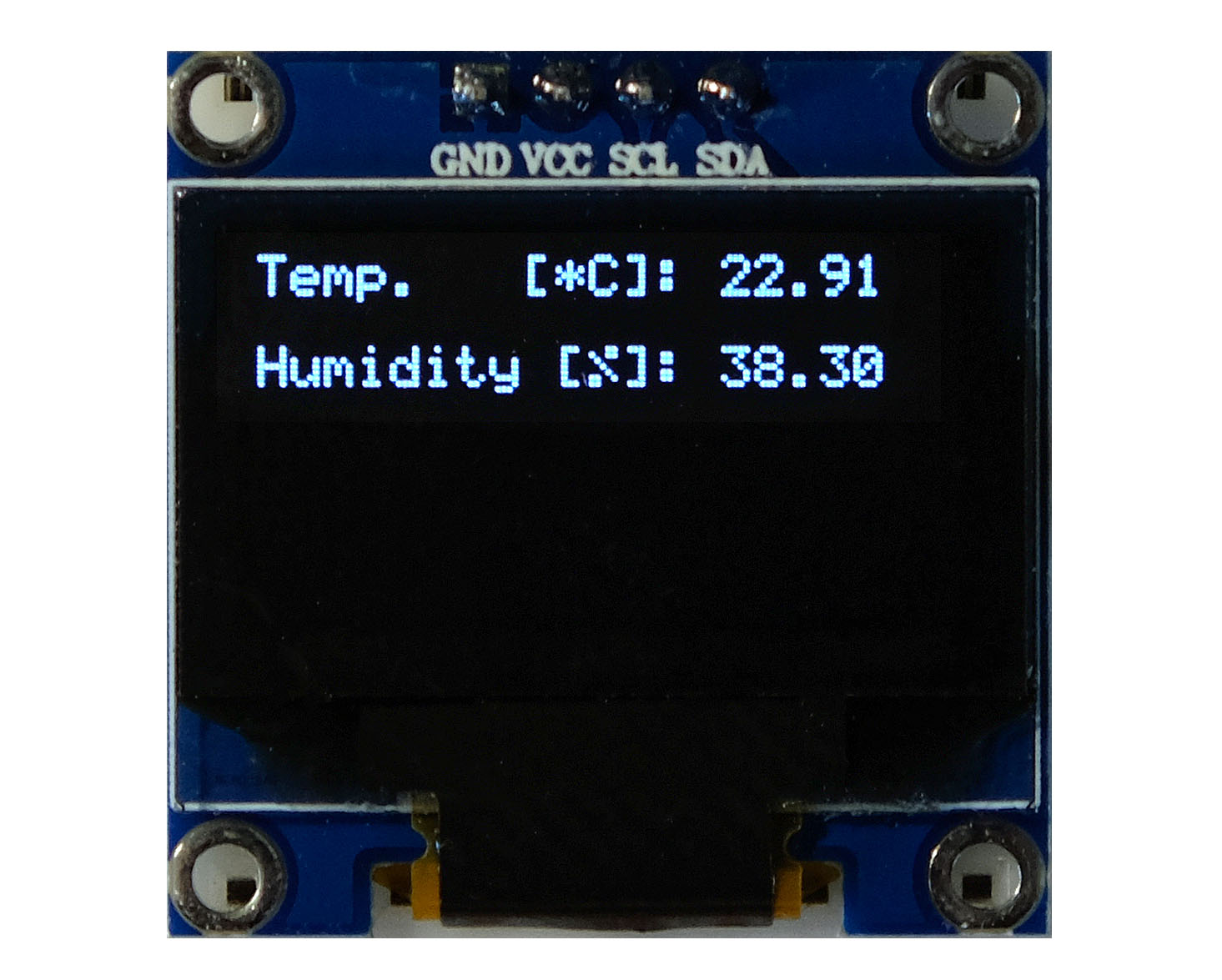
Dann ist noch ein Test-Sketch zu erstellen, was nicht schwierig ist. Dazu sucht ihr euch einfach die relevanten Funktionen aus dem Beispielsketch. Das Ergebnis könnte dann so aussehen:
#include <TinyWireM.h>
#include <Tiny4kOLED.h>
#include <SHT31.h>

uint8_t width = 128;
uint8_t height = 64;

SHT31 sht31 = SHT31();

void setup() {
  TinyWireM.begin();
  oled.begin(width, height, sizeof(tiny4koled_init_128x64br), tiny4koled_init_128x64br);
  oled.setFont(FONT6X8);
  oled.clear();
  oled.on();

  oled.setCursor(0, 0);
  sht31.begin();
  sht31.heater(false); // heater off, with "true" it's on -> can remove condensated water,
                       // but gives false temperature values (about 3 degrees too high);
}

void loop() {
  float temp = sht31.getTemperature();
  float hum = sht31.getHumidity();

  oled.setCursor(0,0);
  oled.print("Temp.   [*C]: ");
  oled.print(temp);
  oled.clearToEOL();

  oled.setCursor(0,2); //10
  oled.print("Humidity [%]: ");
  oled.print(hum);
  oled.clearToEOL();

  delay(2000);
}
Dieser Sketch benötigt übrigens nur 62 % des Programmspeichers. Und hier noch die Ausgabe:
Danksagung
Ich danke den Autoren der Bibliotheken TinyWireM, Tiny4kOLED, MPU6050_light und Grove_SHT31_Temp_Humi_Sensor.
Hallo Wolfgang,
dass die Wire-Bibliothek nicht so gut für AtTiny85s ist habe ich auch inzwischen leidvoll erfahren. Hast Du eine aktuelle Empfehlung für eine Library, wenn ich den AtTiny85 als Slave einsetzen will. Ich habe jetzt (noch nicht intensiv) ein paar Bibliotheken durchprobiert, aber ohne echten Erfolg.
Vielen Dank für Deine wertvollen Artikel. Haben mir schon oft geholfen oder auf die richtige Spur gesetzt.
Liebe Grüße
Jan
Hallo Jan,
hast du mal diese TinyWireS (S für „Slave“) probiert?
https://github.com/nadavmatalon/TinyWireS
Selbst ausprobiert habe ich sie allerdings nicht.
Und danke für dein generelles Feedback!
VG, Wolfgang
Hallo Wolfgang, erst mal vielen Dank für diesen klasse Beitrag !
Habe nur eine Frage zu den LED BAR’s . Könntest Du mir sage wo diese zu beziehen sind. Einfarbige hab ich bei Aliexpress gefunden aber keine die wie die in Deinem Beitrag mehrere Farben haben.
Grüße
Frank
Hi Frank,
z.B. hier: https://de.aliexpress.com/item/32273964628.html
und hier:
https://de.aliexpress.com/item/32909606852.html
VG, Wolfgang
Hallo Wolfgang,
vielen Dank für Deine schnelle Hilfe/Info.
Habe wohl etwas falsch gesucht. Auf jeden Fall hab ich mir gleich verschiedene Ausführungen bestellt.
Auch der Artikel über den Portexpander ist wirklich super!
VG Frank
Hallo Wolfgang,
ich habe die Lib nach deiner Anleitung modifiziert und bekomme vom Compiler folgende Meldung:
D:\Apps\Arduino-1.8.19 Portable\portable\sketchbook\libraries\Grove_SHT31_Temp_Humi_Sensor-master\SHT31.cpp:15:7: error: prototype for ‚float SHT31::getTemperature()‘ does not match any in class ‚SHT31‘
float SHT31::getTemperature(void) {
^~~~~
In file included from D:\Apps\Arduino-1.8.19 Portable\portable\sketchbook\libraries\Grove_SHT31_Temp_Humi_Sensor-master\SHT31.cpp:1:0:
D:\Apps\Arduino-1.8.19 Portable\portable\sketchbook\libraries\Grove_SHT31_Temp_Humi_Sensor-master\SHT31.h:24:11: error: candidate is: float SHT31::getTemperature(bool)
float getTemperature(bool S = false);
^~~~~~~~~~~~~~
D:\Apps\Arduino-1.8.19 Portable\portable\sketchbook\libraries\Grove_SHT31_Temp_Humi_Sensor-master\SHT31.cpp:26:32: error: no ‚uint16_t SHT31::readStatus()‘ member function declared in class ‚SHT31‘
uint16_t SHT31::readStatus(void) {
Ich kann mir das nicht erklären, um ein ratschlag wäre ich sehr dankbar. Ich habe deinen Beilspielsketch verwendet
Hi, ich schätze, du hast die Bibliothek manuell installiert und nicht über den Library Manager. Das sollte normalerweise keinen Unterschied machen, hier aber schon. Die Macher der Bibliothek haben auf GitHub eine Version 1.0.1 veröffentlicht, aber in der Datei library.properties vergessen die Versionsnummer hochzusetzen. Das ist aber wichtig für die Arduino IDE. Über die Arduino IDE installierst du derzeit die Version 1.0.0 Wenn jetzt meine Version der SHT31.cpp nimmst (basierend auf der Version 1.0.0) und mit der SHT31.h der Version 1.0.1 kombinierst, dann funktioniert es nicht mehr. Die Fehlermeldungen passen zu den Unterschieden.
Lange Rede, kurzer Sinn: ich habe jetzt auch die passende Version der SHT31.h mit in den Beitrag aufgenommen. Damit geht es. Wenn du lieber die Version 1.0.1 verwenden möchtest, dann müsstest du die Änderungen sinngemäß übertragen.
VG, Wolfgang
Hallo Wolfgang,
danke für Deinen lehrreichen Beitrag.
Bzgl. I2C: kennst Du von David Johnson die Routinen, die ohne Puffer arbeiten und sehr sparsam mit dem RAM umgehen:
http://www.technoblogy.com/show?3UF0
beste Grüße
Vielen Dank dafür! Das schaue ich mir demnächst mal an.
Hallo Wolfgang,
wie immer ein toller und hilfreicher Artikel !
Meine Frage: Da im Sketch keine Adresse für das Display anzugeben ist, ist diese dann fest in derTiny4kOLED- Bibliothek hinterlegt und wenn ja, kann man die Adresse dann trotzdem irgendwie ändern ?
Grüße
Alex
Hallo Alex,
man muss es tatsächlich in einer der Bibliotheksdateien ändern. Das hat natürlich den Nachteil, dass deine Änderung bei einem Update der Bibliothek überschrieben wird. Die Definition der I2C Adresse findet sich in der Datei Tiny4kOLED_common.h, Zeile 62. 0x3C ist vordefiniert.
Die andere Frage ist, wie man die I2C Adresse am Display ändert. Einige Displays habe die Änderung vorgesehen, andere nicht.
Bei diesem hier geht es:
https://www.joy-it.net/files/files/Produkte/SBC-OLED01/SBC-OLED01_Anleitung_2022-01-06.pdf
VG, Wolfgang