About this post
The MPU6050, or more precisely the module based on it, is a 3-axis accelerometer and 3-axis gyroscope. In addition, the MPU6050 measures the temperature. A lot has already been written about this sensor, but maybe I can give you one or the other new aspect with this post, like the interrupt programming.
The post is structured as follows:
If you just want to get started quickly, you can go directly to the libraries.
Basics
The measuring principle of the MPU6050
In the context of accelerometers, you often come across the terms “3-axis”, “6-axis” or even “9-axis sensors”. Don’t worry, we are not leaving the three-dimensional world. Instead, one or more sensors, which are effective in three dimensions, are used in parallel. And in the case of the MPU6050, this is an accelerometer and a gyroscope. 9-axis sensors usually have an additional geomagnetic field sensor.
Gyroscopes
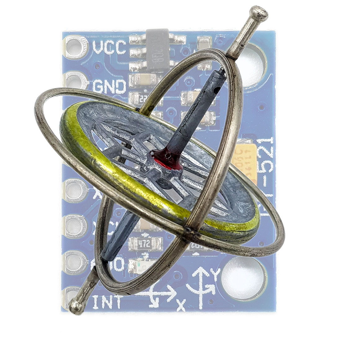
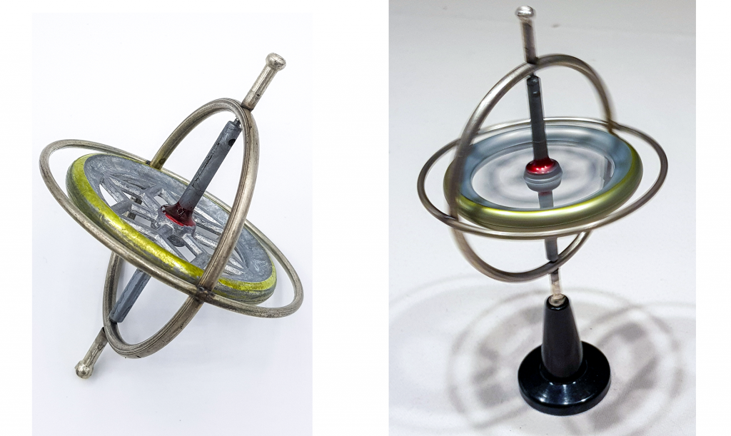
The classical gyroscope works like a toy whipping top. Everyone knows it from childhood and also its effect. The rotation stabilizes it (precession) and therefore the attempt to tilt its axis of rotation requires force. And exactly with this, you can determine the inclination or angular acceleration of an object (e.g. an airplane or ship). Compared to the simple whipping tops, the gyroscope is mounted in a frame. An exemplary toy gyroscope:
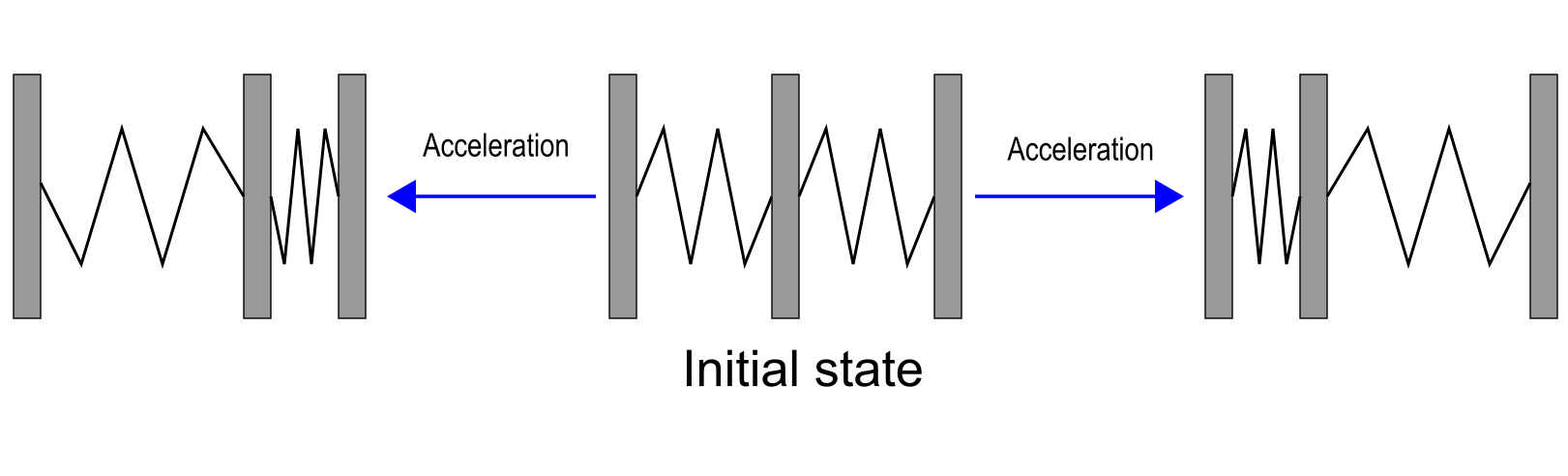
In the MPU6050 there is of course no part which is spinning (and fortunately, you don’t have to move it manually ;-)). Such sensors are based on”Micro-Electric-Mechanical Systems” (MEMS). In the case of gyroscopes, these are moving parts that change their position within a fixed frame when accelerated. The distance change results in a change in capacity. In principle, this is how it looks:
An older technique is based on the piezo effect, so it uses pressure changes as the measuring principle.
Accelerometers
An accelerometer works according to the same principle. The difference is that the accelerometer detects acceleration in the x-, y-, and z-axis directions, while the gyroscope detects motion about the axes. When the module is in the idle state, the gyroscope returns zero for x, y and z. The acceleration sensor, on the other hand, detects the acceleration due to gravity even at rest (in the z-direction when the module is flat).
The modules have printed the position of the x- and y-axis. The z-axis is the perpendicular on the module.

Technical Data / Features
The most important technical data of the MPU6050 are:
- Power supply (VDD/GND): the module has an LDO voltage converter (see also here), and hence it can be supplied with 3.3 volts as well as with 5 volts.
- Power consumption(module): approx. 5.1 mA, in sleep mode approx. 1.4 mA (own measurements). If you remove the LED, the consumption is reduced to 3.7 mA or 33 µA in sleep mode.
- Accelerometer: 16-bit resolution, measuring ranges +/- 2, 4, 8 or 16 g; with g = earth acceleration, not grams!
- Gyroscope: 16-bit resolution, measuring ranges: +/- 250, 500, 1000 or 2000°/s.
- Communication (SDA/SCL): I2C, address 0x68 (AD0 = GND or unconnected) or 0x69 (AD0 = HIGH)
- Interrupts: data ready, free fall, acceleration limit;
- Connection of additional sensors (XDA / XCL): I will not go into this.
For more information, see the data sheet and the register map.
Control of the MPU6050 without library
The minimal sketch
If you can live with the defaults (+/-2 g, +/-250°/s), then you might get by with the following sketch (based on: Arduino Playground).
I’m not going to go through all the details of the sketch, just so much:
- First, the MPU6050 is awakened by the entry of a zero in the “Power Management 1” register.
- The MPU6050 continuously produces results for acceleration, gyroscope and temperature.
- Since the result registers are sequential, they can be read out conveniently in one go.
- Only raw data is output (-32767 to + 32767).
#include "Wire.h"

#define MPU6050_ADDR 0x68 // Alternatively set AD0 to HIGH  --> Address = 0x69

int16_t accX, accY, accZ, gyroX, gyroY, gyroZ, tRaw; // Raw register values (accelaration, gyroscope, temperature)
char result[7]; // temporary variable used in convert function

void setup() {
  Serial.begin(9600);
  Wire.begin();
  Wire.beginTransmission(MPU6050_ADDR);
  Wire.write(0x6B); // PWR_MGMT_1 register
  Wire.write(0); // wake up!
  Wire.endTransmission(true);
}
void loop() {
  Wire.beginTransmission(MPU6050_ADDR);
  Wire.write(0x3B); // starting with register 0x3B (ACCEL_XOUT_H)
  Wire.endTransmission(false); // the parameter indicates that the Arduino will send a restart.
                               // As a result, the connection is kept active.
  Wire.requestFrom(MPU6050_ADDR, 14, true); // request a total of 7*2=14 registers

  // "Wire.read()<<8 | Wire.read();" means two registers are read and stored in the same int16_t variable
  accX = Wire.read()<<8 | Wire.read(); // reading registers: 0x3B (ACCEL_XOUT_H) and 0x3C (ACCEL_XOUT_L)
  accY = Wire.read()<<8 | Wire.read(); // reading registers: 0x3D (ACCEL_YOUT_H) and 0x3E (ACCEL_YOUT_L)
  accZ = Wire.read()<<8 | Wire.read(); // reading registers: 0x3F (ACCEL_ZOUT_H) and 0x40 (ACCEL_ZOUT_L)
  tRaw = Wire.read()<<8 | Wire.read(); // reading registers: 0x41 (TEMP_OUT_H) and 0x42 (TEMP_OUT_L)
  gyroX = Wire.read()<<8 | Wire.read(); // reading registers: 0x43 (GYRO_XOUT_H) and 0x44 (GYRO_XOUT_L)
  gyroY = Wire.read()<<8 | Wire.read(); // reading registers: 0x45 (GYRO_YOUT_H) and 0x46 (GYRO_YOUT_L)
  gyroZ = Wire.read()<<8 | Wire.read(); // reading registers: 0x47 (GYRO_ZOUT_H) and 0x48 (GYRO_ZOUT_L)

  Serial.print("AcX = "); Serial.print(toStr(accX));
  Serial.print(" | AcY = "); Serial.print(toStr(accY));
  Serial.print(" | AcZ = "); Serial.print(toStr(accZ));
  // from data sheet:
  Serial.print(" | tmp = "); Serial.print((tRaw + 12412.0) / 340.0);
  Serial.print(" | GyX = "); Serial.print(toStr(gyroX));
  Serial.print(" | GyY = "); Serial.print(toStr(gyroY));
  Serial.print(" | GyZ = "); Serial.print(toStr(gyroZ));
  Serial.println();

  delay(1000);
}

char* toStr(int16_t character) { // converts int16 to string and formatting
  sprintf(result, "%6d", character);
  return result;
}
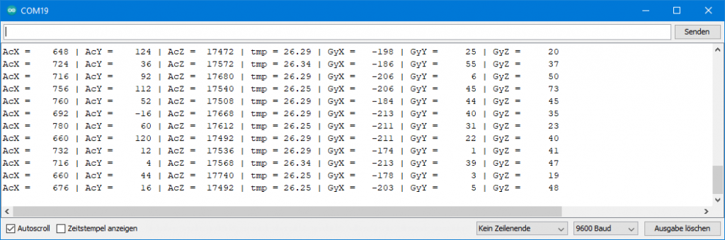
Below you can see the output of the sketch on the serial monitor. Since the MPU6050 was placed flat in the x/y plane, all results except acceleration in the z-direction (acceleration due to gravity) should be zero. This is not the case, but the result is not bad in first approximation.
You can adjust the initial values by entering offset values in corresponding registers. Some libraries have implemented this option, others have not.
For completeness, I have shown the circuit here. We will need the LED and the line to the interrupt later. Pull-ups for the I2C lines (3.3 V) are integrated on the module.

The extended Minimalsketch
I then added a few extras to the minimum sketch:
setAccRange()sets the measuring range for acceleration.setGyrRange()sets the measuring range for the gyroscope.MCP6050_wakeUp()awakens the MPU6050.- It needs some time to wake up, only after 30 ms I could determine meaningful gyroscope values.
MCP6050_sleepsends the MPU6050 to sleep.
By applying intermittent sleep, I could reduce the power consumption from 5.2 to 1.4 mA with the following sketch. If you then remove the LED, the consumption drops to less than 0.1 mA.
If you want to understand the sketch in terms of register settings, take a look at the register map.
#include "Wire.h"

#define MPU6050_ADDR              0x68 // Alternatively set AD0 to HIGH  --> Address = 0x69
#define MPU6050_GYRO_CONFIG       0x1B ///< Gyro specfic configuration register
#define MPU6050_ACCEL_CONFIG      0x1C
#define MPU6050_ACCEL_XOUT_H      0x3B
#define MPU6050_PWR_MGT_1         0x6B
#define MPU6050_SLEEP             0x06

typedef enum {
  MPU6050_ACC_RANGE_2G,  // +/- 2g (default)
  MPU6050_ACC_RANGE_4G,  // +/- 4g
  MPU6050_ACC_RANGE_8G,  // +/- 8g
  MPU6050_ACC_RANGE_16G // +/- 16g
} mpu6050_acc_range;

typedef enum {
  MPU6050_GYR_RANGE_250,  // +/- 250 deg/s (default)
  MPU6050_GYR_RANGE_500,  // +/- 500 deg/s
  MPU6050_GYR_RANGE_1000, // +/- 1000 deg/s
  MPU6050_GYR_RANGE_2000  // +/- 2000 deg/s
} mpu6050_gyr_range;

int16_t accX, accY, accZ, gyroX, gyroY, gyroZ, tRaw; // Raw register values (accelaration, gyroscope, temperature)
char result[7];

void setup() {
  Serial.begin(9600);
  Wire.begin();
  MPU6050_wakeUp();
  setAccRange(MPU6050_ACC_RANGE_16G);
  setGyrRange(MPU6050_GYR_RANGE_250);
}

void loop() {
  MPU6050_wakeUp();
  Wire.beginTransmission(MPU6050_ADDR);
  Wire.write(MPU6050_ACCEL_XOUT_H); // starting with register ACCEL_XOUT_H
  Wire.endTransmission(false); // the parameter indicates that the Arduino will send a restart.
                               // As a result, the connection is kept active.
  Wire.requestFrom(MPU6050_ADDR, 7*2, true); // request a total of 7*2=14 registers

  // "Wire.read()<<8 | Wire.read();" means two registers are read and stored in the same variable
  accX = Wire.read()<<8 | Wire.read(); // reading registers: 0x3B (ACCEL_XOUT_H) and 0x3C (ACCEL_XOUT_L)
  accY = Wire.read()<<8 | Wire.read(); // reading registers: 0x3D (ACCEL_YOUT_H) and 0x3E (ACCEL_YOUT_L)
  accZ = Wire.read()<<8 | Wire.read(); // reading registers: 0x3F (ACCEL_ZOUT_H) and 0x40 (ACCEL_ZOUT_L)
  tRaw = Wire.read()<<8 | Wire.read(); // reading registers: 0x41 (TEMP_OUT_H) and 0x42 (TEMP_OUT_L)
  gyroX = Wire.read()<<8 | Wire.read(); // reading registers: 0x43 (GYRO_XOUT_H) and 0x44 (GYRO_XOUT_L)
  gyroY = Wire.read()<<8 | Wire.read(); // reading registers: 0x45 (GYRO_YOUT_H) and 0x46 (GYRO_YOUT_L)
  gyroZ = Wire.read()<<8 | Wire.read(); // reading registers: 0x47 (GYRO_ZOUT_H) and 0x48 (GYRO_ZOUT_L)
  MPU6050_sleep();

  // print out data
  Serial.print("AcX = "); Serial.print(toStr(accX));
  Serial.print(" | AcY = "); Serial.print(toStr(accY));
  Serial.print(" | AcZ = "); Serial.print(toStr(accZ));
  // the following equation was taken from the documentation [MPU-6000/MPU-6050 Register Map and Description, p.30]
  Serial.print(" | tmp = "); Serial.print((tRaw + 12412.0) / 340.0);
  Serial.print(" | GyX = "); Serial.print(toStr(gyroX));
  Serial.print(" | GyY = "); Serial.print(toStr(gyroY));
  Serial.print(" | GyZ = "); Serial.print(toStr(gyroZ));
  Serial.println();

  delay(1000);
}

char* toStr(int16_t i) { // int16 to string plus output format
  sprintf(result, "%6d", i);
  return result;
}

void setAccRange(mpu6050_acc_range range){
  writeRegister(MPU6050_ACCEL_CONFIG, range<<3);
}

void setGyrRange(mpu6050_gyr_range range){
  writeRegister(MPU6050_GYRO_CONFIG, range<<3);
}

void MPU6050_wakeUp(){
  writeRegister(MPU6050_PWR_MGT_1, 0);
  delay(30); // give him time to wake up, gyro needs quite a while to stabilize;
}

void MPU6050_sleep(){
  writeRegister(MPU6050_PWR_MGT_1, 1<<MPU6050_SLEEP);
}

void writeRegister(uint16_t reg, byte value){
  Wire.beginTransmission(MPU6050_ADDR);
  Wire.write(reg);
  Wire.write(value);
  Wire.endTransmission(true);
}
Since I have chosen the range +/- 16 g in the example, the measured values for the acceleration in z-direction decrease to one eighth:

I could have added more features, but at some point it gets confusing and then libraries are the better choice.
Conversion of raw data
For the conversion of the raw values to values in g, the following applies:
![\[ \text{g-value}\;[\text{g}]=\frac{\vert range \vert\cdot rawV\!alue}{32768} \]](https://wolles-elektronikkiste.de/wp-content/ql-cache/quicklatex.com-604abe755f7b921d1d4a6bcab33a5532_l3.png "Rendered by QuickLaTeX.com")
The conversion of the gyroscope data into angular velocities is done according to the following formula (derived from the data sheet):
![\[ \omega\;[\text{°\!/s}] = \frac{\vert range \vert\ \cdot rawV\!alue}{131\cdot 250} \]](https://wolles-elektronikkiste.de/wp-content/ql-cache/quicklatex.com-ada29571dea7903a365066d28181591b_l3.png "Rendered by QuickLaTeX.com")
Interrupts
Perhaps the following very short video of the “Magic Push Button” will whet your appetite for the interrupt function, which by the way was not implemented in any library I looked at.
As you can see, a press on the button makes the LED glow – even though the button is not connected at all. The solution to the puzzle is that the vibration when the pushbutton is pressed is sufficient to trigger a correspondingly sensitive “wake on motion” interrupt. So, I could just as easily have knocked on the table. The Arduino sketch ensures that when the interrupt is registered, the LED lights up for one second.
You can also do other great things with this interrupt. For example, you can build a device that turns itself on when you pick it up. If it’s lying around, it should be sleeping. No problem, you only have to use the interrupt signal as a wake-up signal for the microcontroller. See also my article about Sleep Modes.
The problem with undocumented registers
The datasheet of the MPU6050 describes a procedure for setting up interrupts. The problem is that it doesn’t work. While searching the net, I came across this page, that explains how to do it right. Both undocumented registers in the data sheet and undocumented bits of documented registers are used.
Interestingly, there are hardworking people who have done the documentation work for the registers in a reverse engineering process. The result, i.e. the complete register map, can be found here.
The Interrupt Sketch
I took the instructions and wrote the following sketch based on it. Some steps suggested in the manual are not necessary in my opinion. I inserted but commented them.
Explaining the sketch in detail would be beyond the scope. Just a few comments:
setInterrupt(x)activates the interrupt; x sets sensitivity to a value between 1 (4 mg = “4 milli-g”, not milligrams) and 255 (1024 mg)- at 255 you have to shake the MPU6050 vigorously to trigger the interrupt
- if you want to set the interrupt pin active-low, then uncomment line 41
- using the latch function you can set the interrupt pin to remain active until the next read. To do this, change line 41 to:
writeRegister(MPU6050_INT_PIN_CFG, 1<<MPU6050_LATCH_INT_EN) - Combination of active-low and latch:
writeRegister(MPU6050_INT_PIN_CFG, ((1<<MPU6050_ACTL) | (1<<MPU6050_LATCH_IN_EN))
Here’s the sketch:
#include "Wire.h"

#define MPU6050_ADDR              0x68 // Alternatively set AD0 to HIGH  --> Address = 0x69
#define MPU6050_ACCEL_CONFIG      0x1C // Accelerometer Configuration Register
#define MPU6050_PWR_MGT_1         0x6B // Power Management 1 Register
#define MPU6050_INT_PIN_CFG       0x37 // Interrupt Pin / Bypass Enable Configuration Register
#define MPU6050_INT_ENABLE        0x38 // Interrupt Enable Register
#define MPU6050_LATCH_INT_EN      0x05 // Latch Enable Bit for Interrupt
#define MPU6050_ACTL              0x07 // Active-Low Enable Bit
#define MPU6050_WOM_EN            0x06 // Wake on Motion Enable bit
#define MPU6050_WOM_THR           0x1F // Wake on Motion Threshold Register
#define MPU6050_MOT_DUR           0x20 // Motion Detection Duration Register
#define MPU6050_ACCEL_INTEL_CTRL  0x69 // Accelaration Interrupt Control Register
#define MPU6050_SIGNAL_PATH_RESET 0x68 // Signal Path Reset Register

byte interruptPin=2;
byte ledPin=10;
volatile bool accEvent = false;

void setup() {
  Wire.begin();
  writeRegister(MPU6050_PWR_MGT_1, 0);
  setInterrupt(1); // set Wake on Motion Interrupt / Sensitivity; 1(highest sensitivity) - 255
  pinMode(ledPin, OUTPUT);
  pinMode(interruptPin, INPUT);
  attachInterrupt(digitalPinToInterrupt(interruptPin), motion, RISING);
}

void loop() {
   if(accEvent){
    digitalWrite(ledPin, HIGH);
    delay(1000);
    digitalWrite(ledPin, LOW);
    accEvent = false;
    attachInterrupt(digitalPinToInterrupt(interruptPin), motion, RISING);
  }
}

void setInterrupt(byte threshold){
//writeRegister(MPU6050_SIGNAL_PATH_RESET, 0b00000111);  // not(?) needed
//writeRegister(MPU6050_INT_PIN_CFG, 1<<MPU6050_ACTL); // 1<<MPU6050_LATCH_INT_EN
  writeRegister(MPU6050_ACCEL_CONFIG, 0b00000001);
  writeRegister(MPU6050_WOM_THR, threshold);
  writeRegister(MPU6050_MOT_DUR, 0b00000001);  // set duration (LSB = 1 ms)
//writeRegister(MPU6050_ACCEL_INTEL_CTRL, 0x15);  // not needed (?)
  writeRegister(MPU6050_INT_ENABLE, 1<<MPU6050_WOM_EN);
}

void writeRegister(uint16_t reg, byte value){
  Wire.beginTransmission(MPU6050_ADDR);
  Wire.write(reg);
  Wire.write(value);
  Wire.endTransmission();
}

void motion(){
  accEvent = true;
  detachInterrupt(digitalPinToInterrupt(interruptPin));
}
Libraries for the MPU6050
No library I have found really takes full advantage of the features of the MPU6050. The interrupts are just an example. I would like to create a more complete library. However, the effort is considerable and most of you are likely to get along with the basic features. Maybe I will come back to that.
Adafruit MPU6050
The most complete library I have found is that of Adafruit. You can download it directly from GitHub here or install it via the library manager in the Arduino IDE.
Basic reading sketch
The best way to start is with the included sample basic_readings.ino. It reads the acceleration, temperature and gyroscope values. You can set the measuring ranges and a low-pass filter (setFilterBandwith()) for the sensors. I will come to the filter below. Here’s the unchanged sketch:
// Basic demo for accelerometer readings from Adafruit MPU6050

#include <Adafruit_MPU6050.h>
#include <Adafruit_Sensor.h>
#include <Wire.h>

Adafruit_MPU6050 mpu;

void setup(void) {
  Serial.begin(115200);
  while (!Serial)
    delay(10); // will pause Zero, Leonardo, etc until serial console opens

  Serial.println("Adafruit MPU6050 test!");

  // Try to initialize!
  if (!mpu.begin()) {
    Serial.println("Failed to find MPU6050 chip");
    while (1) {
      delay(10);
    }
  }
  Serial.println("MPU6050 Found!");

  mpu.setAccelerometerRange(MPU6050_RANGE_8_G);
  Serial.print("Accelerometer range set to: ");
  switch (mpu.getAccelerometerRange()) {
  case MPU6050_RANGE_2_G:
    Serial.println("+-2G");
    break;
  case MPU6050_RANGE_4_G:
    Serial.println("+-4G");
    break;
  case MPU6050_RANGE_8_G:
    Serial.println("+-8G");
    break;
  case MPU6050_RANGE_16_G:
    Serial.println("+-16G");
    break;
  }
  mpu.setGyroRange(MPU6050_RANGE_500_DEG);
  Serial.print("Gyro range set to: ");
  switch (mpu.getGyroRange()) {
  case MPU6050_RANGE_250_DEG:
    Serial.println("+- 250 deg/s");
    break;
  case MPU6050_RANGE_500_DEG:
    Serial.println("+- 500 deg/s");
    break;
  case MPU6050_RANGE_1000_DEG:
    Serial.println("+- 1000 deg/s");
    break;
  case MPU6050_RANGE_2000_DEG:
    Serial.println("+- 2000 deg/s");
    break;
  }

  mpu.setFilterBandwidth(MPU6050_BAND_21_HZ);
  Serial.print("Filter bandwidth set to: ");
  switch (mpu.getFilterBandwidth()) {
  case MPU6050_BAND_260_HZ:
    Serial.println("260 Hz");
    break;
  case MPU6050_BAND_184_HZ:
    Serial.println("184 Hz");
    break;
  case MPU6050_BAND_94_HZ:
    Serial.println("94 Hz");
    break;
  case MPU6050_BAND_44_HZ:
    Serial.println("44 Hz");
    break;
  case MPU6050_BAND_21_HZ:
    Serial.println("21 Hz");
    break;
  case MPU6050_BAND_10_HZ:
    Serial.println("10 Hz");
    break;
  case MPU6050_BAND_5_HZ:
    Serial.println("5 Hz");
    break;
  }

  Serial.println("");
  delay(100);
}

void loop() {

  /* Get new sensor events with the readings */
  sensors_event_t a, g, temp;
  mpu.getEvent(&a, &g, &temp);

  /* Print out the values */
  Serial.print("Acceleration X: ");
  Serial.print(a.acceleration.x);
  Serial.print(", Y: ");
  Serial.print(a.acceleration.y);
  Serial.print(", Z: ");
  Serial.print(a.acceleration.z);
  Serial.println(" m/s^2");

  Serial.print("Rotation X: ");
  Serial.print(g.gyro.x);
  Serial.print(", Y: ");
  Serial.print(g.gyro.y);
  Serial.print(", Z: ");
  Serial.print(g.gyro.z);
  Serial.println(" rad/s");

  Serial.print("Temperature: ");
  Serial.print(temp.temperature);
  Serial.println(" degC");

  Serial.println("");
  delay(500);
}
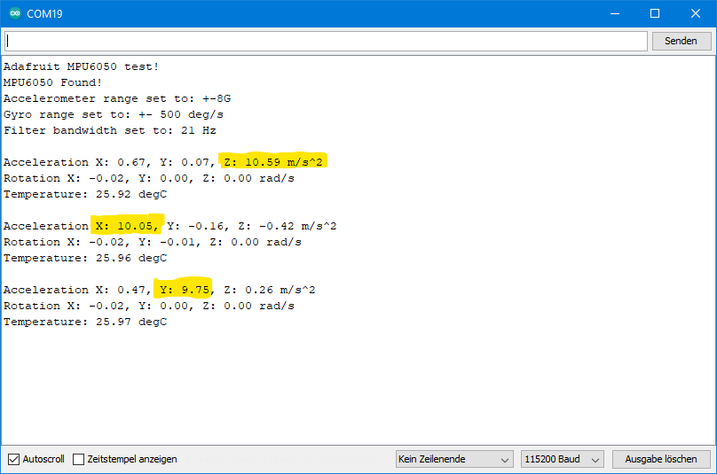
Note that the results are output in m/s2 or rad/s. Here I positioned the module in three different ways: 1) z-axis in the direction of the vertical, 2) x-axis in the direction of the vertical and finally 3) y-axis in the direction of the vertical.
If you want to convert angular velocities to degrees/s:
![\[ 2\pi\cdot rad = 360° \;\; \Rightarrow\;\;1°=\frac{2\pi\cdot rad}{360} \]](https://wolles-elektronikkiste.de/wp-content/ql-cache/quicklatex.com-8942e52bf22b09ae79ed86698255f2c7_l3.png "Rendered by QuickLaTeX.com")
For the conversion of the acceleration values to g, divide the values by 9.81.
Plotter Sketch
Especially with angular velocities, you may not only want to determine individual values, but also track the progression. The sketch plotter.ino is suitable for this purpose, which I also print here unchanged:
// Basic demo for accelerometer readings from Adafruit MPU6050

#include <Adafruit_MPU6050.h>
#include <Adafruit_Sensor.h>
#include <Wire.h>

Adafruit_MPU6050 mpu;

void setup(void) {
  Serial.begin(115200);
  while (!Serial) {
    delay(10); // will pause Zero, Leonardo, etc until serial console opens
  }

  // Try to initialize!
  if (!mpu.begin()) {
    Serial.println("Failed to find MPU6050 chip");
    while (1) {
      delay(10);
    }
  }

  mpu.setAccelerometerRange(MPU6050_RANGE_16_G);
  mpu.setGyroRange(MPU6050_RANGE_250_DEG);
  mpu.setFilterBandwidth(MPU6050_BAND_21_HZ);
  Serial.println("");
  delay(100);
}

void loop() {

  /* Get new sensor events with the readings */
  sensors_event_t a, g, temp;
  mpu.getEvent(&a, &g, &temp);

  /* Print out the values */
  Serial.print(a.acceleration.x);
  Serial.print(",");
  Serial.print(a.acceleration.y);
  Serial.print(",");
  Serial.print(a.acceleration.z);
  Serial.print(", ");
  Serial.print(g.gyro.x);
  Serial.print(",");
  Serial.print(g.gyro.y);
  Serial.print(",");
  Serial.print(g.gyro.z);
  Serial.println("");

  delay(10);
}
Upload the sketch and then select the serial plotter instead of the serial monitor. Here I turned the MPU6050 several times by 90°. The gyroscope peaks are the small pink and orange peaks between the bigger accelerometer peaks:

Cycle and Filter Bandwith
I would like to mention two parameters whose effect is illustrated by the following sketch. This sketch is from me, so it’s not part of the library’s sample sketch.
The function setCycleRate(frequency) causes the MPU6050 to go to sleep and wake up at the specified frequency to record a set of readings. This saves considerable power. Strictly speaking, the function only sets the frequency. It is activated with enableCycle(true). If you pass “false”, it becomes inactive.
The function setFilterBandwith(bandwith) dampens the fluctuation of the measured value. If you upload the sketch with the parameters I have selected (see line 58/84) and tilt your MPU6050, you will see that the readings are very sluggish. If you use the cycle function, you should set the bandwidth high. For example, change the value to 260 Hz and see what happens.
// Basic demo for cycle and filter bandwith from Adafruit MPU6050

#include <Adafruit_MPU6050.h>
#include <Adafruit_Sensor.h>
#include <Wire.h>

Adafruit_MPU6050 mpu;

void setup(void) {
  Serial.begin(115200);
  while (!Serial)
    delay(10); // will pause Zero, Leonardo, etc until serial console opens

  Serial.println("Adafruit MPU6050 test!");

  // Try to initialize!
  if (!mpu.begin()) {
    Serial.println("Failed to find MPU6050 chip");
    while (1) {
      delay(10);
    }
  }
  Serial.println("MPU6050 Found!");

  mpu.setAccelerometerRange(MPU6050_RANGE_8_G);
  Serial.print("Accelerometer range set to: ");
  switch (mpu.getAccelerometerRange()) {
  case MPU6050_RANGE_2_G:
    Serial.println("+-2G");
    break;
  case MPU6050_RANGE_4_G:
    Serial.println("+-4G");
    break;
  case MPU6050_RANGE_8_G:
    Serial.println("+-8G");
    break;
  case MPU6050_RANGE_16_G:
    Serial.println("+-16G");
    break;
  }
  mpu.setGyroRange(MPU6050_RANGE_500_DEG);
  Serial.print("Gyro range set to: ");
  switch (mpu.getGyroRange()) {
  case MPU6050_RANGE_250_DEG:
    Serial.println("+- 250 deg/s");
    break;
  case MPU6050_RANGE_500_DEG:
    Serial.println("+- 500 deg/s");
    break;
  case MPU6050_RANGE_1000_DEG:
    Serial.println("+- 1000 deg/s");
    break;
  case MPU6050_RANGE_2000_DEG:
    Serial.println("+- 2000 deg/s");
    break;
  }

  mpu.setFilterBandwidth(MPU6050_BAND_10_HZ);
  Serial.print("Filter bandwidth set to: ");
  switch (mpu.getFilterBandwidth()) {
  case MPU6050_BAND_260_HZ:
    Serial.println("260 Hz");
    break;
  case MPU6050_BAND_184_HZ:
    Serial.println("184 Hz");
    break;
  case MPU6050_BAND_94_HZ:
    Serial.println("94 Hz");
    break;
  case MPU6050_BAND_44_HZ:
    Serial.println("44 Hz");
    break;
  case MPU6050_BAND_21_HZ:
    Serial.println("21 Hz");
    break;
  case MPU6050_BAND_10_HZ:
    Serial.println("10 Hz");
    break;
  case MPU6050_BAND_5_HZ:
    Serial.println("5 Hz");
    break;
  }

  mpu.setCycleRate(MPU6050_CYCLE_5_HZ);
  Serial.print("Cycle rate set to: ");
  switch (mpu.getCycleRate()) {
  case MPU6050_CYCLE_1_25_HZ:
    Serial.println("1.25 Hz");
    break;
  case MPU6050_CYCLE_5_HZ:
    Serial.println("5 Hz");
    break;
  case MPU6050_CYCLE_20_HZ:
    Serial.println("20 Hz");
    break;
  case MPU6050_CYCLE_40_HZ:
    Serial.println("40 Hz");
    break;
  }

  mpu.enableCycle(true);

  Serial.println("");
  delay(100);
}

void loop() {

  /* Get new sensor events with the readings */
  sensors_event_t a, g, temp;
  mpu.getEvent(&a, &g, &temp);

  /* Print out the values */
  Serial.print("Acceleration X: ");
  Serial.print(a.acceleration.x);
  Serial.print(", Y: ");
  Serial.print(a.acceleration.y);
  Serial.print(", Z: ");
  Serial.print(a.acceleration.z);
  Serial.println(" m/s^2");

  Serial.print("Rotation X: ");
  Serial.print(g.gyro.x);
  Serial.print(", Y: ");
  Serial.print(g.gyro.y);
  Serial.print(", Z: ");
  Serial.print(g.gyro.z);
  Serial.println(" rad/s");

  Serial.print("Temperature: ");
  Serial.print(temp.temperature);
  Serial.println(" degC");

  Serial.println("");
  delay(500);
}
More information can be found in this Adafruit tutorial about the MPU6050. There are also a number of other example sketches.
MPU6050 light
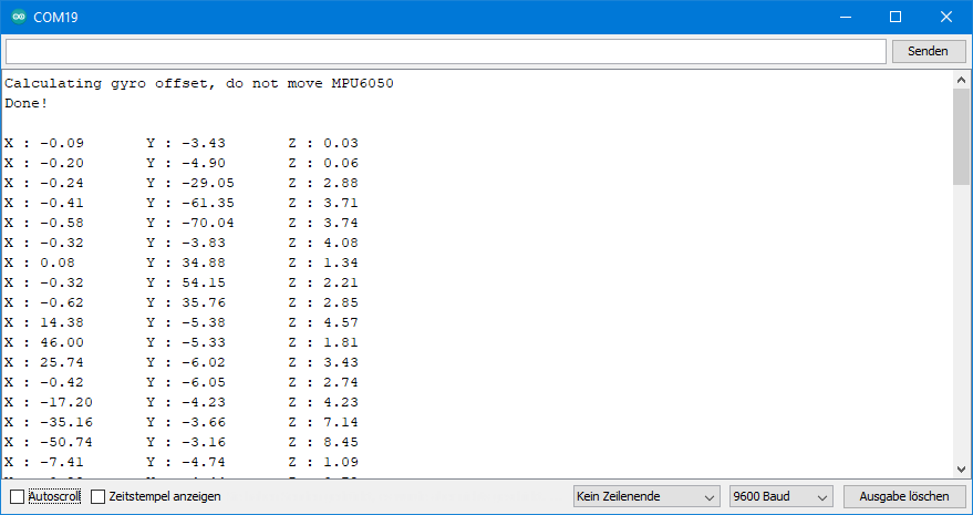
Very interesting is also the library MPU6050_light, which you can find here on GitHub or install via the Arduino IDE. It is kept simple (just “light”, as the name suggests). But it offers the possibility to output tilts, which it calculates from the (earth) acceleration data. A prerequisite for reliable data is that the movements are slow, so that the acceleration due to gravity is the decisive variable. Here is an exemplary output of the sample sketch getAngle.ino. I flipped the xy plane back and forth. This works quite well, but I wouldn’t dispose of my spirit level.
Thank you for sharing your interrupt code, I was able to make my ESP32 WROOM chip wake up from deepsleep and send me a notification. However, I noticed the project was consuming 4mA during deepsleep and I read the MPU6050 might have been the cause. For that reason, I tested the following code, which disables the gyros. However, I did not understand it would “permanently” disable them! I would like to ask your help in finding how to enable them again. Right now, using the MPU6060_Light library, I can only get Acceleration, angle and Temp data, not Gyro. The code that broke my MPU6050: https://github.com/chris-ault/MotionDetector/blob/master/src/main.cpp
Very strange, since all registers should be set to default values, when you disconnect the MPU6050 from power supply, and then re-connect. Also, writeByte( MPU6050_ADDRESS, 0x6C, 7); should not have a permanent effect.
What could happen is the following: you upload the sketch which deactivates the gyroscope. Then you upload another sketch (without re-powering in between) which does not change the register 0x6C. In that case, the gyroscope still won’t work. But latest when you then re-power the MPU6050 it should work. Have you tried to re-power after uploading another sketch?
If it still does not work, you can try to change the sketch that de-activated the gyroscope. Change line 109 from
writeByte( MPU6050_ADDRESS, 0x6C, 7);
to:
writeByte( MPU6050_ADDRESS, 0x6C, 0);
Regards, Wolfgang
I changed the line as you mentioned, turned OFF/ON and your minimum and extended sketches show Gyro data changing again, thank you!
When running the deepsleep-interrupt sketch from Github – by “chris-ault” – I measured a deepsleep current of close to 600uA, as expected. This included removing the LED from the MPU6050 and using an ESP-WROOM-32 bare chip powered by 2xAA batteries. Since my multimeter is very basic, I placed a 0.5 ohm resistor in series with the power supply and measured the voltage across it in the 200mV range (Ohm’s Law did the rest).
I would like to add that your article has a broken hyperlink at “(…) I came across this page(…)”, which should take the reader to: https://www.eluke.nl/2016/08/11/how-to-enable-motion-detection-interrupt-on-mpu6050/
Thank you very much once again and I will be looking forward to your next articles.
Great that it works now! And thanks for informing me about the broken link. I have repaired it now.
Enjoy your projects!
Hi , great document ! I use mpu6050 in my graduatioon design recently . However ,i don’t understand the
principle of this module . Thanks a lot for your article.I want to know more detail about the principle of this module .How it convert the pressure changes to angle changes of three axes . I don’t have a good command of English . it maybe a little difficult for you to understand my message .sorry for that! Waitinng for your answer . Thanks a lot!
Hi, I tried to explain it with the scheme you find at the beginning of the post. The forces change the distance between micro capacitor plates, becaus one is fixed and the other one can move. And the capacity of a capacitor changes with the distance of the plates. And that can be measured. Don’t know how to explain this differently. Some fiurther information is here:
https://en.wikipedia.org/wiki/Microelectromechanical_systems?msclkid=ee064f82cd2311eca4649a36d54483b8
and here:
https://www.althensensors.com/althenpedia/mems-sensors-what-are-they-and-how-do-they-work/
or a little more scientific here:
https://www.tf.uni-kiel.de/matwis/amat/semitech_en/kap_7/backbone/r7_1_3.html
Hope this helps!
Regards, Wolfgang
Thanks a lot ! It’s intereiting .I have a brief understanding about the principle of this module now .It should hava a complex formula between the original data (which can got fro m the modul and change by the subtle change of the frame you mentioned in the begining of this article ) and the angle we finally want .Because i can’t read the data of angle from the modul .
If you know the acceleration values in g then you can calculate the angles of the axes vs the horizontal very easily: angle = arcsin (g-Value). This works well up to ~60°, then it becomes more inprecise. And it only works when the module is not accelerated by anything else than gravity. I have described this here:
https://wolles-elektronikkiste.de/en/mma7361-analog-accelerometer#Anker3
I have set the registers as you mentioned in magic push button but the LED didn’t turn ON.
I just want that LED should turn ON through interrupt whenever i move the MPU6050 sensor.
It works on my side. I think I need some more information, otherwise I can only speculate about the reasons.
Did you use the MPU6050_interrupt.ino sketch as is and have you done the wiring exactly as I have shown in the article? Or have you applied any changes to the sketch or the wiring? If yes, what are the differences? If no, you might want to check if the MPU6050 responds at all – have you tried one of the other sketches? Do they work?
Yes i am using the same sketch MPU6050_interrupt.ino, other sketches are working fine. I tried MPU6050_minimum.ino it is giving the same output as shown.
I am using the below code. I want whenever i move mpu6050. it should turn ON the builtin led of arduino UNO.
#include “Wire.h”
#define MPU6050_ADDR 0x68 // Alternatively set AD0 to HIGH –> Address = 0x69
#define MPU6050_ACCEL_CONFIG 0x1C // Accelerometer Configuration Register
#define MPU6050_PWR_MGT_1 0x6B // Power Management 1 Register
#define MPU6050_INT_PIN_CFG 0x37 // Interrupt Pin / Bypass Enable Configuration Register
#define MPU6050_INT_ENABLE 0x38 // Interrupt Enable Register
#define MPU6050_LATCH_INT_EN 0x05 // Latch Enable Bit for Interrupt
#define MPU6050_ACTL 0x07 // Active-Low Enable Bit
#define MPU6050_WOM_EN 0x06 // Wake on Motion Enable bit
#define MPU6050_WOM_THR 0x1F // Wake on Motion Threshold Register
#define MPU6050_MOT_DUR 0x20 // Motion Detection Duration Register
#define MPU6050_ACCEL_INTEL_CTRL 0x69 // Accelaration Interrupt Control Register
#define MPU6050_SIGNAL_PATH_RESET 0x68 // Signal Path Reset Register
byte interruptPin=2;
byte ledPin=13;
volatile bool accEvent = false;
void setup()
{
Wire.begin();
Serial.begin(9600);
writeRegister(MPU6050_PWR_MGT_1, 0);
setInterrupt(1); // set Wake on Motion Interrupt / Sensitivity; 1(highest sensitivity) – 255
pinMode(ledPin, OUTPUT);
pinMode(interruptPin, INPUT);
attachInterrupt(digitalPinToInterrupt(interruptPin), motion, RISING);
Serial.println(“Setup done”);
}
void loop() {
if(accEvent){
digitalWrite(ledPin, HIGH);
Serial.println(“LED ON”);
delay(1000);
digitalWrite(ledPin, LOW);
Serial.println(“LED OFF”);
delay(1000);
accEvent = false;
attachInterrupt(digitalPinToInterrupt(interruptPin), motion, RISING);
}
}
void setInterrupt(byte threshold){
//writeRegister(MPU6050_SIGNAL_PATH_RESET, 0b00000111); // not(?) needed
// writeRegister(MPU6050_INT_PIN_CFG, 1<<MPU6050_ACTL ); // 1<<MPU6050_LATCH_INT_EN
writeRegister(MPU6050_ACCEL_CONFIG, 0b00000001);
writeRegister(MPU6050_WOM_THR, threshold);
writeRegister(MPU6050_MOT_DUR, 0b00000001); // set duration (LSB = 1 ms)
//writeRegister(MPU6050_ACCEL_INTEL_CTRL, 0x15); // not needed (?)
writeRegister(MPU6050_INT_ENABLE, 1<<MPU6050_WOM_EN);
Serial.println("Registers initialised");
}
void writeRegister(uint16_t reg, byte value){
Wire.beginTransmission(MPU6050_ADDR);
Wire.write(reg);
Wire.write(value);
Wire.endTransmission();
}
void motion(){
accEvent = true;
detachInterrupt(2);
}
Hi Puneet, strange – I tried your sketch on an Arduino UNO and it works fine. Maybe your MPU6050 module is a bit different and you need a pull-down resistor at the INT Pin (10kOhm to GND)? If this doesn’t help it will become a bit diffcult to find the reason for an error which I can’t reproduce.
Hi Wolfgang , I tried with pull down resistor of 10kOhm & 4.7kohm but it’s not working. Can you share your email id so that i can send you the pics of my setup with MPU6050. My email id is iotpuneet@gmail.com
Good idea to continue with e-mail. I have sent a mail. If it is not in your inbox please look in the spam folder.
Hi Wolfgang
I have changed the MPU6050 module and it works fine. Thanks a lot….
Hi Wolfgang
Thank you for sharing your valuable insights into MPU6050.
I have an ESP32 which I currently wake up using the MPU6050_INT pin or by manually pressing an external button to reset.
When the MPU6050 movement is detected the esp sends an email alert.
When the button is pressed the esp will reset.
I want to eliminate the external press button. It is exposed to weather and fails over time. I’d like the MPU6050 to recognised when I tap the unit twice it should reset the ESP32 and when movement occurs it sends an alert email as normal.
I wondered if you know if MPU6050 can generate different Interrupts depending on movement. eg Shake to output constant HIGH or double Tap to output 50uS PULSED HIGH on the MPU6050_INT pin?
The documentation MPU-6000/MPU-6050 Register Map and Descriptions page 26 describes the INT pin configuration. 4.14 Register 55(hex37) – INT Pin / Bypass Enable Configuration INT_PIN_CFG . But it is not clear to me if this function is configurable or how to do it if it is.
My System Description,
In my current ESP32 Schematic the MPU6050_INT outpin to the ESP input pin(32) is held LOW using 4k7.
I set the MPU6050 Reg 0x37 (0x0C) 0b00001100 Interrupt to output HIGH.
“writeByte( MPU6050_ADDRESS, 0x37, 0x0C ); // 0x8C INT pin is active low 0x0C is active high ”
I wake up the ESP32 using input pin 32 wired to MPU6050_INT output pin when movement occurs using the following ESP code
“esp_sleep_enable_ext1_wakeup(BUTTON_PIN_BITMASK,ESP_EXT1_WAKEUP_ANY_HIGH);”
Note. I’m choosing interrupt HIGH rather than LOW as the esp_sleep_enable function does not have an ANY_LOW equivalent.
I’m also using two interrupt pins,
one from the MPU6050 to detect movement,
and one from the external press button to manually rest the ESP32.
This is done by configuring BUTTON_PIN_BITMASK which allows a number of selected esp input pins to activate this ESP wakeup function.
Sorry for such a long description. I would very much appreciate whatever insights you have into the configuration and management of the INT function in MPU6050 so that I can get the MPU6050 to perform two functions (movement detection and ESP Reset) instead of just the current one (movement detection)
Hi, the MPU 6050 can only detect simple movements. There are other modules like the ADXL345 which can detect also single or double taps. The MPU6050 has some undocumented registers but I don’t think there is such function. Maybe you can measure the time between movements. If you shake the MPU6050 you would detect several motion interrupts in short time and that could be the trigger to reset. Would that maybe work for you?
Hi, great documentation!!
I want to use a MPU6050 with a SAMD51 and interruptions to wake up microcontroller on motion.
Is what you describe also useful for Arduino ARM board like SAMD51 or only for AVR? Is there any difference to compile?
Thanks!
Hi,
basically SAMD processors are compatible with the Arduino IDE. Several Arduino boards are based on them. There is a SAMD board package available in the Arduino IDE in the Board manager. You may need additional packages for your specific board. I found a tutorial how to implement a SAMD51 board from Sparkfun:
https://learn.sparkfun.com/tutorials/samd51-thing-plus-hookup-guide/setting-up-the-arduino-ide
So, look if you find something similar for the board you want to use. At least this should show you what is needed to implement a SAMD51 board. If the libraries for the MP6050 are fully compatible with the SAMD51 is something you just need to try or you ask the authors on GitHub directly.
Hope this helps a bit! I would be very interested to hear from you if it worked at the end.
Hello
Good day
Thank you very much for your useful article
I use this sensor to measure the angle of my project. The problem for me is that I can successfully read or write all the sensor registers, but I just always reset the temperature and gyroscope. Unfortunately, all ten modules purchased are the same. I have not had such a problem before.
can you help me?
Thanks a lot
Ghasem Shakourian
Hello Ghasem,
I haven’t heard about such an issue yet. I think I need some more information, before hopefully I can help somehow:
* You say you haven’t had such a problem before. Does this mean the same code works fine with MPU6050 sensors you have purchased before?
* What does reset of temperature and gyroscope mean? Does the module “forget” the parameters like range or filter?
* Do you use a library? Which one?
Best wishes, Wolfgang