
About this post
After introducing the MPU6050 6-axis I2C sensor in the last article, I would like to deal with the simpler MMA7361 3-axis analog acceleration sensor in this post. I will cover the following topics:
- Technical Data / Features
- How to read out the raw data
- g-Value and angle calculation
- Free Fall (0g) Interrupt
- MMA7361 as position sensor (orientation)
Specifications / Properties of the MMA7361

I explained the working principle of accelerometers in my last post.
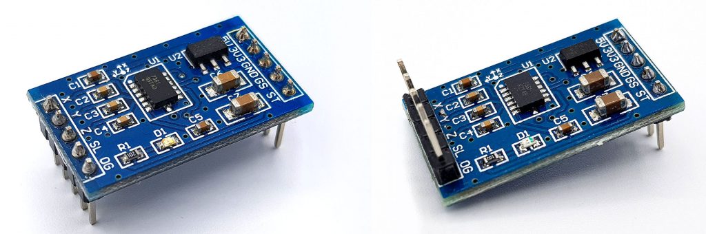
The MMA7361 is a pure accelerometer. The measurement data for acceleration in the x, y and z directions are provided as analog values at the pins X, Y and Z. You will find printed on the module where the x, y and z axes are located.
The MMA7361 module used in this article is operated at 3.3 or 5 volts in contrast to the bare MMA7361 IC. The measuring range can be set to +/-1.5 g (g = gravitational acceleration, not grams!) or +/-6 g. In addition, the MMA7361 has a self-test function and a 0g interrupt (free fall detection). The conversion of the raw data must be done by suitable sketches. For example, a data sheet can be found here.
Here are the most important data at a glance:
- Power supply: 3.3 or 5 V
- Power consumption:
- IC: -0.4 mA (normal operation) / ~3 µA (sleep mode)
- Module: ~1.9 mA – due to the board LED, which you can carefully remove
- 2 Ranges: +/- 1.5 g (GS = LOW) / +/- 6 g (GS = HIGH)
- Sensitivity:
- +/- 1.5 g Range: 800 mV/g
- +/- 6 g Range: 206 mV/g
- 0G detection (active-high)
- Sleep mode (SL = LOW)
- Self test (ST = HIGH): please look at the data sheet
Reading out the raw data of the MMA7361
The raw data can be easily read out via the analog inputs of your Arduino – or whatever microcontroller you use. According to my experience the A/D converter of the Arduino UNO fluctuates strongly with +/- 2 or 3 units. I’ll make up for that in the sketch by averaging 50 values. Alternatively, you might think about using an A/D converter like the ADS1115.
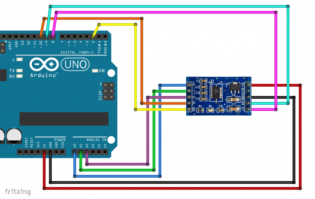
A real nuisance are the dimensions of the module and the fact that the pin headers are already soldered to the module. You can plug the module in a breadboard, but then there is only room for jumper cables on one side. I removed a pinboard and soldered it to the top:
Wiring
The circuit is not a big surprise:
The sketch for reading the raw data
There is not much to say about the sketch either. Except perhaps that I decided to work primarily with integer variables. The fluctuations of the measured values are so high that float values would suggest an accuracy that is simply not given.
int xPin = A0;
int yPin = A1;
int zPin = A2;
int selfTestPin = 8;
int gSelectPin = 9;
int sleepPin = 10;

void setup(){
  Serial.begin(9600);
  pinMode(selfTestPin, OUTPUT);
  pinMode(gSelectPin, OUTPUT);
  pinMode(sleepPin, OUTPUT);
  digitalWrite(sleepPin, HIGH);
  digitalWrite(selfTestPin, LOW);
  digitalWrite(gSelectPin, LOW);
  Serial.println("MMA7361 - Raw Data");
}

void loop(){
  Serial.print("x-Axis: ");
  Serial.print(readMMA7361(xPin));
  Serial.print("     ");
  Serial.print("y-Axis: ");
  Serial.print(readMMA7361(yPin));
  Serial.print("     ");
  Serial.print("z-Axis: ");
  Serial.println(readMMA7361(zPin));
  delay(1000);
}

int readMMA7361(int channel){
  long sum = 0;
  int result = 0;
  for(int i=0; i<50; i++){
    sum += analogRead(channel);
  }
  result = sum / 50;
  return result;
}
The result

For the above values, the MMA7361 was positioned flat on the table, i.e. with its x/y plane. 0 g should act on the x and y axes and 1 g on the z axis. So, one would expect the same readings for x and y. But that is not the case. I tested several modules and the values were usually between 350 and 380 units, i.e. about 1.7 to 1.9 volts. However, the starting value for a given module and a given axis was quite reproducible.
I could confirm the stated sensitivity of 800 mV/g for the range of +/- 1.5g. Converted to “analogRead units” the following applies:
![\[ 5000\; [\text{mV}]\stackrel{\wedge}= 1023 \;\; \rightarrow\;\;800\;[\text{mV}]\stackrel{\wedge}=163.7 \]](https://wolles-elektronikkiste.de/wp-content/ql-cache/quicklatex.com-0995abea5e07874103c64d00806ee7f1_l3.png "Rendered by QuickLaTeX.com")
That means, when I rotated the MMA7361 by 90°, the measured value of the affected axis went up or down by about 163 units. This value is used as aconstant (unitsPerG) in the sketch.
Calculation of acceleration and angle
Zero points of the MMA7361 axes
Before we calculate accelerations and angles, we must first determine the zero points (called “start values” in the further course). In principle, there are two options:
- You determine the maximum and minimum values by slowly rotating and use the mean as the zero point. The zero points are stored as constants.
- You position the MMA7361 flat. The measured values for the x- and y-axis correspond to the zero points. The measured value for the z-axis corresponds to 1 g. This means that the zero point for the z-axis is the measured value minus 800 mV (= 163 units) for the range of +/-1.5 g or measuring value minus 206 mV for +/- 6 g.
I chose method 2. In my sketches, the zero points are recalculated with each reset.
Calculation of acceleration values
Calculating the acceleration a from the zero startVal, the rawVal reading and the slope unitsPerG is simple:
![\[ a = startV\!al+(rawV\!al-startVal)\cdot unitsPerG \]](https://wolles-elektronikkiste.de/wp-content/ql-cache/quicklatex.com-fdc4e1379b66b3e6660cd20cb699f7ba_l3.png "Rendered by QuickLaTeX.com")
Calculation of angles
If the MMA7361 is not moved, a statement about its position in the three-dimensional space can be made by the distribution of the gravitational acceleration on the axes. The following diagram illustrates this with the example of the x-axis:
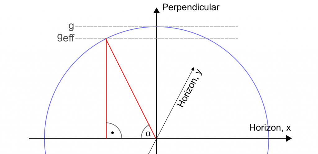
geff is the effective gravitational accelaration force acting on the axis. The following applies to the tilt angle α:
![\[ sin(\alpha)=\frac{g_{ef\!f}}{g} \;\;\;\;\rightarrow\;\;\;\;\alpha=arcsin \left( \frac{g_{ef\!f}}{g}\right) \]](https://wolles-elektronikkiste.de/wp-content/ql-cache/quicklatex.com-fad18927732a3247e2ae9b73ef450855_l3.png "Rendered by QuickLaTeX.com")
However, there are two limitations:
- The angles are not unique. The geff/g value is identical for an angle α and the angle of 180° α.
- The calculation becomes increasingly error-prone the closer you get to 90°.
Regarding the second limitation, here is an example calculation:
![\[ arcsin(0) = 0°\;\;\;\leftrightarrow\;\;\;arcsin(1)=90° \]](https://wolles-elektronikkiste.de/wp-content/ql-cache/quicklatex.com-996ac44355e46ff01b0246c9c725426e_l3.png "Rendered by QuickLaTeX.com")
![\[ arcsin(0.01) = 0.57°\;\;\;\leftrightarrow\;\;\;arcsin(0.99)=81.89° \]](https://wolles-elektronikkiste.de/wp-content/ql-cache/quicklatex.com-0b872822df21afe33dde8c47861da20d_l3.png "Rendered by QuickLaTeX.com")
So, a measurement fluctuation has a rather drastic effect around 90°. However, for tilt angles up to ~60°, the method is quite exact.
Example sketch “All Values”
- The values are stored in an array (x,y,z).
- The asin() function returns the angles in rad. I convert the results to degrees (times 360/2π).
- I tried to format the output nicely with
sprintf. For the g-values (gVal) this became quite complex. I got it, but only with quite a lot of code and then left it out, so that the view of the essentials is preserved. - In some places, I multiply by 1.0. This makes sense to prevent the compiler from providing me with integer values where I want floats.
- To catch errors due to geff/g values greater than 1 (invalid for the asin function), I simply truncate the values when this happens.
const int unitsPerG = 163; // depends on your ADC and the range (1.5g vs 6g)
int axisPin[] = {A0, A1, A2};
int selfTestPin = 8;
int gSelectPin = 9;
int sleepPin = 10;
int startVal[3] = {0};

char result[8]; // for format of the output

void setup(){
  Serial.begin(9600);
  pinMode(selfTestPin, OUTPUT);
  pinMode(gSelectPin, OUTPUT);
  pinMode(sleepPin, OUTPUT);
  digitalWrite(sleepPin, HIGH);
  digitalWrite(selfTestPin, LOW);
  digitalWrite(gSelectPin, LOW);
  getStartVals();
}

void loop(){
  int angles[3] = {0};
  int raw[3] = {0};
  float gVal[3] = {0.0};

  getRawVals(raw);
  getAngles(angles,raw);
  getGValues(gVal, raw);
  Serial.print("x-Raw:  "); sprintf(result,"%6d", raw[0]); // sprintf for format
  Serial.print(result);
  Serial.print("     ");
  Serial.print("y-Raw:  "); sprintf(result,"%6d", raw[1]);
  Serial.print(result);
  Serial.print("     ");
  Serial.print("z-Raw:  "); sprintf(result,"%6d", raw[2]);
  Serial.println(result);

  Serial.print("x-Angle:  "); sprintf(result,"%4d", angles[0]);
  Serial.print(result);
  Serial.print("     ");
  Serial.print("y-Angle:  "); sprintf(result,"%4d", angles[1]);
  Serial.print(result);
  Serial.print("     ");
  Serial.print("z-Angle:  "); sprintf(result,"%4d", angles[2]);
  Serial.println(result);

  Serial.print("x-g:      ");
  Serial.print(gVal[0]);
  Serial.print("     ");
  Serial.print("y-g:      ");
  Serial.print(gVal[1]);
  Serial.print("     ");
  Serial.print("z-g:      ");
  Serial.println(gVal[2]);
  Serial.println();

  delay(1000);
}

void getGValues(float gValueArray[], int rawArray[]){
  for(int i=0; i<3; i++){
    int diff = rawArray[i] - startVal[i];
    gValueArray[i] = diff*1.0/unitsPerG;
  }
}

void getRawVals(int rawVals[]){
  for(int i=0; i<3; i++){
    rawVals[i] = readMMA7361(axisPin[i]);
  }
}

void getAngles(int angleArray[], int rawArray[]){
  bool positive = true;
  for(int i=0; i<3; i++){
    int diff = rawArray[i] - startVal[i];
    positive = (diff>=0);
    diff = abs(diff);
    if(diff > unitsPerG){
      diff = unitsPerG;
    }
    angleArray[i] = int((asin(diff*1.0/unitsPerG))*57.296);
    if(positive==false){
      angleArray[i] = -angleArray[i];
    }
  }
}

int readMMA7361(int pin){
  long sum = 0;
  int result = 0;
  for(int i=0; i<50; i++){  // mean value of 50 measurements
    sum += analogRead(pin);
  }
  result = sum / 50;
  return result;
}

void getStartVals(){
  Serial.println("Your MMA71361 should now be placed flat on the ground, i.e.:");
  Serial.println("x/y-axis = 0 degrees, z-axis = 90 degrees ");
  Serial.print("Wait....");
  delay(2000); // to have enough time to position the MMA7361
  for(int i=0; i<3; i++){
    startVal[i] = readMMA7361(axisPin[i]);
  }
  startVal[2] -= unitsPerG; // Z-axis is at 90° in start position!
  Serial.println("ready!");
}
The result
Here’s what a result might look like:
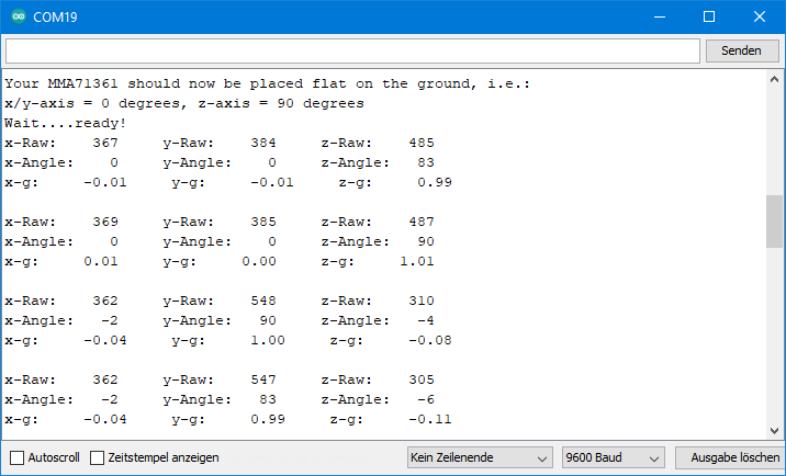
You can see how I turned the MMA7361 by 90° between the second and third measuring blocks.
Free Fall (0 g) Interrupt
The pin 0G is low in normal condition. If “0 g” is measured simultaneously on all axes (according to the data sheet -0.4 g to + 0.4 g), the pin 0G goes to HIGH. The 0 g state occurs in free fall, but possibly also in vibration.
Here’s how you could use the signal:
int selfTestPin = 8;
int gSelectPin = 9;
int sleepPin = 10;
int zeroGPin = 2;

volatile bool fall = false;

void setup(){
  Serial.begin(9600);
  pinMode(selfTestPin, OUTPUT);
  pinMode(gSelectPin, OUTPUT);
  pinMode(sleepPin, OUTPUT);
  pinMode(zeroGPin, INPUT);
  attachInterrupt(digitalPinToInterrupt(zeroGPin), zeroG, RISING);
  digitalWrite(sleepPin, HIGH);
  digitalWrite(selfTestPin, LOW);
  digitalWrite(gSelectPin, LOW);
  Serial.println("Free Fall Interrupt for MMA7261 active...");
  delay(100);
  fall = false;
}

void loop(){
  if(fall==true){
    Serial.println("Aaaaaaaaah!!!!! - I'm faaaaallllling!");
    delay(1000);
  }
  fall = false;
}

void zeroG(){
  fall = true;
}
The free fall interrupt is relatively sensitive. It can already be triggered when you tap on the table on which the MMA7361 is placed. To prevent it from triggering even with a short vibration, you can use a small trick.
First, you change the interrupt condition from RISING to HIGH. If an interrupt is triggered, then after a short time (I have chosen 100 ms in the example sketch) it is checked for another short time (e.g. 50 ms) whether the 0G pin is still active.
int selfTestPin = 8;
int gSelectPin = 9;
int sleepPin = 10;
int zeroGPin = 2;

volatile bool fall = false;

void setup(){
  Serial.begin(9600);
  pinMode(selfTestPin, OUTPUT);
  pinMode(gSelectPin, OUTPUT);
  pinMode(sleepPin, OUTPUT);
  pinMode(zeroGPin, INPUT);
  attachInterrupt(digitalPinToInterrupt(zeroGPin), zeroG, HIGH);
  digitalWrite(sleepPin, HIGH);
  digitalWrite(selfTestPin, LOW);
  digitalWrite(gSelectPin, LOW);
  Serial.println("Free Fall Interrupt for MMA7261 active...");
  delay(100);
  fall = false;
}

void loop(){
  if(fall==true){
    delay(100);
    fall = false;
    delay(50);
      if(fall==true){
        Serial.println("Aaaaaaaaah!!!!! - I'm faaaaallllling!");
        delay(1000);
      }
    fall = false;
  }
}

void zeroG(){
  fall = true;
}
Just play around with the delay times to customize the interrupt function to your needs.
The MMA7361 as orientation sensor
In the last section, I want to show you how to use the MMA7361 as an orientation sensor. By this I mean the determination of the 6 main directions in three-dimensional space, which I refer to as follows (view from the side):
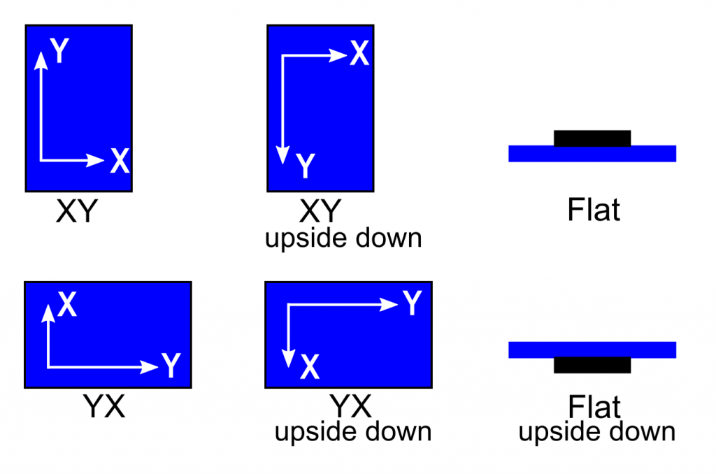
In principle, it is simple. First, the angles are determined. The axes with an angle (absolute value) less than 45° are considered to be horizontal, the axis with an angle (absolute value) greater than or equal to 45° as vertical. Depending on whether the vertical axis has a positive or negative angle, it points up or down. And the following sketch simply checks this systematically. I did not consider the special case that two axes have exactly 45°.
const int unitsPerG = 163;
int axisPin[] = {A0, A1, A2};
int selfTestPin = 8;
int gSelectPin = 9;
int sleepPin = 10;
int startVal[3] = {0};

enum MMA7361_ORIENTATION{
  FLAT, FLAT_1, XY, XY_1, YX, YX_1
} orientation;

void setup(){
  Serial.begin(9600);
  pinMode(selfTestPin, OUTPUT);
  pinMode(gSelectPin, OUTPUT);
  pinMode(sleepPin, OUTPUT);
  digitalWrite(sleepPin, HIGH);
  digitalWrite(selfTestPin, LOW);
  digitalWrite(gSelectPin, LOW);
  getStartVals();
}

void loop(){
  int angles[3] = {0};
  int raw[3] = {0};

  getRawVals(raw);
  getAngles(angles,raw);
  getOrientation(angles);
  printOrientation();

  delay(1000);
}

void getRawVals(int rawVals[]){
  for(int i=0; i<3; i++){
    rawVals[i] = readMMA7361(axisPin[i]);
  }
}

void getAngles(int angleArray[], int rawArray[]){
  bool positive = true;
  for(int i=0; i<3; i++){
    int diff = rawArray[i] - startVal[i];
    positive = (diff>=0);
    diff = abs(diff);
    if(diff > unitsPerG){
      diff = unitsPerG;
    }
    angleArray[i] = int((asin(diff*1.0/unitsPerG))*57.296);
    if(positive==false){
      angleArray[i] = -angleArray[i];
    }
  }
}

int readMMA7361(int pin){
  long sum = 0;
  int result = 0;
  for(int i=0; i<50; i++){
    sum += analogRead(pin);
  }
  result = sum / 50;
  return result;
}

void getStartVals(){
  Serial.println("Your MMA71361 should now be placed flat on the ground, i.e.:");
  Serial.println("x/y-axis = 0 degrees, z-axis = 90 degrees ");
  Serial.print("Wait....");
  delay(2000);
  for(int i=0; i<3; i++){
    startVal[i] = readMMA7361(axisPin[i]);
  }
  startVal[2] -= unitsPerG; // Z-axis is at 90° start position!
  Serial.println("ready!");
}

void getOrientation(int angleArray[]){
  if(abs(angleArray[0])<45){      // |x| < 45
    if(abs(angleArray[1])<45){    // |y| < 45
      if(angleArray[2]>0){        //  z  > 0
        orientation = FLAT;
      }
      else{                       //  z  < 0
        orientation = FLAT_1;
      }
    }
    else{                         // |y| > 45
      if(angleArray[1]>0){        //  y  > 0
        orientation = XY;
      }
      else{                       //  y  < 0
        orientation = XY_1;
      }
    }
  }
  else{                           // |x| >= 45
    if(angleArray[0]>0){          //  x  >  0
      orientation = YX;
      }
      else{                       //  x  <  0
        orientation = YX_1;
      }
  }
}

void printOrientation(){
  Serial.print("Orientierung: ");

  switch(orientation){
    case FLAT:
      Serial.println("Flat");
      break;
    case FLAT_1:
      Serial.println("Flat - upside down");
      break;
    case XY:
      Serial.println("XY");
      break;
    case XY_1:
      Serial.println("XY - upside down");
      break;
    case YX:
      Serial.println("YX");
      break;
    case YX_1:
      Serial.println("YX - upside down");
      break;
  }
}
Acknowledgement
The rocket in the post image I owe Satheesh Sankaran on Pixabay.
Hello….why need multiplied with 57.296, what variable or constanta ? (i found in this code):
” angleArray[i] = int((asin(diff*1.0/unitsPerG))*57.296);
Hi, the asin function returns the angle in rad. I think most people prefer angles in degree.
1 rad = 180°/Pi
==> 1 rad≈57,2957795°