About this Post
In my last two posts I had reported on the 6-axis sensor MPU6050 and the rather simple accelerometer MMA7361 with analog output. In this article, I will now focus on the ADXL345 3-axis acceleration sensor (which includes the ADXL343). With its many features, it is for me the Swiss army knife among the accelerometers.
I found a lot of libraries for the ADXL345. But I felt they were all either not complete or written in such a way that you still have to go deep into the data sheet to use them. This motivated me to write a library myself, which – at least from my point of view – is convenient to use. To make it easy to use more complex functions such as FIFO, I have added 15 example sketches to the library. Due to this large scope, I had to split the article into two parts (click here for part 2).
Update 04/16/2025: I have added a separate class for the ADXL343 to the library. The same applies to the “defines” such as ADXL343_RANGE_8G. Since the ADXL343 and ADXL345 have identical registers, the ADXL345 sketches also work unchanged on the ADXL343.
Features / Technical specifications of the ADXL345 (and ADXL343)
I had already described the operating principle of accelerometers in detail in my post about the MPU6050.
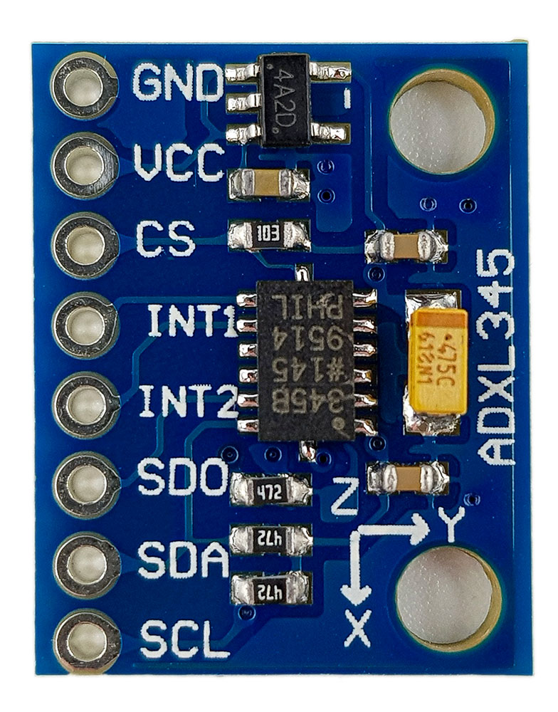
As with other sensors, I did not use the bare ADXL345 IC for simplicity, but rather a module. These usually have:
- Pull-up resistors for the I2C lines.
- A capacitor for voltage stabilization.
- A voltage converter so that you can operate the module with 3-5 volts.
The disadvantage of the module compared to the IC is that the power consumption is slightly higher. In the normal operating mode at measuring frequencies below 10 Hz, the consumption of the actual IC should be at 30 µA. I measured 100 µA at 5 V supply voltage, and at 3.3 V it was 50 µA.
The most important data at a glance
- Measuring ranges: +/-2, +/-4, +/-8, +/-16 g.
- Resolution: 13 bits in the maximum measuring range (typically 4 mg / LSB)
- Adjustable to 10 bits for all measuring ranges.
- Communication via I2C or SPI (both implemented).
- Single and double tap detection, i.e. detection of short accelerations, e.g. due to vibrations.
- FIFO (first in, first out) buffer memory for 32 readings.
- 8 interrupts, including free fall, single and double tap, activity and inactivity, FIFO overflow.
- Interrupts can be assigned to two output pins.
- Power supply: 3 – 5 volts (for the module).
- Power consumption (according to my measurements):
- from 23 µA (stand-by mode, 3.3 volts operating voltage)
- up to 220 µA (normal mode, 3200 Hz measuring frequency, 5 volts operating voltage).
- Various energy-saving modes.
The best way to explain the features of the ADXL345 is to go through the example sketches.
Wiring the ADXL345 to the Arduino (I2C)
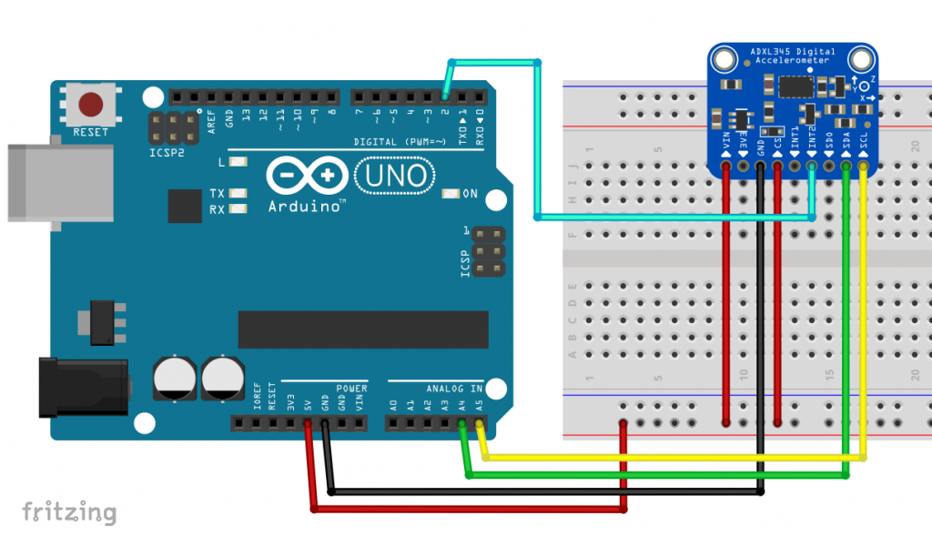
The wiring shown above was used for all example sketches.
- VCC/GND: 3 – 5 volts.
- 3V3 is a special feature of the Adafruit module: 3.3 volts are provided there.
- CS (Chip Select): when connected to GND, the module is no longer accessible via I2C; so connect it to VCC. Or to an I/O pin, then you can operate more than two ADXL345.
- SDA/SCL: I2C pins; pull-ups should be present on the module.
- SDO: Choice of I2C address. For 0x53 leave the pin unconnected or attach it to GND, for 0x1D you connect it to VCC.
- INT1/INT2: Interrupt Pins; you can assign the interrupts to these pins. In addition, the interrupts can be set active-high or active-low.
The underlying ADXL345 IC can only handle 2.0 – 3.6 volts. This applies to both the power supply and the data pins. Many modules only regulate the supply voltage down, but do not take care of the data pins. The Adafruit modules are one of the laudable exceptions (see here). If necessary, add a level shifter. Normally, 3.3 volt components do not break so quickly even at 5 volts on the data lines, but it can affect the service life.
Using SPI
And this is what the connection via SPI looks like (here with an Arduino Nano):
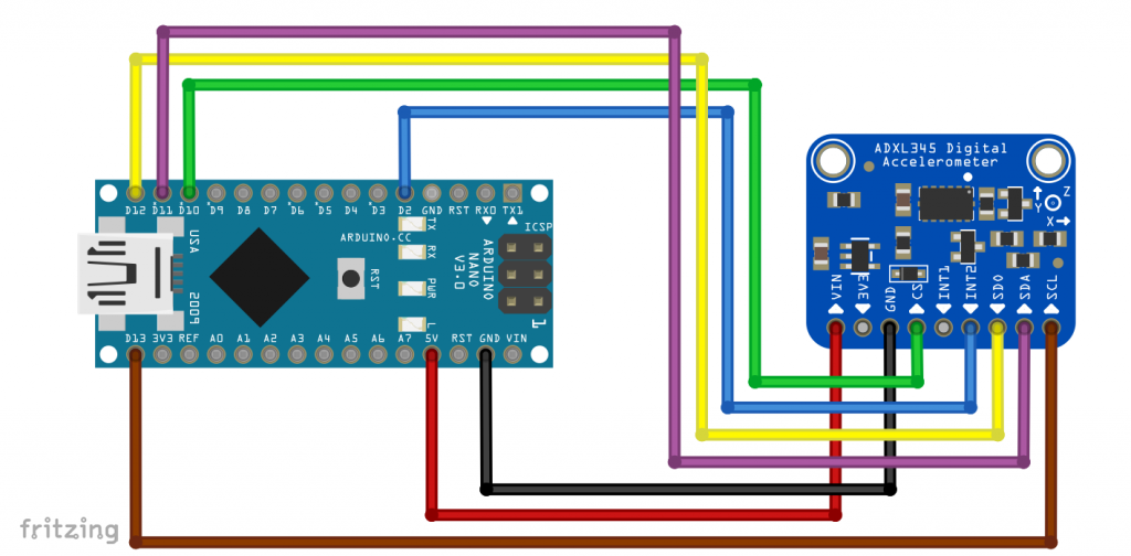
Here too, you may need to place a level shifter between the microcontroller and the ADXL345.
SPI (4-wire) does not work out of the box with this module:

The problem is that SDO is pulled to GND via the 0 Ω resistor R4. SPI 3-Wire would work, but I have not implemented it. Simple remedy: Remove the resistor (desolder or use “careful force”).
Operation with the library ADXL345_WE
You can download the library ADXL345_WE here from Github. For installation, unzip the ZIP file in the Arduino Library folder. Alternatively, you can install it via the Arduino IDE Library Manager.
As mentioned at the beginning, I tried to make the library user-friendly. Nevertheless, it has become very extensive. This is simply due to the many features of the ADXL345.
I will now guide you through the library using the example sketches. The sketches can be grouped according to the following themes:
- Basics functions
- interrupts
- Activity, inactivity features
- Single and double tap detection
- FIFO Functions
I have added lots of comments in all sketches and inserted parameter lists for the functions. But since this can also distract from the essentials, I only print the first sketch completely here. For the others, I take out many comments. If you want to try out the sketches or build on them, take the detailed versions you download with the library.
The post is quite long. Impatient people can also simply try the sample sketches and return here if something should be unclear.
Basic functions of the ADXL345
The ADXL345 stores the determined acceleration values as raw data, which are provided in the data registers for the x, y and z axes. You get the latest values there. The maximum “age” of these depends on the measurement frequency (data rate). A high frequency leads to increased noise and power consumption. So don’t overdo it unnecessarily.
The raw values are converted into acceleration values in g by the library. As a first approximation, the conversion factor in full resolution is 3.9 mg (= milli-g, not milligrams!) per LSB (= Least Significant Bit). In other words:
![\[ \text{accelerationValue in mg} = \text{rawValue}\cdot3.9 \]](https://wolles-elektronikkiste.de/wp-content/ql-cache/quicklatex.com-f3b412a4ed23e8f9561a8db7328a7348_l3.png "Rendered by QuickLaTeX.com")
For result data, such as raw data, g-values or angles, I have defined the structure (struct) xyzFloat. An xyzFloat consists of three float variables. The raw data “raw” includes, for example, the axis values raw.x, raw.y and raw.z.
Example sketch 1: ADXL345_basic_data.ino
Let’s get started. In the first example sketch, you will learn about the following features:
ADXL345_WE myAcc = ADXL345_WE( )creates the object myAcc (stands for “my Accelerometer”). You can pass the I2C address and / or a TwoWire object. The latter option allows you to use both I2C buses on one ESP32.init()initializes the ADXL345 with some default values. The function returns true if the ADXL345 responds as expected.setDataRate(range)sets the measuring frequency. Select from the parameter list.setRange(range)sets the g-range. Select from the parameter list.setFullRange(true/false)sets the full resolution (10-13 bits) or the reduced resolution (10 bits). The full resolution is preset. I see no reason to change that.getDataRateAsString()returns the set measuring frequency as a string.getRangeAsString()returns the g-range as a string.setLowPower(true/false)sets the Low Power Mode. It provides power savings for certain data rates at the price of slightly higher noise.
As an alternative to the “get as string” functions, you can also use the following functions:
getRange()/getDataRate()
But then you will only get numerical values returned, which you have to “translate”. Look at the library file ADXL345_WE.h for the details of the corresponding enum definitions.
#include<Wire.h>
#include<ADXL345_WE.h>
#define ADXL345_I2CADDR 0x53 // 0x1D if SDO = HIGH

/* There are several ways to create your ADXL345 object:
 * ADXL345_WE myAcc = ADXL345_WE()                -> uses Wire / I2C Address = 0x53
 * ADXL345_WE myAcc = ADXL345_WE(ADXL345_I2CADDR) -> uses Wire / ADXL345_I2CADDR
 * ADXL345_WE myAcc = ADXL345_WE(&wire2)          -> uses the TwoWire object wire2 / ADXL345_I2CADDR
 * ADXL345_WE myAcc = ADXL345_WE(&wire2, ADXL345_I2CADDR) -> all together
 */
ADXL345_WE myAcc = ADXL345_WE(ADXL345_I2CADDR);

void setup(){
  Wire.begin();
  Serial.begin(115200);
  Serial.println("ADXL345_Sketch - Basic Data");
  Serial.println();
  if(!myAcc.init()){
    Serial.println("ADXL345 not connected!");
  }

/* Choose the data rate         Hz
    ADXL345_DATA_RATE_3200    3200
    ADXL345_DATA_RATE_1600    1600
    ADXL345_DATA_RATE_800      800
    ADXL345_DATA_RATE_400      400
    ADXL345_DATA_RATE_200      200
    ADXL345_DATA_RATE_100      100
    ADXL345_DATA_RATE_50        50
    ADXL345_DATA_RATE_25        25
    ADXL345_DATA_RATE_12_5      12.5
    ADXL345_DATA_RATE_6_25       6.25
    ADXL345_DATA_RATE_3_13       3.13
    ADXL345_DATA_RATE_1_56       1.56
    ADXL345_DATA_RATE_0_78       0.78
    ADXL345_DATA_RATE_0_39       0.39
    ADXL345_DATA_RATE_0_20       0.20
    ADXL345_DATA_RATE_0_10       0.10
*/
  myAcc.setDataRate(ADXL345_DATA_RATE_50);
  delay(100);
  Serial.print("Data rate: ");
  Serial.print(myAcc.getDataRateAsString());

/* In full resolution the size of the raw values depend on the range:
    2g = 10 bit; 4g = 11 bit; 8g = 12 bit; 16g =13 bit;
    uncomment to change to 10 bit for all ranges.
 */
  // myAcc.setFullRes(false);

/* Choose the measurement range
    ADXL345_RANGE_16G    16g
    ADXL345_RANGE_8G      8g
    ADXL345_RANGE_4G      4g
    ADXL345_RANGE_2G      2g
*/
  myAcc.setRange(ADXL345_RANGE_4G);
  Serial.print("  /  g-Range: ");
  Serial.println(myAcc.getRangeAsString());
  Serial.println();

/* Uncomment to enable Low Power Mode. It saves power but slightly
    increases noise. LowPower only affetcs Data Rates 12.5 Hz to 400 Hz.
*/
  // myAcc.setLowPower(true);
}

/* The LSB of the Data registers is 3.9 mg (milli-g, not milligramm).
    This value is used calculating g from raw. However, this is an ideal
    value which you might want to calibrate.
*/

void loop() {
  xyzFloat raw;
  xyzFloat g;
  myAcc.getRawValues(&raw);
  myAcc.getGValues(&g);

  Serial.print("Raw-x = ");
  Serial.print(raw.x);
  Serial.print("  |  Raw-y = ");
  Serial.print(raw.y);
  Serial.print("  |  Raw-z = ");
  Serial.println(raw.z);

  Serial.print("g-x   = ");
  Serial.print(g.x);
  Serial.print("  |  g-y   = ");
  Serial.print(g.y);
  Serial.print("  |  g-z   = ");
  Serial.println(g.z);

  Serial.println();

  delay(1000);
}
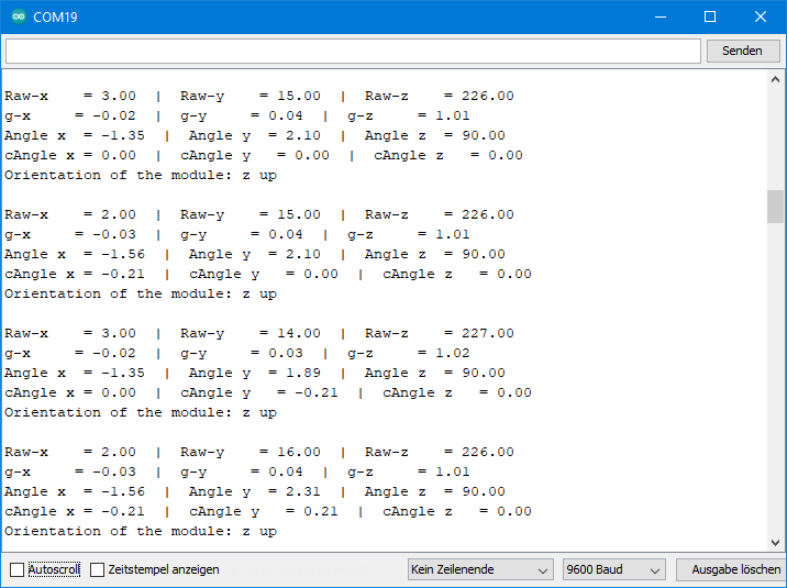
Output of ADXL345_basic_data.ino
For the following output, I tried to position the ADXL345 flat. The raw- and g-values for the x- and y-axes should therefore be zero. The g-value of the z-axis should be 1.

You can see small deviations for the x- and y-values and a not insignificant deviation for the z-value. The deviations vary from module to module. The accelerometer is a micromechanical component with certain tolerances.
You may have noticed that the first set of values differs more. It is advisable to discard these first values at program startup, when returning from stand-by mode and some other states. In this specific case, you could simply insert a small delay at the end of the setup.
Example sketch 2: ADXL345_calibration.ino
This sketch is a guide to calibrating the ADXL345. Start the sketch and do not change the resolution. Rotat the ADXL345 slowly and try to find the maximum and minimum raw values for the axes. Support your arms because trembling distorts the values. It does not matter one or two units. Write down the values and then use them in the further sketches. How you do this, you will learn see in the example sketch 3.
The maximum and minimum values are +1 g and -1 g respectively (if you perform calibration on our home planet!). For the zero points, according to this method, the following applies:
![\[ \text{rawValue}_0 = \frac{\text{rawValue}_{\text{min}}+\text{rawValue}_{\text{max}}}{2} \]](https://wolles-elektronikkiste.de/wp-content/ql-cache/quicklatex.com-8cfc65b6504ae96254ab3dde31a110bb_l3.png "Rendered by QuickLaTeX.com")
Accordingly, an offset is calculated from it. The following applies to the slope:
![\[ \text{slope}\;[\text{gValue/rawValue}] = \frac{|\text{rawValue}_{\text{min}}|+\text{rawValue}_{\text{max}}}{2} \]](https://wolles-elektronikkiste.de/wp-content/ql-cache/quicklatex.com-506069c96f4541c0178587f1b110ce4c_l3.png "Rendered by QuickLaTeX.com")
#include<Wire.h>
#include<ADXL345_WE.h>
#define ADXL345_I2CADDR 0x53  // 0x1D if SDO = HIGH

/* There are several ways to create your ADXL345 object:
 * ADXL345_WE myAcc = ADXL345_WE()                -> uses Wire / I2C Address = 0x53
 * ADXL345_WE myAcc = ADXL345_WE(ADXL345_I2CADDR) -> uses Wire / ADXL345_I2CADDR
 * ADXL345_WE myAcc = ADXL345_WE(&wire2)          -> uses the TwoWire object wire2 / ADXL345_I2CADDR
 * ADXL345_WE myAcc = ADXL345_WE(&wire2, ADXL345_I2CADDR) -> all together
 */
ADXL345_WE myAcc = ADXL345_WE(ADXL345_I2CADDR);

void setup(){
  Wire.begin();
  Serial.begin(115200);
  Serial.println(F("ADXL345_Sketch - Calibration"));
  Serial.println();
  if(!myAcc.init()){
    Serial.println(F("ADXL345 not connected!"));
  }
  Serial.println(F("Calibration procedure:"));
  Serial.println(F(" - stay in full resolution"));
  Serial.println(F(" - supply voltage has influence (at least for the modules)"));
  Serial.println(F("        -> choose the same voltage you will use in your project!"));
  Serial.println(F(" - turn your ADXL slowly (!) to find the min and max raw x,y and z values"));
  Serial.println(F(" - deviations of one or two units don't matter much"));
  Serial.println(F(" - the calibration changes the slope of g vs raw and assumes zero is (min+max)/2 "));
  Serial.println(F(" - write down the six values "));
  Serial.println(F(" - you can try the calibration values in ADXL345_angles_tilt_orientation.ino example sketch"));
  Serial.println(F(" - ready to go? Then type in any key and send. "));
  while(!Serial.available());
  Serial.read();
  Serial.println(); Serial.println(); Serial.println();
}

void loop() {
  xyzFloat raw;
  myAcc.getRawValues(&raw);
  Serial.print(F("Raw-x = "));
  Serial.print(raw.x);
  Serial.print(F("  |  Raw-y = "));
  Serial.print(raw.y);
  Serial.print(F("  |  Raw-z = "));
  Serial.println(raw.z);

  delay(1000);
}
The values I determined were: xmin = -266.0, xmax = 285.0, ymin = -268.0, ymax = 278.0, zmin = -291.0, zmax = 214.0.
Despite the calibration, you will see some deviations because the zero point is not necessarily really in the middle between the min and max values.
Others suggest attaching the ADXL345 to a cube- or square-shaped body to better align it for calibration. However, this assumes that the ADXL345 has been soldered truly flat to the module and that the module is mounted equally flat to the auxiliary body.
Sample sketch 3: ADXL345_angles_orientation.ino
Here you can now apply the calibration by entering the values just obtained in the following function:
setCorrFactors(xmin, xmax, ymin, ymax, zmin, zmax)
The function getRawValues() still provides the uncorrected raw data. getGValues(), on the other hand, uses the corrected values. This also applies to all other sketches.
The sketch also calculates the angles of the axes to the horizontal from the g values. Up to angles of 60° this works well for x and y. In the next section, you’ll learn about another function that covers higher angles. Here, however, the following simple function is used:
![\[ angle = \arcsin(\text{gValue}) \]](https://wolles-elektronikkiste.de/wp-content/ql-cache/quicklatex.com-a76b62d93d8b9efaa5aeaa0f0346d9c0_l3.png "Rendered by QuickLaTeX.com")
I explained why this is so and why values close to 90° are particularly erroneous in my last post. You get the angles via the function getAngles(). Since the arcsin function is not defined for values greater than 1, I simply cut g-values greater than 1.
If you want to measure angles up to 60° quite accurately and want to start at 0°, you can eliminate the offset that still exists despite calibration. For this purpose, you position the ADXL345 as flat and steady as possible and execute the function measureAngleOffsets(). After that, you will receive the additionally corrected values via getCorrAngles().
The last function I want to introduce for this sketch is getOrientationAsString(). This determines which axis is most upwards. Depending on the orientation, it returns: x up, x down, y up, y down, z up or z down as a string.
#include<Wire.h>
#include<ADXL345_WE.h>
#define ADXL345_I2CADDR 0x53 // 0x1D if SDO = HIGH

/* There are several ways to create your ADXL345 object:
 * ADXL345_WE myAcc = ADXL345_WE()                -> uses Wire / I2C Address = 0x53
 * ADXL345_WE myAcc = ADXL345_WE(ADXL345_I2CADDR) -> uses Wire / ADXL345_I2CADDR
 * ADXL345_WE myAcc = ADXL345_WE(&wire2)          -> uses the TwoWire object wire2 / ADXL345_I2CADDR
 * ADXL345_WE myAcc = ADXL345_WE(&wire2, ADXL345_I2CADDR) -> all together
 */
ADXL345_WE myAcc = ADXL345_WE(ADXL345_I2CADDR);

void setup(){
  Wire.begin();
  Serial.begin(115200);
  Serial.println("ADXL345_Sketch");
  Serial.println();
  if(!myAcc.init()){
    Serial.println("ADXL345 not connected!");
  }

/* Add your min and max raw values you found with ADXL345_calibration.ino.
 *  The order is: setCorrFactors(min x, max x, min y, max y, min z, max z).
 *  setCorrFactors calibrates the slope and assumes the zero point
 *  is (min+max)/2. You have to add the setCorrFactors function to all sketches
 *  in which you want to use it.
*/
//  myAcc.setCorrFactors(-266.0, 285.0, -268.0, 278.0, -291.0, 214.0);

/* In this next step the offset for angles is corrected to get quite precise corrected
 *  angles for x and y up to ~60°. The additional offsetCorrection is only used for
 *  corrected angles measurements. The procedure just ensures to start at 0°.
*/
  Serial.println("Position your ADXL345 flat and don't move it");
  delay(2000);
  myAcc.measureAngleOffsets();
  Serial.println("....done");

/* Choose the data rate         Hz
    ADXL345_DATA_RATE_3200    3200
    ADXL345_DATA_RATE_1600    1600
    ADXL345_DATA_RATE_800      800
    ADXL345_DATA_RATE_400      400
    ADXL345_DATA_RATE_200      200
    ADXL345_DATA_RATE_100      100
    ADXL345_DATA_RATE_50        50
    ADXL345_DATA_RATE_25        25
    ADXL345_DATA_RATE_12_5      12.5
    ADXL345_DATA_RATE_6_25       6.25
    ADXL345_DATA_RATE_3_13       3.13
    ADXL345_DATA_RATE_1_56       1.56
    ADXL345_DATA_RATE_0_78       0.78
    ADXL345_DATA_RATE_0_39       0.39
    ADXL345_DATA_RATE_0_20       0.20
    ADXL345_DATA_RATE_0_10       0.10
*/
  myAcc.setDataRate(ADXL345_DATA_RATE_50);
  Serial.print("Data rate: ");
  Serial.print(myAcc.getDataRateAsString());

/* Choose the measurement range
    ADXL345_RANGE_16G    16g
    ADXL345_RANGE_8G      8g
    ADXL345_RANGE_4G      4g
    ADXL345_RANGE_2G      2g
*/
  myAcc.setRange(ADXL345_RANGE_2G);
  Serial.print("  /  g-Range: ");
  Serial.println(myAcc.getRangeAsString());
  Serial.println();
}

void loop() {
  xyzFloat raw, g, angle, corrAngle;
  myAcc.getRawValues(&raw);
  myAcc.getGValues(&g);
  myAcc.getAngles(&angle);
  myAcc.getCorrAngles(&corrAngle);

/* Still the uncorrected raw values!! */
  Serial.print("Raw-x    = ");
  Serial.print(raw.x);
  Serial.print("  |  Raw-y    = ");
  Serial.print(raw.y);
  Serial.print("  |  Raw-z    = ");
  Serial.println(raw.z);

/* g values use the corrected raws */
  Serial.print("g-x     = ");
  Serial.print(g.x);
  Serial.print("  |  g-y     = ");
  Serial.print(g.y);
  Serial.print("  |  g-z     = ");
  Serial.println(g.z);

/* Angles use the corrected raws. Angles are simply calculated by
    angle = arcsin(g Value) */
  Serial.print("Angle x  = ");
  Serial.print(angle.x);
  Serial.print("  |  Angle y  = ");
  Serial.print(angle.y);
  Serial.print("  |  Angle z  = ");
  Serial.println(angle.z);

/* Corrected angles use corrected raws and an extra angle
    offsets to ensure they start at 0°
*/
  Serial.print("cAngle x = ");
  Serial.print(corrAngle.x);
  Serial.print("  |  cAngle y   = ");
  Serial.print(corrAngle.y);
  Serial.print("  |  cAngle z   = ");
  Serial.println(corrAngle.z);

  Serial.print("Orientation of the module: ");
  Serial.println(myAcc.getOrientationAsString());

  Serial.println();

  delay(1000);
}
Output of ADXL_angles_orientation
You can see that the corrected g-values for the z-axis now look much better. The angles have a certain deviation due to the remaining offset. The corrected angles, on the other hand, fluctuate close to zero.
Example sketch 4: ADXL345_pitch_roll_corrected_angles.ino
I have taken the method of angular calculation described here from other libraries, such as MPU6050 light or Arduino-ADXL345. The advantage of this method is that it includes several axes and thus compensates for errors. To delineate the method, I have adopted the nomenclature of others and referred to the tilt angle of the x-axis as “pitch” and that of the y-axis as “roll”. You can find a definition for the “pitch” and “roll” angles here, for example.
![\[ pitch\; angle= \arctan \left(\frac{-g_x}{\sqrt{g_y^2 +g_z^2}}\right) \]](https://wolles-elektronikkiste.de/wp-content/ql-cache/quicklatex.com-be8f8dd16b2c7d25cdc636ad3bc340ed_l3.png "Rendered by QuickLaTeX.com")
![\[ roll\;angle = \arctan\left( \frac{g_y}{g_z} \right) \]](https://wolles-elektronikkiste.de/wp-content/ql-cache/quicklatex.com-985ee479406f587fe4196dc2994b0edc_l3.png "Rendered by QuickLaTeX.com")
Again, of course, the angle determination is only valid in the static state. Additional accelerations distort the result.
Here is the example sketch, or more precisely its main components. As a reminder: the original sample sketches are provided with many more comments.
For comparison, the method from the previous sketch is also used.
#include<Wire.h>
#include<ADXL345_WE.h>
#define ADXL345_I2CADDR 0x53 // 0x1D if SDO = HIGH

/* There are several ways to create your ADXL345 object:
 * ADXL345_WE myAcc = ADXL345_WE()                -> uses Wire / I2C Address = 0x53
 * ADXL345_WE myAcc = ADXL345_WE(ADXL345_I2CADDR) -> uses Wire / ADXL345_I2CADDR
 * ADXL345_WE myAcc = ADXL345_WE(&wire2)          -> uses the TwoWire object wire2 / ADXL345_I2CADDR
 * ADXL345_WE myAcc = ADXL345_WE(&wire2, ADXL345_I2CADDR) -> all together
 */
ADXL345_WE myAcc = ADXL345_WE(ADXL345_I2CADDR);

void setup(){
  Wire.begin();
  Serial.begin(115200);
  Serial.println("ADXL345 Sketch - Pitch and Roll vs. Corrected Angles");
  Serial.println();
  if(!myAcc.init()){
    Serial.println("ADXL345 not connected!");
  }

/* Add your min and max raw values you found with ADXL345_calibration.ino.
    The order is: setCorrFactors(min x, max x, min y, max y, min z, max z).
    setCorrFactors calibrates the slope and assumes the zero point
    is (min+max)/2. You have to add the setCorrFactors function to all sketches
    in which you want to use it.
*/
  myAcc.setCorrFactors(-266.0, 285.0, -268.0, 278.0, -291.0, 214.0);

/* In this next step the offset for angles is corrected to get quite precise corrected
    angles x and y up to ~60°. The additional offsetCorrection is only for corrected
    angle measurements, not for pitch and roll. The procedure just ensures to start at 0°.
*/
  Serial.println("Position your ADXL345 flat and don't move it");
  delay(2000);
  myAcc.measureAngleOffsets();
  Serial.println("....done");

/* Choose the data rate         Hz
    ADXL345_DATA_RATE_3200    3200
    ADXL345_DATA_RATE_1600    1600
    ADXL345_DATA_RATE_800      800
    ADXL345_DATA_RATE_400      400
    ADXL345_DATA_RATE_200      200
    ADXL345_DATA_RATE_100      100
    ADXL345_DATA_RATE_50        50
    ADXL345_DATA_RATE_25        25
    ADXL345_DATA_RATE_12_5      12.5
    ADXL345_DATA_RATE_6_25       6.25
    ADXL345_DATA_RATE_3_13       3.13
    ADXL345_DATA_RATE_1_56       1.56
    ADXL345_DATA_RATE_0_78       0.78
    ADXL345_DATA_RATE_0_39       0.39
    ADXL345_DATA_RATE_0_20       0.20
    ADXL345_DATA_RATE_0_10       0.10
*/
  myAcc.setDataRate(ADXL345_DATA_RATE_50);
  Serial.print("Data rate: ");
  Serial.print(myAcc.getDataRateAsString());

/* Choose the measurement range
    ADXL345_RANGE_16G    16g
    ADXL345_RANGE_8G      8g
    ADXL345_RANGE_4G      4g
    ADXL345_RANGE_2G      2g
*/
  myAcc.setRange(ADXL345_RANGE_2G);
  Serial.print("  /  g-Range: ");
  Serial.println(myAcc.getRangeAsString());
  Serial.println();
}

void loop() {
  //xyzFloat g;
  //myAcc.getGValues(&g);
  xyzFloat corrAngles;
  myAcc.getCorrAngles(&corrAngles);

/* Corrected angles use corrected raws and an extra angle
    offset. The method provides quite precise values for x/y
    angles up 60°.
*/
  Serial.print("Angle x = ");
  Serial.print(corrAngles.x);
  Serial.print("  |  Angle y = ");
  Serial.print(corrAngles.y);
  Serial.print("  |  Angle z = ");
  Serial.println(corrAngles.z);

/* Pitch and roll use corrected slope, but no additional offset.
    All axes are considered for calculation.
*/
  float pitch = myAcc.getPitch();
  float roll  = myAcc.getRoll();

  Serial.print("Pitch   = ");
  Serial.print(pitch);
  Serial.print("  |  Roll    = ");
  Serial.println(roll);

  Serial.println();

  delay(1000);
}
Output of ADXL345_pitch_roll_corrected_angles.ino
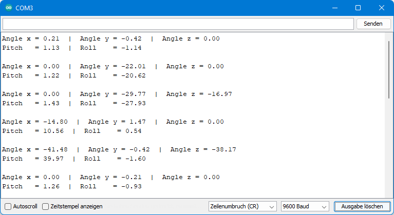
For the above output, I slowly rotated the ADXL345. I measured the values using simple tools (a protractor). For small to medium angles, the values called “Angle” are closer to reality, at large angles the pitch/roll method is better.
Example sketch 5: ADXL345_sleep.ino
To save power, you can send the ADXL345 to sleep. The function to do this (and to wake it up) is:
setSleep(true/false)
Sleep is interrupted by short waking phases. That cannot be stopped. But you can set the wake-up frequency to 1, 2, 4 or 8 Hz. To control the sleep mode together of the wake-up frequency, you can alternatively call the function with two parameters:
setSleep(true/false, frequency)
If you don’t retrieve new data too often, you won’t notice any difference to the permanent wake mode. Only when the frequency of your readings is greater than the wake-up frequency will you see the effect.
In the example sketch, 10 readings are retrieved in wake and sleep mode. I have set the wake-up frequency to one second, and the readings are sampled at 300 millisecond intervals. Here is the (shortened) sketch:
#include<Wire.h>
#include<ADXL345_WE.h>
#define ADXL345_I2CADDR 0x53  // 0x1D if SDO = HIGH

/* There are several ways to create your ADXL345 object:
 * ADXL345_WE myAcc = ADXL345_WE()                -> uses Wire / I2C Address = 0x53
 * ADXL345_WE myAcc = ADXL345_WE(ADXL345_I2CADDR) -> uses Wire / ADXL345_I2CADDR
 * ADXL345_WE myAcc = ADXL345_WE(&wire2)          -> uses the TwoWire object wire2 / ADXL345_I2CADDR
 * ADXL345_WE myAcc = ADXL345_WE(&wire2, ADXL345_I2CADDR) -> all together
 */
ADXL345_WE myAcc = ADXL345_WE(ADXL345_I2CADDR);

void setup(){
  Wire.begin();
  Serial.begin(115200);
  Serial.println("ADXL345_Sketch - Sleep");
  Serial.println();
  if(!myAcc.init()){
    Serial.println("ADXL345 not connected!");
  }

/* Insert your data from ADXL345_calibration.ino and uncomment for more precise results */
 // myAcc.setCorrFactors(-266.0, 285.0, -268.0, 278.0, -291.0, 214.0);

/* Choose the data rate         Hz
    ADXL345_DATA_RATE_3200    3200
    ADXL345_DATA_RATE_1600    1600
    ADXL345_DATA_RATE_800      800
    ADXL345_DATA_RATE_400      400
    ADXL345_DATA_RATE_200      200
    ADXL345_DATA_RATE_100      100
    ADXL345_DATA_RATE_50        50
    ADXL345_DATA_RATE_25        25
    ADXL345_DATA_RATE_12_5      12.5
    ADXL345_DATA_RATE_6_25       6.25
    ADXL345_DATA_RATE_3_13       3.13
    ADXL345_DATA_RATE_1_56       1.56
    ADXL345_DATA_RATE_0_78       0.78
    ADXL345_DATA_RATE_0_39       0.39
    ADXL345_DATA_RATE_0_20       0.20
    ADXL345_DATA_RATE_0_10       0.10
*/
  myAcc.setDataRate(ADXL345_DATA_RATE_50);
  Serial.print("Data rate: ");
  Serial.print(myAcc.getDataRateAsString());

/* Choose the measurement range
    ADXL345_RANGE_16G    16g
    ADXL345_RANGE_8G      8g
    ADXL345_RANGE_4G      4g
    ADXL345_RANGE_2G      2g
*/
  myAcc.setRange(ADXL345_RANGE_2G);
  Serial.print("  /  g-Range: ");
  Serial.println(myAcc.getRangeAsString());
  Serial.println();
}

void loop(){
/* Switch on (true) or switch off (false) sleep mode. Choose the wake up
    frequency:
    ADXL345_WUP_FQ_1  =  1 Hz
    ADXL345_WUP_FQ_2  =  2 Hz
    ADXL345_WUP_FQ_4  =  4 Hz
    ADXL345_WUP_FQ_8  =  8 Hz

    In this specific example you will see (provided you move the ADXL345) that
    in sleep mode the values are updated every third to fourth request. In awake
    mode the values are updated steadily. Sleep Mode saves significant power.
*/
  myAcc.setSleep(true, ADXL345_WUP_FQ_1);
  Serial.println("Measure in Sleep Mode:");
  doMeasurements();

  myAcc.setSleep(false);
  Serial.println("Measure in Normal Mode:");
  doMeasurements();
}


void doMeasurements(){
  for(int i=0; i<10; i++){
    xyzFloat g;
    myAcc.getGValues(&g);

    Serial.print("g-x   = ");
    Serial.print(g.x);
    Serial.print("  |  g-y   = ");
    Serial.print(g.y);
    Serial.print("  |  g-z   = ");
    Serial.println(g.z);

    delay(300);
  }
}
Output of ADXL345_sleep.ino
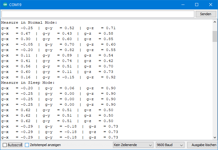
For the above output I moved the ADXL345 permanently. You can see that the values in normal mode are different for each query. In Sleep Mode, as expected, 3 to 4 values are identical.
Actually, it would be a good time to introduce the Auto Sleep mode next. But for the Auto Sleep mode we need interrupts and therefore we treat this topic first. I’ll come back to the Auto Sleep mode a little later.
Interrupt Features of the ADXL345
General information about the interrupt features
The ADXL345 distinguishes eight interrupts:
- Overrun: is triggered when unread data is overwritten, i.e. when the data rate is greater than the frequency of the data retrieval.
- Watermark: if the number of measured values in the FIFO buffer corresponds to the value defined in the FIFO control register (this will become clearer later).
- Free Fall: this is triggered when the acceleration values on all axes fall below a certain value for a certain time.
- Inactivity: when a limit of acceleration is exceeded on specified axes for a specified time.
- Activity: when a limit of acceleration is exceeded on specified axes.
- Single tap: an acceleration of a maximum duration that is above a certain limit.
- Double Tap: two peaks, both of which satisfy the single-tap conditions and also have a certain time interval between them.
- Data Ready: there is unread data.
You activate interrupts with the function setInterrupt(type, pin1/pin2). The first parameter is the interrupt type, with the second parameter you determine at which pin the interrupt is output. See the example sketches that use interrupts for a list of allowed parameters.
It is important to note that the interrupts for Overrun, Watermark and Data Ready are always enabled. So, you can’t disable them, just change the output pin. Default is INT1. You have to activate all other interrupts first. You deactivate them with deleteInterrupt(type).
In the interrupt register, in the case of an interrupt, the interrupt type is stored. Reading this register deletes the interrupt so that a new interrupt can be triggered. The function for this is readAndClearInterrupts(). It returns the interrupt type as a byte. How to “translate” this can be found in the library file ADXL345_WE.h. Alternatively, you check with checkInterrupt(source, type) for a specific type.
There is another general function, namely setInterruptPolarity(polarity). This sets whether the interrupt pins are active-low or active-high (default).
Example sketch 6: ADXL345_free_fall_interrupt.ino
First, let’s take a look at the Free Fall interrupt. In the example sketch, it is activated with setInterrupt(ADXL345_FREEFALL, INT_PIN_2) and assigned to INT2.
setFreeFallThresholds (0.4, 100) sets the acceleration limit to 0.4 g and the minimum duration for which it must be lower to 100 milliseconds. Limits for parameters and recommended values can be found in the example sketch. It is best to play around a little with the parameters to get to know this function better.
#include<Wire.h>
#include<ADXL345_WE.h>
#define ADXL345_I2CADDR 0x53  // 0x1D if SDO = HIGH
const int int2Pin = 2;
volatile bool freeFall = false;

/* There are several ways to create your ADXL345 object:
 * ADXL345_WE myAcc = ADXL345_WE()                -> uses Wire / I2C Address = 0x53
 * ADXL345_WE myAcc = ADXL345_WE(ADXL345_I2CADDR) -> uses Wire / ADXL345_I2CADDR
 * ADXL345_WE myAcc = ADXL345_WE(&wire2)          -> uses the TwoWire object wire2 / ADXL345_I2CADDR
 * ADXL345_WE myAcc = ADXL345_WE(&wire2, ADXL345_I2CADDR) -> all together
 */
ADXL345_WE myAcc = ADXL345_WE(ADXL345_I2CADDR);

void setup(){
  Wire.begin();
  Serial.begin(115200);
  pinMode(int2Pin, INPUT);
  Serial.println("ADXL345_Sketch - Free Fall Interrupt");
  Serial.println();
  if(!myAcc.init()){
    Serial.println("ADXL345 not connected!");
  }

/* Insert your data from ADXL345_calibration.ino and uncomment for more precise results */
  // myAcc.setCorrFactors(-266.0, 285.0, -268.0, 278.0, -291.0, 214.0);

/* Choose the data rate         Hz
    ADXL345_DATA_RATE_3200    3200
    ADXL345_DATA_RATE_1600    1600
    ADXL345_DATA_RATE_800      800
    ADXL345_DATA_RATE_400      400
    ADXL345_DATA_RATE_200      200
    ADXL345_DATA_RATE_100      100
    ADXL345_DATA_RATE_50        50
    ADXL345_DATA_RATE_25        25
    ADXL345_DATA_RATE_12_5      12.5
    ADXL345_DATA_RATE_6_25       6.25
    ADXL345_DATA_RATE_3_13       3.13
    ADXL345_DATA_RATE_1_56       1.56
    ADXL345_DATA_RATE_0_78       0.78
    ADXL345_DATA_RATE_0_39       0.39
    ADXL345_DATA_RATE_0_20       0.20
    ADXL345_DATA_RATE_0_10       0.10
*/
  myAcc.setDataRate(ADXL345_DATA_RATE_25);
  Serial.print("Data rate: ");
  Serial.print(myAcc.getDataRateAsString());

/* Choose the measurement range
    ADXL345_RANGE_16G    16g
    ADXL345_RANGE_8G      8g
    ADXL345_RANGE_4G      4g
    ADXL345_RANGE_2G      2g
*/
  myAcc.setRange(ADXL345_RANGE_2G);
  Serial.print("  /  g-Range: ");
  Serial.println(myAcc.getRangeAsString());
  Serial.println();

/* The parameters of the setFreeFallThresholds function are:
     - g threshold - do not choose a parameter which is too low. 0.3 - 0.6 g is fine.
     - time threshold in ms, maximum is 1275. Recommended is 100 - 350;
    If time threshold is too low, vibrations can be detected as free fall.
 */
  myAcc.setFreeFallThresholds(0.4, 100);

/* You can choose the following interrupts:
     Variable name:             Triggered, if:
    ADXL345_OVERRUN      -   new data replaces unread data
    ADXL345_WATERMARK    -   the number of samples in FIFO equals the number defined in FIFO_CTL
    ADXL345_FREEFALL     -   acceleration values of all axes are below the threshold defined in THRESH_FF
    ADXL345_INACTIVITY   -   acc. value of all included axes are < THRESH_INACT for period > TIME_INACT
    ADXL345_ACTIVITY     -   acc. value of included axes are > THRESH_ACT
    ADXL345_DOUBLE_TAP   -   double tap detected on one incl. axis and various defined conditions are met
    ADXL345_SINGLE_TAP   -   single tap detected on one incl. axis and various defined conditions are met
    ADXL345_DATA_READY   -   new data available

    Assign the interrupts to INT1 (INT_PIN_1) or INT2 (INT_PIN_2). Data ready, watermark and overrun are
    always enabled. You can only change the assignment of these which is INT1 by default.

    You can delete interrupts with deleteInterrupt(type);
*/
  myAcc.setInterrupt(ADXL345_FREEFALL, INT_PIN_2);

  attachInterrupt(digitalPinToInterrupt(int2Pin), freeFallISR, RISING);
  myAcc.readAndClearInterrupts();
}

void loop() {
  xyzFloat raw, g;
  myAcc.getRawValues(&raw);
  myAcc.getGValues(&g);

  Serial.print("Raw-x = ");
  Serial.print(raw.x);
  Serial.print("  |  Raw-y = ");
  Serial.print(raw.y);
  Serial.print("  |  Raw-z = ");
  Serial.println(raw.z);

  Serial.print("g-x   = ");
  Serial.print(g.x);
  Serial.print("  |  g-y   = ");
  Serial.print(g.y);
  Serial.print("  |  g-z   = ");
  Serial.println(g.z);

  Serial.println();

  if(freeFall==true){
    Serial.println("Aaaaaaaaah!!!!! - I'm faaaaallllling!");
    delay(1000);
    freeFall = false;
    /* by reading the interrupt register the interrupt is cleared */
    myAcc.readAndClearInterrupts();

    /* if you expect also other interrupts you can check the type. For this comment the previous line,
    and replace by the following four lines: */
    //byte intType = myAcc.readAndClearInterrupts();
    //if(myAcc.checkInterrupt(intType, ADXL345_FREEFALL)){
    //  Serial.println("FREEFALL confirmed");
    //}
  }

  delay(500);
}

void freeFallISR(){
  freeFall = true;
}
Example sketch 7: ADXL345_data_ready_interrupt.ino
I still have one example sketch for this part 1, then it’s half-time. Here we use the Data Ready interrupt to control the data output. First, I set the measuring frequency with setDataRate(ADXL345_DATA_RATE_0_20) to a slow 0.2 Hz.
The Data Ready Interrupt is always active. But to not interfere with the other “always-enabled” interrupts, I assigned it to INT2 with setInterrupt(ADXL345_DATA_READY, INT_PIN_2).
The rest is simple. The Data Ready interrupt triggers an interrupt on Arduino Pin 2. This is the signal for reading the measured values. After that, the interrupt is deleted and the next interrupt is expected.
#include<Wire.h>
#include<ADXL345_WE.h>
#define ADXL345_I2CADDR 0x53 // 0x1D if SDO = HIGH
const int int2Pin = 2;  // interrupt pin
volatile bool dataReady = false;

/* There are several ways to create your ADXL345 object:
 * ADXL345_WE myAcc = ADXL345_WE()                -> uses Wire / I2C Address = 0x53
 * ADXL345_WE myAcc = ADXL345_WE(ADXL345_I2CADDR) -> uses Wire / ADXL345_I2CADDR
 * ADXL345_WE myAcc = ADXL345_WE(&wire2)          -> uses the TwoWire object wire2 / ADXL345_I2CADDR
 * ADXL345_WE myAcc = ADXL345_WE(&wire2, ADXL345_I2CADDR) -> all together
 */
ADXL345_WE myAcc = ADXL345_WE(ADXL345_I2CADDR);

void setup(){
  Wire.begin();
  Serial.begin(115200);
  pinMode(int2Pin, INPUT);
  Serial.println("ADXL345_Sketch - Data Ready Interrupt");
  Serial.println();
  if(!myAcc.init()){
    Serial.println("ADXL345 not connected!");
  }

/* Insert your data from ADXL345_calibration.ino and uncomment for more precise results */
  // myAcc.setCorrFactors(-266.0, 285.0, -268.0, 278.0, -291.0, 214.0);

/* Choose the data rate         Hz
    ADXL345_DATA_RATE_3200    3200
    ADXL345_DATA_RATE_1600    1600
    ADXL345_DATA_RATE_800      800
    ADXL345_DATA_RATE_400      400
    ADXL345_DATA_RATE_200      200
    ADXL345_DATA_RATE_100      100
    ADXL345_DATA_RATE_50        50
    ADXL345_DATA_RATE_25        25
    ADXL345_DATA_RATE_12_5      12.5
    ADXL345_DATA_RATE_6_25       6.25
    ADXL345_DATA_RATE_3_13       3.13
    ADXL345_DATA_RATE_1_56       1.56
    ADXL345_DATA_RATE_0_78       0.78
    ADXL345_DATA_RATE_0_39       0.39
    ADXL345_DATA_RATE_0_20       0.20
    ADXL345_DATA_RATE_0_10       0.10
*/
// Choose a low frequency to showcase the data rate controlled output
  myAcc.setDataRate(ADXL345_DATA_RATE_0_20);
  Serial.print("Data rate: ");
  Serial.print(myAcc.getDataRateAsString());

/* Choose the measurement range
    ADXL345_RANGE_16G    16g
    ADXL345_RANGE_8G      8g
    ADXL345_RANGE_4G      4g
    ADXL345_RANGE_2G      2g
*/
  myAcc.setRange(ADXL345_RANGE_2G);
  Serial.print("  /  g-Range: ");
  Serial.println(myAcc.getRangeAsString());
  Serial.println();

  attachInterrupt(digitalPinToInterrupt(int2Pin), dataReadyISR, RISING);

/* Default Interrupt Pin Polarity is active high. Change if you like */
  // myAcc.setInterruptPolarity(ADXL345_ACT_LOW);

/* You can choose the following interrupts:
     Variable name:             Triggered, if:
    ADXL345_OVERRUN      -   new data replaces unread data
    ADXL345_WATERMARK    -   the number of samples in FIFO equals the number defined in FIFO_CTL
    ADXL345_FREEFALL     -   acceleration values of all axes are below the threshold defined in THRESH_FF
    ADXL345_INACTIVITY   -   acc. value of all included axes are < THRESH_INACT for period > TIME_INACT
    ADXL345_ACTIVITY     -   acc. value of included axes are > THRESH_ACT
    ADXL345_DOUBLE_TAP   -   double tap detected on one incl. axis and various defined conditions are met
    ADXL345_SINGLE_TAP   -   single tap detected on one incl. axis and various defined conditions are met
    ADXL345_DATA_READY   -   new data available

    Assign the interrupts to INT1 (INT_PIN_1) or INT2 (INT_PIN_2). Data ready, watermark and overrun are
    always enabled. You can only change the assignment of these which is INT1 by default.

    You can delete interrupts with deleteInterrupt(type);
*/
  myAcc.setInterrupt(ADXL345_DATA_READY, INT_PIN_2);
  myAcc.readAndClearInterrupts();
}

/* In the following loop there is only one interrupt type that can occur on INT2.
    In cases where you expect more candidates, you can check as follows:
        uint8_t intType = myAcc.readAndClearInterrupts();
        if(myAcc.checkInterrupt(intType, ADXL345_DATA_READY)){
          Serial.println("DATA READY confirmed");
        }
*/
void loop() {
  // you see here is no delay to control the output rate
  if(dataReady==true){
    xyzFloat g;
    myAcc.getGValues(&g);
    // dataReady = false; // uncomment, if you want capture next interrupts

    Serial.print("g-x   = ");
    Serial.print(g.x);
    Serial.print("  |  g-y   = ");
    Serial.print(g.y);
    Serial.print("  |  g-z   = ");
    Serial.println(g.z);

    dataReady = false; // comment, if you have set dataReady to false before
  }
}

void dataReadyISR(){
  dataReady = true;
}
Outlook
In the next article, we will come to the example sketches for
- Activity / Inactivity
- Auto Sleep Mode
- Single / Double Tap
- Various FIFO modes
Acknowledgement
The utensils I attached to the ADXL345 module in the post image are from the image of a Swiss Army Knife by Clker-Free-Vector-Images on Pixabay.
I would like to thank Adafruit for publishing the Fritzing scheme of their ADXL345 module.
Good morning Wolfgang,
I’ve been using your ADXL345 library with an Arduino Nano 33 BLE board, and it has always worked flawlessly.
I’m very satisfied and I thank you for that.
Now I’m developing a similar custom board and writing the firmware in the Nordic nRF Connect / Zephyr environment.
I wanted to ask you: in your opinion, does it make sense to try compiling it in the Nordic environment using C or C++, or do you think it would be too demanding and it’s better to follow a different approach?
Thank you!
Paolo S.
Hi Paolo,
sorry I am lacking experience with Nordic nRF Connect / Zephyr environment. Therefore, I am unable to provide a reliable answer.
Wolfgang
A great library as your other ones have been.
One problem I am having is that if set the data rate as 100Hz I can detect taps but if I set to 200Hz I dont seem to be able to. Any ideas? The data sheet isn’t very clear on how tap detect works but seems to imply that tap detection is independent of the date rate.
The adx343 is much more common and cheaper now. Your library seems to work fine with it
I am using the chip without interrupts and with the fifo. I poll the date ready bit and then empty the fifo. This works but it is more tricky if the want to detect other events (tap, activity…) you have remember the status while you empty the fifo. Anyway I have written am example of this which I could send you if you are interested.
David Liddell
Hi David, in your comment, you mention the ADXL345, but it’s not clear whether the tap problem occurred when using an ADXL345 or an ADXL343. I have just tried the double tap example sketch without any changes using an ADXL345 and it works fine. The data rate is 200 Hz. Have you tried this sketch unchanged? If you have changed the tap parameters, maybe they do not fit to the data rate? I can’t comment on the ADXL343 since I do not have one yet. It’s on my to-do list, but this list is quite long. Maybe I find some time after completing my next article. Your comment is a good reminder!
I am interested in your example which works without interrupt (wolfgang.ewald@wolles-elektronikkiste.de). Perhaps I can take a look when I am diving into the ADXL 343. Not before because I need to stop doing too many different things in parallel.
Wolfgang
hi,
i need some help to measure 16G range with full resolution mode, i am using your lib, but the doubt is after changing it 16G in the set range, i am getting raw values up to 255 only.
another doubt is in the 2G range, the raw value is +255 to -255, after conversion, it is giving only +1 to -1. it has to give as -2 to +2g correct?
Hi, I don’t know what’s wrong on your side. I have just tried the example sketch ADXL345_basic_data.ino and provides the expected values. In the 2 g range, the resolution is 10 bits which means the raw value range is from -2^9 to +2^9 – 1 which is -512 to +511. For 4 g: resolution = 11 bits, which means -2^10 to +2^10 – 1 or -1024 to +1023. And so on for 8 and 16 g.
Of course, to obtain values beyond +/- 1 g, you have to apply such accelerations, e.g. by shaking the module. Since the force of gravity is only 1 g, you will not see any higher values if you only rotate the module around its axis.
“Thank you very much for the great tutorial.
I’m interested in using the ADXL345 module standalone to detect free-fall conditions. The module’s interrupt pin (pin 2) goes high when free-fall is detected. Can I use the ADXL345_WE library with an Arduino to configure the module for this specific application and process the interrupt signal?”
You can’t use the ADXL345 standalone. This is no feature I could add to my library. The reason is that the ADXL345 will “forget” all settings you applied after you re-power it. The register will go back to default values. So, you will always need a microcontroller to apply the settings you need. It would be cool if the ADXL345 had some kind of flash memory to remember settings, but that’s not the case.
Hi Wolfgang, thanks a lot for your library.
One question. Using the I2C connection can I get a sampling rate of 3200 Hz? Or only with SPI?
Hi Emanuel,
the data sheet says:
“Due to communication speed limitations, the maximum output
data rate when using 400 kHz I2C is 800 Hz and scales linearly with
a change in the I2C communication speed.”
And:
“Use of the 3200 Hz and 1600 Hz output data rates is only
recommended with SPI communication rates greater than or
equal to 2 MHz. The 800 Hz output data rate is recommended
only for communication speeds greater than or equal to 400 kHz,
and the remaining data rates scale proportionally. “
When you try SPI / 3200 Hz and you display the values via Serial.print(), then Serial.print() will be the bottleneck, even at a baud rate of 115200. Many users try this and are disappointed.
Regards, Wolfgang
Thank you very much for your reply.
Does this library work with esp8266? I tried to use it but the D8 pin (GPIO15) gives me problems when loading the code.
Hi, this is really an interesting one. I have just tried it on an WEMOS D1 mini board using D8 as CS pin. And I can confirm that the upload does not work. Then I tried to upload a simple blink sketch while I kept the same connections. It also did not work. I disconnected D8, uploaded the ADXL345 SPI sketch, connected D8 and it worked. Then did a reset and it didn’t work. Finally, I chose D4 as CS pin and with this upload and reset worked.
I found the issue: D8 needs to be at LOW level when the ESP8266 reboots. But the CS Pin of the ADXL345 is HIGH. Therefore, no reset and no upload. This is nothing I can influence by code. The module has a pull-up resistor attached to CS, or at least this one:
http://wiki.sunfounder.cc/index.php?title=File:ADXL345_2.png
So, the options you have are:
1) Choose a different CS pin, D4 worked for me
2) Keep D8 as CS and attach a pull-down resistor. Everything worked on my side with a 10 kohms resistor. But this is not a nice solution.
3) Remove the pull-up resistor on the module.
Thank you for raising this! I will add this useful information.
Thank you very much Wolfgang, I can confirm that your library is the only one that works on esp8266 via SPI.
One last question, I removed the resistor R4 and it works like a charm. I have another adxl345 that looks like the following image, what resistor should I remove in this case?
https://components101.com/sites/default/files/components/ADXL345-Accelerometer-Module.jpg
It is the one next to CS. I have such a module and just tried it. You need to be a little careful to not destroy the line between the CS pin of the module and the CS pin of the ADXL345 IC when removing the resistor.
I tested the module without removing the resistor and it works. I think I won’t remove it to avoid damaging it. Thanks a lot Wolfgang
splendid work!, thanks for sharing the effort.
Thank you!
Nice stuff! As mentioned in another comment, there are issues with ESP32 and these interrupts:
I found, running ADXL345_WE on ESP32, I needed to clear the interrupt after it had been set up, for it to function properly. Luckily, I had read about that issue somewhere else otherwise I wouldn’t have figured it out. Depending on baud rate and sample rate this error occurs more or less often.
Specifically, call readAndClearInterrupts(). I currently monitor the loop and if no interrupts have been received for a second, I clear it, but I could probably fix it at setup – and it should only ever need to be performed once.
The issue is that the first interrupt is triggered before we have a listener configured (sounds like an ESP32 bug). Since no-one retrieves the interrupt, no more interrupts are triggered.
Slower sample rates trigger this issue more seldom, probably because the interrupt is properly set up before the first interrupt occurs.
Also, in the interrupt example, you set dataReady to false too late in the process. You should probably clear it immediately to be ready for one more data read, should it occur during the serial print.
if(dataReady==true){
xyzFloat g = myAcc.getGValues();
Serial.print(“g-x = “);
Serial.print(g.x);
Serial.print(” | g-y = “);
Serial.print(g.y);
Serial.print(” | g-z = “);
Serial.println(g.z);
dataReady = false;
}
cheers and thanks,
mattias
Hi, this is very helpful. I will add the readAndClearInterrupt(). But I won’t change the position of dataReady=false; I know what you mean, but I find it more logic to wait for the newest data after having displayed the values. Thanks, Wolfgang
Regarding the position of dataReady: certainly your choice.
To clarify my point, I would move it to after “xyzFloat g = myAcc.getGValues();” but before the print statements. The meaning being “I’ve received the current data and is ready for more” since the data has been read. If the print part (or any additional logic like filtering and integration) takes too long, we might miss that a new piece of data has been received. If any new data arrives during this process, it will be lost. I realize this isn’t a big problem in most situations, but in data gathering, every sample is/can be important (if you’re for instance are integrating to a velocity).
In some cases you might perform processing every N data samples – processing that takes just long enough that you miss one sample. If you move the dataReady, you’ll avoid *some* of these issues. On the other hand, if your data processing step takes too long to process the incoming data, you’re already riding a thin line…
Anyway, awesome library, much thanks!
Thanks, yes, I had understood. Still I see it slightly different. It depends on what you want. I have now added another dataReady() after xyzFloat g = myAcc.getGValues(); but I have commented it out and added a comment. Thank you again!!
Hi Wolfgang!
Thank you for all the efforts you are making to make Arduino usage better. I’ve one request which is about ADXL 345 used with Arduino UNO R3 in 4-wire SPI. I’ve used your library and connections as you suggested and tried to implement the suggestions from discussion part also. Unfortunately, I could not achieve desired output of 1600 – 3200 Hz. I’m using ADXL 345 for simple vibration monitoring where I need to collect at least 1600 data per axis in one second.
Will you post whole code with these implementations either in new post or in comment here, so that your readers will be benefitted and be thankful?
Hi Surbana,
if you set a data rate of 3200 Hz, the ADXL345 will measure at that rate. And using SPI you will also be able to read at that rate. But if you are trying to display at that rate on the serial monitor you will fail because the bottleneck is the slow Serial.println function. If you increase the baud rate you will increase the output rate on the serial monitor but 3200 Hz will be hardly achievable. What might work is to write at that speed to an SPI EEPROM or to a fast SDHC card or, if you use an ESP32, to write to the flash with SPIFFS or LittleFS. But I haven’t tried that. Hope that helps.
Hi, is there a way to use the ADXL345 without initializing it fully? The reason is that I’m using an ESP32 which goes to setup() every time it goes to sleep. All variables are lost except basics that can be persisted using the RTC_DATA_ATTR qualifier (e.g. RTC_DATA_ATTR uint16_t wakeCount = 0;). The wakeup reason can be found (e.g. which trigger pin, i.e. from the ADXL345). ideally, i’d like to init() the accelerometer at bootup ONLY, then on subsequent uC wakeups just restart wire, etc. *not* write registers to the ADXL345. Is there a way to do it without modifying the library? Many thanks!
Hi, if you check the reset cause after the reset and you find it’s a wake up, then you can of course omit the init() function. But the init() function ensures a defined starting conditions. There are at a few things you would then have to define “manually” in a kind of alternative init() function. In particular you need to have a defined offset values for the acceleration and the angles. For this, you have setting functions available. You also need to define the range factor. It’s not public, but for this you can read the range with getRange and then write it back with setRange. Then the rangeFactor will then be defined. So, it could work, but you’ll need to try a bit.
Hello , I am seeking guidance on how to utilize the default HSPI pins for the ESP32 in order to operate the ADXL345 in SPI mode. Specifically, I am uncertain about the process of passing a SPI object, and would appreciate any advice on this matter.
Hi Mark,
how to use SPI is shown in the example sketch ADXL345_SPI_basic_data. You pass the SPI object as a reference (with “&”). This line creates the ADXL345_WE object when using the standard SPI (VSPI) interface:
ADXL345_WE myAcc = ADXL345_WE(&SPI, CS_PIN, spi);
Here, I have described how to use HSPI:
https://wolles-elektronikkiste.de/en/programming-the-esp32-with-arduino-code#SPI
In short:
SPIClass SPI_2(HSPI); // creates the object SPI_2 which uses HSPI
ADXL345_WE myAcc = ADXL345_WE(&SPI_2, CS_PIN, spi); // creates the ADXL345_WE object which uses SPI_2
That’s all! Good luck.
Hi Wolfgang,
I have one question which I tried researching, but I had no luck.
In regards to the measurement range, the +/- 2g utilizes 10 bits while +/-16g utilizes 13 bits.
In that case would the +/- 2g have max value of 255 and min value of -255, while the +/- 16g would have the max value of 8191 and min value of -8191, or am I completely misunderstanding this ?
Hi Damian, the ADXL345 has two different modes, the fixed 10-bit resolution mode and the full resolution mode.
In the full resolution mode, as you rightly say, the +/- 2g range utilizes 10 bit, which means -2g is -2^9 (=-512) and +2g is 2^9 – 1 (= +511) because it’s a signed 10 bit range. In the +/- 4g range 11 bit are utilized, i.e. -4g is -2^10, and so on until the +/- 16g range where the values go from -2^12 (= -4096) to +2^12 – 1 (= +4095). So you are right regarding the bits, only the calculations of the resulting ranges were wrong.
In the fixed 10-bit mode, which you can activate with setFullRes(false) when using my library, 10 bits are use for all ranges. But I am not really sure why one would choose that mode.
You can also find this in the data sheet (https://www.analog.com/media/en/technical-documentation/data-sheets/adxl345.pdf). Reading data sheets is not much fun, but this is one of the better understandable ones.
How to reset the ADXL345?
// There is no reset pin or reset instruction for the ADXL345, therefore use the default values from the Register Map.
// See pg 23 of the datasheet, https://www.analog.com/media/en/technical-documentation/data-sheets/adxl345.pdf.
void ADXL345Reset() {
myAcc.writeRegister(myAcc.ADXL345_DEVID, 0xE5); // 0b1110 0101 = 0xE5
// registers 0x01 to 0x1C: reserved
// registers 0x1D (29) to 0x39 (57) = 0x00 except for two.
for (int i = 0x1D; i <= 0x39; i++) {
if (i == myAcc.ADXL345_BW_RATE) { // BW_RATE is 0x2C.
myAcc.writeRegister(i, 0x0A); // default: 0b0000-1010 = 0x0A
} else if (i == myAcc.ADXL345_INT_SOURCE) { // INT_SOURCE is 0x30
myAcc.writeRegister(i, 0x02); // default: 0b0000-0010 =0x02
} else { // all the rest have values 0.
myAcc.writeRegister(i, 0x00);
}
}
}
Thank you. It’s a shame that the ADXL345 has no reset pin or reset bit. That’s why I set what I consider to be the relevant registers back to default as part of the init() – function. But it’s a good idea to implement a separate function for this. I will do this as part of the next update of the library. Best wishes, Wolfgang
Thank you for this library.
I’m using an Adafruit Feather RP2040 and the Arduino Raspberry Pi Pico/RP2040 package provided by Earle F. Philhower III. I’m connecting the Feather RP2040 to an Adafruit ADXL345 board via a STEMMA QT I2C cable.
The Feather RP2040 board puts the STEMMA QT pins on RP2040 pins 2 and 3, i.e., Wire1.
In order to get the ADXL345_basic_data.ino sketch to work with this combination of things, I had to use:
ADXL345_WE myAcc = ADXL345_WE(&Wire1);
and
Wire1.begin(); instead of Wire.begin(); in Setup().
Not sure why the second change was necessary (Wire1.begin()).
Hi – great that you found the solution. I don’t have much experience with the Feather RP2040. I think I would have had to search quite some time to find out that you need to pass Wire1. But I think the second change (Wire1.begin()) makes sense: If you use the Wire1 object, then Wire.begin() has no effect on Wire1.
the power use of the device can be drastically reduced by removing the power regulator (just rip it out with needle-nose pliers, tweezers or simply a screwdriver. then connect the board’s Vcc to the chip’s Vdd_io or anything else connected to it. Vdd_io is the pin closest to the “P” of the “PHIL” on the chip. i can send you a diagram if you want, i made one.
Thanks, very interesting – and yes, please send the diagram, then I can publish it in the comments. Send it to: wolfgang.ewald@wolles-elektronikkiste.de.
Hi Mahesh,
thanks for that!
Can you tell us how much you have reduced the power consumption? On my modules there is a LD3985 (Label: 4A2D) voltage regulator. According to the data sheet it consumes 85 µA when there is no load.
And one hint for all people who try the same: You need to consider that the supply voltage for the ADXL345 is 2.0 to 3.6 volts!
Hi Wolfgang, thank you for your hard work and excellent documentation on this library.
Your library is one of the easiest to use for this accelerometer.
My plan is to use the ADXL345 to detect activity and inactivity as part of a bicycle GPS tracker. When the bicycle is stationary, I will put the microcontroller to sleep and wake it up using an activity interrupt. I built a prototype using your library and it works well when placed flat on a table surface. My problem is, the “resting” position is when the bicycle is leaning to one side on its stand, meaning, at that position, the ADXL345 is at an angle.
This seems to cause the activity interrupt to fire continuously, as I understand there is a force constantly measured on an axis.
Am I misunderstanding how this activity interrupt will work? Is there a way to use calibration to “calibrate” the ADXL345 that the stationary (but not level, as the bicycle is leaning on its stand) position of the sensor is actually able to produce an inactivity interrupt, and moving from that position will produce an activity interrupt?
Hi Willem, did you choose the AC mode in setActivityParameters? If you do so then the interrupts should only fire if the delta to the g-values are exceeded relative to the ones that were detect when you set up the interrupt. Horrible sentence – I hope you understand what I mean. Regards, Wolfgang
Hi Wolfgang
I did not – I was using DC mode.
Your sentence is fine, and I clearly see why this was not working. I do see that this is in fact documented, but perhaps it is good that it is in the comments as well, for anyone else facing this problem.
For anyone else facing the same problem:
setActivityParameters(mode, axes, g-threshold)
DC: the limit (threshold) applies absolutely.
AC: the limit is the delta to the starting value
Thank you for taking the time to answer and for providing such a nice piece of software
Hi, I have tried both connections in the library by my xyz value still reads 00.
I am using MKR GSM 1400 as my board. any help with the connection? I’m trying to build a GPS tracker that send an sms with device location.
Hi, some questions which might help to solve the problem: have you applied one of the example sketches without any changes? Did the sketch compile without any warning? When you set up the I2C connection and run an I2C scanner sketch, is the ADXL345 visible? Have you connected the CS pin? And finally: have you tried another library?
I have not tried the MKR GSM 1400 with my library, but if there was a compatibility issue I would expect a compiler error rather than zero readings.
Hi, so I ran the scanner sketch, and this was the output.
Scanning in standard mode (100 kHz):
0x42
0x60
0x6B
Scanning in fast mode (400 kHz):
0x42
0x60
0x6B
Not quite sure what it means.
But I did try the Adafruit one and run the sensor test, but I was unlucky because no ADXL345 detected. My conclusion module is damaged or fake, I will go ahead and order another one.
Thank you for your help
Strange result from the scanner. I would expect 0x53 or 0x1D. No idea why you detect three I2C addresses. I would also try another module. Good luck!
I just go a new module and after running all the test I am still getting the same result. what would you suggest going about? because I am stuck now. I want to make use of ADXL345 because it has INT1 and INT2 together with the interruption library.
I meant the ADXL345_activity_inactivity library
Can you run the I2C scanner again? I found out that 0x60 and 0x6B are detected, even if no I2C device is detected. It must be internal I2C devices on the Arduino Board. When I connect the ADXL345, then I detect 0x53 and the other two addresses.
The ADXL345 has two I2C addresses to choose from, 0x53 and 0x1D. You should get 0x53 if SDO is unconnected or connected to GND. You should detect 0x1D if SDO is connected to VCC. Please try. You can change the SDO connection while the scanner is running.
It is very strange that you detected 0x42. According to the datasheet:
https://www.analog.com/media/en/technical-documentation/data-sheets/ADXL345.pdf
only 0x53 and 0x1D are available. If you detect 0x42 again, then try and change the I2C address in example sketches. Maybe it works, maybe it doesn’t. If you don’t detect 0x1D or 0x53 as I2C it would mean that you don’t have an original ADXL345. What exactly is the label on the IC on your ADXL345 board? On mine it’s 345B as you can see on the photos in my article.
By the way: 42 is the answer to the Ultimate Question of Life, the Universe, and Everything, but not in hexadecimal ;-).
I have updated the library. There shouldn’t be any incompatibility with SAMD Boards anymore. At least it compiles. But I don’t think this is related with the I2C issues you have. The addresses you detect are not the original ADXL345 addresses.
Hi, I have just tried it myself and indeed there is an issue. The SAMD Microcontrollers do not like the statement “setDataMode(SPI_MODE3);”. I only ask myself why it compiled at all on your side!?
I can’t solve the issue easily, otherwise I would do it immediately. But there is a fix which allows you to work at least with I2C on MKR GSM 1400. All you have to do is to go into ADXL345_WE.cpp and comment or delete line 62:
_spi->setDataMode(SPI_MODE3);
Save it and I2C will work. I have just tested with a MKR GSM 1400. I will work on a better solution, but this will take time.
Connection is easy:
VCC (3.3 V) to VCC
GND to GND
SDA (Pin 11) to SDA
SCL (Pin 12) to SCL
CS to VCC
If you use interrupts then connect INT2 to pin 0, 1, 4, 5, 6, 7 or 8).
Thank! I had that line commented already, I am wondering which sketch you tried on because I have the connection set up as you mention but my readings is still 000 all axis or there might be an issue with the accelerometer, I don’t know. What do you think? Thanks!
I took the ADXL345_basic_data.ino without any changes and with the wiring like I described. Strange things happen! Of course, modules can be damaged or sometimes there are fake models. But before you order new modules I think there other options first. What if you try another library? There is one from Seeed Studio or the one from Adafruit. It’s quick to install them and try an example sketch.
And if you run a scanner sketch like the one I have published here:
https://wolles-elektronikkiste.de/en/i2c-scanner?lang=en
Do you get a response?
The method measureAngleOffsets calibrates the board, however is it possible to get those values (store them) and read the offset values from e.g. flash and provide them to the library? The idea is: you install the board on e.g. a surface… turn it off and after a week you turn it on to see if the surface moved… press a button to calibrate…store the values… turn off the device…
Hi, I have just added a getAngleOffsets() and setAnglesOffsets() function. To get it you add e.g.:
xyzFloat angleOffsets = myAcc.getAngleOffsets();
Serial.println(“Angle Offsets: “);
Serial.print(“x: “); Serial.println(angleOffsets.x);
Serial.print(“y: “); Serial.println(angleOffsets.y);
Serial.print(“z: “); Serial.println(angleOffsets.z);
I didn’t add a function to store the values. This is up to you. You could use the EEPROM or an SD-Card.
In order to set the offsets you can add:
xyzFloat angleOffsets = {-2.18, 5.04, 88.9}; // x-Offset = -2.18; y-Offset = 5.04; z-Offset = 88.9;
myAcc.setAngleOffsets(angleOffsets);
or the long version:
xyzFloat angleOffsets;
angleOffset.x = -2.18;
angleOffset.y = 5.04;
angleOffset.z = 88.9;
myAcc.setAngleOffsets(angleOffsets);
I have done this quickly without changing example sketches or the list of functions. This will be done at a later stage.
The new version is 2.1.3 and is available on GitHub. It usually takes a day until the Arduino Library Manager finds the new version.
Hope that helps.
Thank you very much… I’ve looked what you did and it should do the trick…
I am storing data to the memory of the ESP32 after I get it using your methods and read it from it again and assign it…
During the below test the sensor is on a stable desk and not moved.
When I calibrate and save the offset I get:
Saved Angle Offsets:
x: 0.31
y: -0.63
z: 90.00
Measured values:
cAngle x = 0.00 | cAngle y = 0.00 | cAngle z = 0.00
cAngle x = 0.00 | cAngle y = -0.21 | cAngle z = 0.00
cAngle x = -0.21 | cAngle y = -0.21 | cAngle z = 0.00
When I load the offset an assign it , I get:
Load Angle Offset:
x: 0.31
y: -0.63
z: 90.00
Measure values:
cAngle x = 0.10 | cAngle y = -0.63 | cAngle z = 90.00
cAngle x = 0.31 | cAngle y = -0.63 | cAngle z = 90.00
cAngle x = 0.52 | cAngle y = -0.63 | cAngle z = 90.00
The measured values (difference) with loaded offset vs. offset after calibration is very small but should not it be the same since nothing really changed on the setup…
Interesting find is that after I loaded the values… do another calibration to get the offset… the exact same values come back:
Saved Angle Offsets:
x: 0.31
y: -0.63
z: 90.00
Measured values:
cAngle x = 0.00 | cAngle y = 0.00 | cAngle z = 0.00
cAngle x = 0.00 | cAngle y = -0.21 | cAngle z = 0.00
cAngle x = -0.21 | cAngle y = -0.21 | cAngle z = 0.00
Would love to hear your thoughts.
I have just tried it again. When I apply the getAnglesOffset() function like I have described I get something like this:
Angle Offsets:
x: -1.77
y: -3.36
z: 90.00
Raw-x = 1.00 | Raw-y = -9.00 | Raw-z = 227.00
g-x = -0.03 | g-y = -0.05 | g-z = 1.05
Angle x = -1.77 | Angle y = -2.94 | Angle z = 90.00
cAngle x = 0.00 | cAngle y = 0.42 | cAngle z = 0.00
Orientation of the module: z up
Then I apply the offsets and get this:
Raw-x = 0.00 | Raw-y = -10.00 | Raw-z = 239.00
g-x = -0.03 | g-y = -0.05 | g-z = 1.10
Angle x = -1.98 | Angle y = -3.15 | Angle z = 90.00
cAngle x = -0.21 | cAngle y = 0.21 | cAngle z = 0.00
Orientation of the module: z up
This is what I expected and what you would like to have, right? Not sure what’s wrong on your side. When you apply the offsets you have to take out the calibration of course. Or something’s wrong with the order. I send you the sketches, then you can compare.
Hi
I’m using MKR GSM 1400 as my main board . I have tried to upload example sketches on to the board but it has not been successful because I’m getting these error which I don’t really understand. Some help will be so much useful
This is the ERROR:
C:\Users\lenovoYoga\Documents\Arduino\libraries\ADXL345_WE-main\src\ADXL345_WE.cpp: In member function ‘bool ADXL345_WE::init()’:
C:\Users\lenovoYoga\Documents\Arduino\libraries\ADXL345_WE-main\src\ADXL345_WE.cpp:62:15: error: ‘arduino::SPIClass {aka class arduino::HardwareSPI}’ has no member named ‘setDataMode’
_spi->setDataMode(SPI_MODE3);
^~~~~~~~~~~
exit status 1
Error compiling for board Arduino MKR GSM 1400.
Thank you
Hi,
this means that the setting of SPI modes via setDataMode() is not implemented for the MKR GSM 1400. I just tried it and get the same error for all SAM based boards. I just tried to take this command out and then it compiles. But compiling does not guarantee that it works properly. I have only chosen the MKR GSM 1400 as board in the IDE and compiled. So I did not really upload and test.
You could do me a favour: please go into ADXL345_WE.cpp and comment line 62:
_spi->setDataMode(SPI_MODE3);
Just with: //
Save it and compile your sketch. There should be no error anymore. But I am keen to know if the then ADXL345 works properly. If yes, I can fix this easily, if no I have to invest some more time.
Hello Mr. Wolfgang,
I have seen that you did a great job by implementing the SPI library. I just wanted to ask you if you would implement a function to change the SPI frequency (up to 5 MHz).
Thank you very much.
Regards
Andrea
Hi Andrea, that is on my to do list. I hope I can do this within the next few weeks. I am careful with promising too much. Regards, Wolfgang
HI,
thank you for your great work it helpped me alot.
so i am using an adxl345 mems sensor with an esp32 board.
I have tried your ADXL345_basic_data skitch and it worked for me so the connections are all okay.
i am trying to use the ADXL345_data_ready_interrupt skitch i just copied it and past it in IDE.
I am only getting once sensor data when i upload the code at the first begging and after that i dont recieve anything.
I also have connected a saleae logic analayzer to the I2C bus but i dont see anything on the scl or on the sda lines.
Could you please tell me why is this happening. i think the interrupt pin is not going low at all
Hi, I have just tried it with an esp32 development board and the ADXL345_data_ready_interrupt.ino sketch without any modification. I works on my side Every few seconds I get new data. Have you connected the Int2 Pin (not Int1!) of the ADXL345 with GPIO2 of the ESP32? If you have done this and it still does not work I would try to change to another GPIO pin. GPIO2 is one of the strapping pins which might cause issues when connected during boot. It can vary depeneding on the esp32 board type if you have ab issue or not with this, Hope this helps.
Thank you for your reply.
I have now connected int2 (ADXL345 side) to pin number 4 (ESP32) and adjusted the line in the skitch to
const int int2Pin = 4;
but i dont get anything as before
anyother ideas that will help maybe?
Thank you again.
I have tried GPIO5 and now its working. Thank you very much.
But as soon as i increase the dataRate above 12.5 Hz i don’t get anything
I am trying to set the datarate to 3200
Command: myAcc.setDataRate(ADXL345_DATA_RATE_3200);
Do you have maybe an explanation for me?
i also have tried it with 25 Hz 800 Hz and 100 Hz but its not working. It works only for low datarates
Thank you again for helping me
Hi, in this case the limiting factor is the slow Serial.println command in conjunction with the low Baudrate of 9600. If you increase the Baudrate to 115200 you will be able to apply higher rates, but surely not up to 3200 Hz. The ADXL345 is able to measure at this rate, but you can’t print at that rate.
You can avoid that the sketch stops by moving:
dataReady=false
directly after:
if(dataReady==true){
But again, still the output rate will be limited by the speed of the Serial.print command.
thank zou for zour reply
actuallz i dont need the serial print lines so i commented them all. I have increased the Baudrate to 2000000 but i still cant get any data in the i2C bus (monitored with the logic analyzer) with any frequency higher than 400 Hz.
Is there anyway to get it work at 3200 Hz?
Thank you very much
It is possible with SPI instead of I2C – sorry I have not implemented that (yet).
The data sheet says:
“Due to communication speed limitations, the maximum output
data rate when using 400 kHz I2C is 800 Hz and scales linearly with
a change in the I2C communication speed.”
And:
“Use of the 3200 Hz and 1600 Hz output data rates is only
recommended with SPI communication rates greater than or
equal to 2 MHz. The 800 Hz output data rate is recommended
only for communication speeds greater than or equal to 400 kHz,
and the remaining data rates scale proportionally. “
really thank you very much for your reply
I have used the SparkFun_ADXL345 library to commuicate with SPI and it has worked.
Connections:
CS -> 5
CLK -> 18
MISO/SDO -> 19
MOSI/SDA -> 23
Vin -> 3V3
GND -> GND
INT2 -> PIN4
I have tried to use again the DataReady interrupt but its unfortunatlly not working. I think i am missing something with the initialization.
attachInterrupt(digitalPinToInterrupt(int2Pin), dataReadyISR, RISING);
adxl.setInterruptLevelBit(0);
adxl.setInterruptMapping(ADXL345_DATA_READY, ADXL345_INT2_PIN);
adxl.setInterrupt(ADXL345_DATA_READY, 1);
I can send you my whole code if you want to help me.
Hi, I already spend so much time on my own libraries and blog – so I can’t spend additional time on other ones.
But I will try to add SPI functionality to my AXL345 library this weekend (I hope I don’t promise too much). I wanted to do this anyway sooner or later. If you can wait for one or two days, I will inform you when it’s updated on GitHub.
perfect
then i will wait
Thank you agian
Done! Hope it’s working on your side. I have not tried it yet with an ESP32.
….and after some time I have now added a function to select the SPI clock speed.
I found, running ADXL345_WE on ESP32, I needed to clear the interrupt after it had been set up, for it to function properly. Luckily, I had read about that issue somewhere else otherwise I wouldn’t have figured it out. Depending on baud rate and sample rate this error occurs more or less often.
Specifically, call readAndClearInterrupts(). I currently monitor the loop and if no interrupts have been received for a second, I clear it, but I could probably fix it at setup – and it should only ever need to be performed once.
The issue is that the first interrupt is triggered before we have a listener configured (sounds like an ESP32 bug). Since no-one retrieves the interrupt, no more interrupts are triggered.
Slower sample rates trigger this issue more seldom, probably because the interrupt is properly set up before the first interrupt occurs.
Thank you very much for the great tutorial.
I am using the ADXL345 sensor with an ESP32 modul.
The ADXL345_basic_data Code is working fine for me so the connections are all good.
I have tried the exact same ADXL345_data_ready_interrupt code but i am only getting data once (the whole first code or when i press the hardreset button).
Can you please tell me where should i dig more?
i also tracked the i2c connections with saleae logic analyzer but there is nothing on the 2 lines. so i think the interrupt is not raising anymore
I tried the calibration.ino, however did I tile the ADXL345 module, z raw value was the same, unchanged, I mean when I lifted it or twisted it, how can I see the variation on z direction?
That’s weird because the raw values are not influenced by the calibration factors. What are the calibration values that you have applied? You can also send me your complete code to Wolfgang.Ewald@wolles-elektronikkiste.de and I will have a look if I find anything.
I downloaded and added it to Arduino UNO through Arduino IDE “manage library”, the code I tried was:
ADXL345_WE –> ADXL345_calibration.
Which value do you get as raw z? And it doesn’t change at all and raw x and y are changing? Does raw z react if you choose another sketch? If it also does not work with other sketches, then I would try another library. And if a different library also does not work, then your module seems to be damaged.
I saw 4 472 resistors on the board, I know two of them connected to SDA and SCL respectively, how about the 3rd one?
Sorry, 3 ones.
The third one is pull-down resistor for SDO. In I2C mode it ensures the address 0x53 is set. In SPI mode (which I have not implemented in my library) SDO is the data out pin and it’s recommended in the data sheet to pull it up or down.
Very nicely written and easy to read. Thank you for your good work.
Thank you!
A good job and thanks for your sharing.
In my opinion, CS is already pulled up to the 3.3v from the LDO.
If the VCC is 3.3v, that’s ok. But if the VCC is 5V, it’s obviously not correct.
And it seems that SDXL345’s output is voltage sensitive, with different voltages,
it got different results.
Hope it will help.
Thanks for the feedback. When I apply 4.9 V to the board, I measure 4.72 V at (unconnected) CS. When I apply 3.3 V to the board I measure 3.8 V at CS (when SDA/SCL) are still at 5 V. When I remove SDA/SCL then CS is at 3.28 V. So I think at least VCC, CS and SDA/SCL level should be the same to avoid unnecessary currents on the board.
I can confirm the measured values are quite different if you apply 3.3 V vs. 5 V. Almost 10 % when I switched from 5 to 3.3 V. I will add a note to the blog and maybe to readme on GitHub that the supply voltage should be stable and constant. Good point.