About this Post
This is now the second part of my article about the ADXL345 accelerometer and my associated library. It builds on the first part, in which I discussed the general features and the first seven sketches. All sketches run just as well on the ADXL343.
This part focuses on:
- Activity / Inactivity
- here I catch up the Auto Sleep function
- Single and Double Tap
- FIFO Functions
Further notes:
- The circuit used for the example sketches is the same as that of the first part.
- Again, you’ll only find the shortened sample sketches. You get the original sketches with the library. They contain considerably more comments, especially the options for the function parameters.
- I found a few bugs after I posted the first part. So install the updates via the Arduino IDE or keep an eye out for the latest version on GitHub!
Activity – Inactivity – Auto Sleep
The Activity interrupt is triggered when a certain acceleration value is exceeded on the specified axes. The Inactivity interrupt is triggered when the values for the axes involved fall below a certain acceleration value for a certain time.
Both interrupts can be set up independently of each other. Because of their relationship, I treat both in one example sketch. In addition, the effect of the link bit can be best shown this way.
In the last post I covered the interrupts of the ADXL345 in general.
Example sketch 8: ADXL345_activity_inactivity_interrupt.ino
Here I use the following new functions:
setActivityParameters(mode, axes, g-threshold)- mode: is DC or AC
- DC: the limit (threshold) applies absolutely.
- AC: the limit is the delta to the starting value.
- axes: the participating axes.
- g-threshold: the limit in g.
- mode: is DC or AC
setInactivityParameters(mode, axes, g-threshold, time-threshold)- mode, axes, g-threshold: as above.
- time-threshold: the time limit in seconds (max. 255).
setLinkBit(true/false)- I’ll explain that below.
getActTapStatusAsString()- Returns as a string which axis/axes was/were responsible for the Activity interrupt. Also used for the Tap functions.
getActTapStatus()- Returns the content of the Act Tap Status register as byte. The meaning of the returned value can be understood from the data sheet and the library files. For advanced users.
In the sketch you will find the permissible parameters. In addition, you need to activate the interrupts with setInterrupt().
For the activity and inactivity interrupt, I set the DC mode, select the x and y axes, set 0.5 g as the g limit, and take 10 seconds as the time limit for inactivity.
As an interrupt can be both an activity and an inactivity interrupt, the content of the interrupt register is queried with intSource = readAndClearInterrupt() and then checked with checkInterrupt(intSource, interruptType) to see whether interruptType was the trigger.
#include<Wire.h>
#include<ADXL345_WE.h>
#define ADXL345_I2CADDR 0x53 // 0x1D if SDO = HIGH
const int int2Pin = 2;
volatile bool in_activity = false; // in_activity: either activity or inactivity interrupt occured

/* There are several ways to create your ADXL345 object:
 * ADXL345_WE myAcc = ADXL345_WE()                -> uses Wire / I2C Address = 0x53
 * ADXL345_WE myAcc = ADXL345_WE(ADXL345_I2CADDR) -> uses Wire / ADXL345_I2CADDR
 * ADXL345_WE myAcc = ADXL345_WE(&wire2)          -> uses the TwoWire object wire2 / ADXL345_I2CADDR
 * ADXL345_WE myAcc = ADXL345_WE(&wire2, ADXL345_I2CADDR) -> all together
 */
ADXL345_WE myAcc = ADXL345_WE(ADXL345_I2CADDR);

void setup() {
  Wire.begin();
  Serial.begin(115200);
  pinMode(int2Pin, INPUT);
  Serial.println("ADXL345_Sketch - Activity and Inactivity Interrupts");
  Serial.println();
  if (!myAcc.init()) {
    Serial.println("ADXL345 not connected!");
  }

/* Insert your data from ADXL345_calibration.ino and uncomment for more precise results */
  // myAcc.setCorrFactors(-266.0, 285.0, -268.0, 278.0, -291.0, 214.0);

/* Choose the data rate         Hz
    ADXL345_DATA_RATE_3200    3200
    ADXL345_DATA_RATE_1600    1600
    ADXL345_DATA_RATE_800      800
    ADXL345_DATA_RATE_400      400
    ADXL345_DATA_RATE_200      200
    ADXL345_DATA_RATE_100      100
    ADXL345_DATA_RATE_50        50
    ADXL345_DATA_RATE_25        25
    ADXL345_DATA_RATE_12_5      12.5
    ADXL345_DATA_RATE_6_25       6.25
    ADXL345_DATA_RATE_3_13       3.13
    ADXL345_DATA_RATE_1_56       1.56
    ADXL345_DATA_RATE_0_78       0.78
    ADXL345_DATA_RATE_0_39       0.39
    ADXL345_DATA_RATE_0_20       0.20
    ADXL345_DATA_RATE_0_10       0.10
*/
  myAcc.setDataRate(ADXL345_DATA_RATE_25);
  Serial.print("Data rate: ");
  Serial.print(myAcc.getDataRateAsString());

/* Choose the measurement range
    ADXL345_RANGE_16G    16g
    ADXL345_RANGE_8G      8g
    ADXL345_RANGE_4G      4g
    ADXL345_RANGE_2G      2g
*/
  myAcc.setRange(ADXL345_RANGE_4G);
  Serial.print("  /  g-Range: ");
  Serial.println(myAcc.getRangeAsString());
  Serial.println();

  attachInterrupt(digitalPinToInterrupt(int2Pin), in_activityISR, RISING);

/* Three parameters have to be set for activity:
    1. DC / AC Mode:
        ADXL345_DC_MODE - Threshold is the defined one (parameter 3)
        ADXL345_AC_MODE - Threshold = starting acceleration + defined threshold
    2. Axes, that are considered:
        ADXL345_000  -  no axis (which makes no sense)
        ADXL345_00Z  -  z
        ADXL345_0Y0  -  y
        ADXL345_0YZ  -  y,z
        ADXL345_X00  -  x
        ADXL345_X0Z  -  x,z
        ADXL345_XY0  -  x,y
        ADXL345_XYZ  -  all axes
    3. Threshold in g
*/
  myAcc.setActivityParameters(ADXL345_DC_MODE, ADXL345_XY0, 0.5);

/* Four parameters have to be set for in activity:
    1. DC / AC Mode:
        see activity parameters
    2. Axes, that are considered:
        see activity parameters
    3. Threshold in g
    4. Inactivity period threshold in seconds (max 255)
*/
  myAcc.setInactivityParameters(ADXL345_DC_MODE, ADXL345_XY0, 0.5, 10.0);

/* Setting the link bit only makes sense if both activity and inactivity are used
 *  If link bit is not set:
 *   - activity interrupt can be triggered any time and multiple times
 *   - inactivity can be triggered if inactivity param. are met, independent from activity param. (if used)
 *  If link bit is set:
 *   - activity interrupt can only be triggered after inactivity interrupt
 *   - only one activity interrupt can be triggered until the next inactivity interrupt occurs
 */
   // myAcc.setLinkBit(true);

/* You can choose the following interrupts:
     Variable name:             Triggered, if:
    ADXL345_OVERRUN      -   new data replaces unread data
    ADXL345_WATERMARK    -   the number of samples in FIFO equals the number defined in FIFO_CTL
    ADXL345_FREEFALL     -   acceleration values of all axes are below the threshold defined in THRESH_FF
    ADXL345_INACTIVITY   -   acc. value of all included axes are < THRESH_INACT for period > TIME_INACT
    ADXL345_ACTIVITY     -   acc. value of included axes are > THRESH_ACT
    ADXL345_DOUBLE_TAP   -   double tap detected on one incl. axis and various defined conditions are met
    ADXL345_SINGLE_TAP   -   single tap detected on one incl. axis and various defined conditions are met
    ADXL345_DATA_READY   -   new data available

    Assign the interrupts to INT1 (INT_PIN_1) or INT2 (INT_PIN_2). Data ready, watermark and overrun are
    always enabled. You can only change the assignment of these which is INT1 by default.

    You can delete interrupts with deleteInterrupt(type);
*/
  myAcc.setInterrupt(ADXL345_ACTIVITY, INT_PIN_2);
  myAcc.setInterrupt(ADXL345_INACTIVITY, INT_PIN_2);
  myAcc.readAndClearInterrupts();
}

/* In the main loop some checks are done:
    getActTapStatus() returns which axes are responsible for activity interrupt as byte (code in library)
    getActTapStatusAsString() returns the axes that caused the interrupt as string
    readAndClearInterrupts(); returns the interrupt type as byte (code in library)
    checkInterrupt(intSource, type) returns if intSource is type as bool
*/

void loop() {
  if ((millis() % 1000) == 1) {
    xyzFloat g;
    myAcc.getGValues(&g);
    Serial.print("g-x   = ");
    Serial.print(g.x);
    Serial.print("  |  g-y   = ");
    Serial.print(g.y);
    Serial.print("  |  g-z   = ");
    Serial.println(g.z);
  }

  if(in_activity == true) {
      //byte actTapSource = myAcc.getActTapStatus();
      //Serial.println(actTapSource, BIN);
      String axes = myAcc.getActTapStatusAsString();
      byte intSource = myAcc.readAndClearInterrupts();
      if(myAcc.checkInterrupt(intSource, ADXL345_ACTIVITY)){
        Serial.print("Activity at: ");
        Serial.println(axes);
      }

     if(myAcc.checkInterrupt(intSource, ADXL345_INACTIVITY)){
        Serial.println("Inactivity!");
      }

    delay(1000);
    myAcc.readAndClearInterrupts();
    in_activity = false;
  }
}

void in_activityISR() {
  in_activity = true;
}
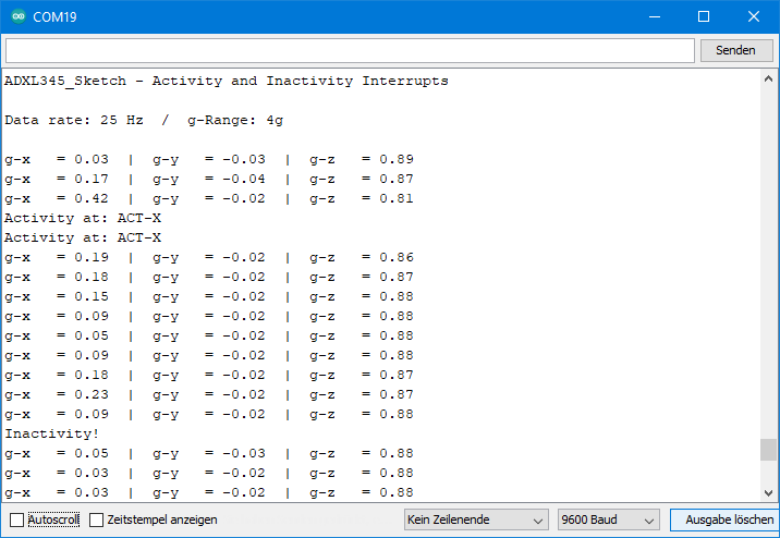
Output of the Activity / Inactivity Sketch
If the criterion for an activity interrupt is met, it is triggered. Since I have set the limits for activity and inactivity equal, an activity interrupt sets the timer for the inactivity interrupt back to zero.
The Link Bit
And now uncomment line 63 (setLinkBit(true)) and restart the sketch. Activity and Inactivity are now coupled. An Activity Interrupt – one at a time – can only be triggered if an Inactivity interrupt has been triggered before. Try it best.
Example sketch 9: ADXL345_auto_sleep.ino
Here we now catch up with auto sleep mode. When enabled, the ADXL345 goes into sleep mode when an Inactivity interrupt has been triggered. An Activity interrupt, on the other hand, wakes up the ADXL345. As in normal sleep mode, the ADXL345 periodically wakes up briefly at a selectable frequency of 1 to 8 Hz even without an Activity interrupt.
For Auto Sleep mode, the link bit must be set. This is done automatically by the library in the background. Accordingly, Activity and Inactivity interrupt are interdependent.
The following features are new:
setAutoSleep(true/false, frequency)- true/false is the on/off switch.
- frequency sets the wake-up frequency.
setAutoSleep(true/false)- Turn the Auto Sleep function on/off without changing the wake-up frequency.
#include<Wire.h>
#include<ADXL345_WE.h>
#define ADXL345_I2CADDR 0x53 // 0x1D if SDO = HIGH
const int int2Pin = 2;
volatile bool in_activity = false;

/* There are several ways to create your ADXL345 object:
 * ADXL345_WE myAcc = ADXL345_WE()                -> uses Wire / I2C Address = 0x53
 * ADXL345_WE myAcc = ADXL345_WE(ADXL345_I2CADDR) -> uses Wire / ADXL345_I2CADDR
 * ADXL345_WE myAcc = ADXL345_WE(&wire2)          -> uses the TwoWire object wire2 / ADXL345_I2CADDR
 * ADXL345_WE myAcc = ADXL345_WE(&wire2, ADXL345_I2CADDR) -> all together
 */
ADXL345_WE myAcc = ADXL345_WE(ADXL345_I2CADDR);

void setup() {
  Wire.begin();
  Serial.begin(115200);
  pinMode(int2Pin, INPUT);
  Serial.println("ADXL345_Sketch - Auto Sleep");
  Serial.println();
  if (!myAcc.init()) {
    Serial.println("ADXL345 not connected!");
  }
/* Insert your data from ADXL345_calibration.ino and uncomment for more precise results */
  // myAcc.setCorrFactors(-266.0, 285.0, -268.0, 278.0, -291.0, 214.0);

/* Choose the data rate         Hz
    ADXL345_DATA_RATE_3200    3200
    ADXL345_DATA_RATE_1600    1600
    ADXL345_DATA_RATE_800      800
    ADXL345_DATA_RATE_400      400
    ADXL345_DATA_RATE_200      200
    ADXL345_DATA_RATE_100      100
    ADXL345_DATA_RATE_50        50
    ADXL345_DATA_RATE_25        25
    ADXL345_DATA_RATE_12_5      12.5
    ADXL345_DATA_RATE_6_25       6.25
    ADXL345_DATA_RATE_3_13       3.13
    ADXL345_DATA_RATE_1_56       1.56
    ADXL345_DATA_RATE_0_78       0.78
    ADXL345_DATA_RATE_0_39       0.39
    ADXL345_DATA_RATE_0_20       0.20
    ADXL345_DATA_RATE_0_10       0.10
*/
  myAcc.setDataRate(ADXL345_DATA_RATE_25);
  Serial.print("Data rate: ");
  Serial.print(myAcc.getDataRateAsString());

/* Choose the measurement range
    ADXL345_RANGE_16G    16g
    ADXL345_RANGE_8G      8g
    ADXL345_RANGE_4G      4g
    ADXL345_RANGE_2G      2g
*/
  myAcc.setRange(ADXL345_RANGE_4G);
  Serial.print("  /  g-Range: ");
  Serial.println(myAcc.getRangeAsString());
  Serial.println();

  attachInterrupt(digitalPinToInterrupt(int2Pin), in_activityISR, RISING);

/* The following settings are similar to the settings in ADXL345_activity_inactivity_interrupt.ino */

/* Three parameters have to be set for activity:
    1. DC / AC Mode:
        ADXL345_DC_MODE - Threshold is the defined one (parameter 3)
        ADXL345_AC_MODE - Threshold = starting acceleration + defined threshold
    2. Axes, that are considered:
        ADXL345_000  -  no axis (which makes no sense)
        ADXL345_00Z  -  z
        ADXL345_0Y0  -  y
        ADXL345_0YZ  -  y,z
        ADXL345_X00  -  x
        ADXL345_X0Z  -  x,z
        ADXL345_XY0  -  x,y
        ADXL345_XYZ  -  all axes
    3. Threshold in g
*/
  myAcc.setActivityParameters(ADXL345_DC_MODE, ADXL345_XY0, 0.8);

/* Four parameters have to be set for in activity:
    1. DC / AC Mode:
        see activity parameters
    2. Axes, that are considered:
        see activity parameters
    3. Threshold in g
    4. Inactivity period threshold in seconds (max 255)
*/
  myAcc.setInactivityParameters(ADXL345_DC_MODE, ADXL345_XY0, 0.8, 10);

/* You can choose the following interrupts:
     Variable name:             Triggered, if:
    ADXL345_OVERRUN      -   new data replaces unread data
    ADXL345_WATERMARK    -   the number of samples in FIFO equals the number defined in FIFO_CTL
    ADXL345_FREEFALL     -   acceleration values of all axes are below the threshold defined in THRESH_FF
    ADXL345_INACTIVITY   -   acc. value of all included axes are < THRESH_INACT for period > TIME_INACT
    ADXL345_ACTIVITY     -   acc. value of included axes are > THRESH_ACT
    ADXL345_DOUBLE_TAP   -   double tap detected on one incl. axis and various defined conditions are met
    ADXL345_SINGLE_TAP   -   single tap detected on one incl. axis and various defined conditions are met
    ADXL345_DATA_READY   -   new data available

    Assign the interrupts to INT1 (INT_PIN_1) or INT2 (INT_PIN_2). Data ready, watermark and overrun are
    always enabled. You can only change the assignment of these which is INT1 by default.

    You can delete interrupts with deleteInterrupt(type);
*/
  myAcc.setInterrupt(ADXL345_ACTIVITY, INT_PIN_2);
  myAcc.setInterrupt(ADXL345_INACTIVITY, INT_PIN_2);

/* Auto sleep is connected with activity and inactivity. The device goes in sleep when inactivity is
    detected. The link bit must be set, if you want to use auto sleep. The library sets the link bit
    automatically. When the ADXL345 goes into sleep mode it wakes up periodically (default is 8 Hz).

    Choose the wake up frequency:
    ADXL345_WUP_FQ_1  =  1 Hz
    ADXL345_WUP_FQ_2  =  2 Hz
    ADXL345_WUP_FQ_4  =  4 Hz
    ADXL345_WUP_FQ_8  =  8 Hz

*/
  myAcc.setAutoSleep(true, ADXL345_WUP_FQ_1);
  // alternative: myAcc.setAutoSleep(true/false) without changing the wake up frequency.
  myAcc.readAndClearInterrupts();

}

void loop() {
  if ((millis() % 300) == 1) {
    xyzFloat g;
    myAcc.getGValues(&g);
    Serial.print("g-x   = ");
    Serial.print(g.x);
    Serial.print("  |  g-y   = ");
    Serial.print(g.y);
    Serial.print("  |  g-z   = ");
    Serial.println(g.z);
  }

  if(in_activity == true) {
    byte intSource = myAcc.readAndClearInterrupts();
    if(myAcc.checkInterrupt(intSource, ADXL345_ACTIVITY)){
      Serial.println("Activity!");
      if(!myAcc.isAsleep()){        //check the asleep bit
        Serial.println("I am awake!");
      }
    }

    if(myAcc.checkInterrupt(intSource, ADXL345_INACTIVITY)){
      Serial.println("Inactivity!");
      if(myAcc.isAsleep()){
        Serial.println("I am sleeping...");
      }
    }

    myAcc.readAndClearInterrupts();
    in_activity = false;
  }
}

void in_activityISR() {
  in_activity = true;
}
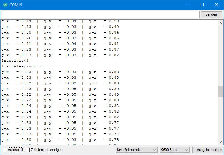
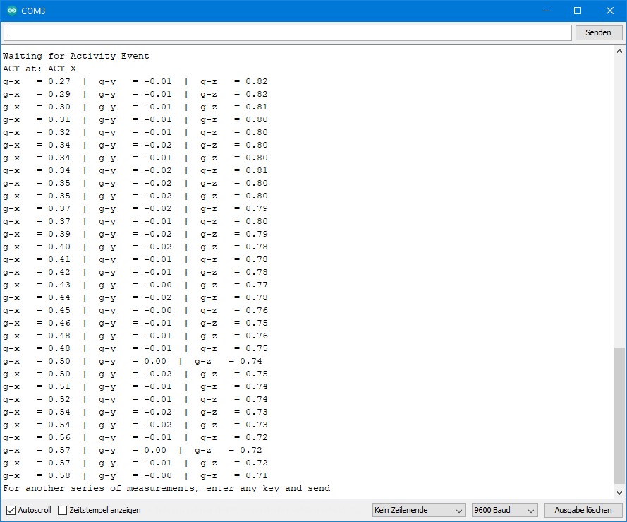
Output of the Auto Sleep sketch
Below you can see the excerpt of an output. I moved the ADXL345 below the activity limit. You can see that the ADXL345 is really asleep by the fact that the measured values are only updated once per second in sleep mode (as with the Sleep example sketch). Since the values are retrieved every 300 ms, 3-4 consecutive values are identical.
Single and Double Tap
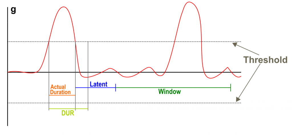
A single tap event is basically an activity event, but with a defined maximum duration (DUR). If the event is longer than DUR, it is not considered a single tap. For example, vibrations can be distinguished from a longer acceleration. The next tap can only be detected after a latency period (latent) has elapsed. The latency begins after the value has fallen below the threshold.
A Double Tap consists of two Single Taps with same parameters. The additional condition is that the second tap must take place in a time window that starts after the latency of the first tap has expired. Sounds complicated, but it’s not when you look at it graphically:
For single and double tap detection you need relatively high measuring frequencies. For example, it would make no sense to specify a value for DUR in the millisecond range, but record measured values in the seconds range. That has to fit together.
Example sketch 10: ADXL345_single_tap.ino
You can set various parameters for the Single and Double Tap. The parameters that apply to both the single and the double tap are defined by the following function:
setGeneralTapParameters(axes, g-threshold, duration, latent)- Axes are again the axes involved.
- g-threshold is the limit in g (this time without DC/AC mode).
- Vibrations usually cause high acceleration values and produce “echoes”, so the data sheet recommends 3 g as a starting value.
- duration is the maximum duration of the tap in milliseconds. The datasheet recommends values greater than 10 ms. The maximum is 159 ms.
- latent is the latency in milliseconds. It should be larger than 20 ms. The maximum is 318 ms.
You already know the function getActTapStatusAsString() from ADXL345_activity_inactivity.ino. Here it now returns the axis responsible for the tap interrupt or, if necessary, several.
#include<Wire.h>
#include<ADXL345_WE.h>
#define ADXL345_I2CADDR 0x53 // 0x1D if SDO = HIGH
const int int2Pin = 2;
volatile bool tap = false;

/* There are several ways to create your ADXL345 object:
 * ADXL345_WE myAcc = ADXL345_WE()                -> uses Wire / I2C Address = 0x53
 * ADXL345_WE myAcc = ADXL345_WE(ADXL345_I2CADDR) -> uses Wire / ADXL345_I2CADDR
 * ADXL345_WE myAcc = ADXL345_WE(&wire2)          -> uses the TwoWire object wire2 / ADXL345_I2CADDR
 * ADXL345_WE myAcc = ADXL345_WE(&wire2, ADXL345_I2CADDR) -> all together
 */
ADXL345_WE myAcc = ADXL345_WE(ADXL345_I2CADDR);

void setup() {
  Wire.begin();
  Serial.begin(115200);
  pinMode(int2Pin, INPUT);
  Serial.println("ADXL345_Sketch - Single Tap Interrupt");
  Serial.println();
  if (!myAcc.init()) {
    Serial.println("ADXL345 not connected!");
  }

/* Insert your data from ADXL345_calibration.ino and uncomment for more precise results */
  // myAcc.setCorrFactors(-266.0, 285.0, -268.0, 278.0, -291.0, 214.0);

/* Choose the data rate         Hz
    ADXL345_DATA_RATE_3200    3200
    ADXL345_DATA_RATE_1600    1600
    ADXL345_DATA_RATE_800      800
    ADXL345_DATA_RATE_400      400
    ADXL345_DATA_RATE_200      200
    ADXL345_DATA_RATE_100      100
    ADXL345_DATA_RATE_50        50
    ADXL345_DATA_RATE_25        25
    ADXL345_DATA_RATE_12_5      12.5
    ADXL345_DATA_RATE_6_25       6.25
    ADXL345_DATA_RATE_3_13       3.13
    ADXL345_DATA_RATE_1_56       1.56
    ADXL345_DATA_RATE_0_78       0.78
    ADXL345_DATA_RATE_0_39       0.39
    ADXL345_DATA_RATE_0_20       0.20
    ADXL345_DATA_RATE_0_10       0.10
*/
  myAcc.setDataRate(ADXL345_DATA_RATE_200);
  Serial.print("Data rate: ");
  Serial.print(myAcc.getDataRateAsString());

/* Choose the measurement range
    ADXL345_RANGE_16G    16g
    ADXL345_RANGE_8G      8g
    ADXL345_RANGE_4G      4g
    ADXL345_RANGE_2G      2g
*/
  myAcc.setRange(ADXL345_RANGE_8G);
  Serial.print("  /  g-Range: ");
  Serial.println(myAcc.getRangeAsString());
  Serial.println();

  attachInterrupt(digitalPinToInterrupt(int2Pin), tapISR, RISING);

/* The following four parameters have to be set for tap application (single and double):
    1. Axes, that are considered:
        ADXL345_000  -  no axis (which makes no sense)
        ADXL345_00Z  -  z
        ADXL345_0Y0  -  y
        ADXL345_0YZ  -  y,z
        ADXL345_X00  -  x
        ADXL345_X0Z  -  x,z
        ADXL345_XY0  -  x,y
        ADXL345_XYZ  -  all axes
    2. Threshold in g
        It is recommended to not choose the value to low. 3g is a good starting point.
    3. Duration in milliseconds (max 159 ms):
        maximum time that the acceleration must be over g threshold to be regarded as a single tap. If
        the acceleration drops below the g threshold before the duration is exceeded an interrupt will be
        triggered. If also double tap is active an interrupt will only be triggered after the double tap
        conditions have been checked. Duration should be greater than 10.
    4. Latency time in milliseconds (maximum: 318 ms): minimum time before the next tap can be detected.
        Starts at the end of duration or when the interrupt was triggered. Should be greater than 20 ms.
*/
  myAcc.setGeneralTapParameters(ADXL345_XY0, 3.0, 30, 100.0);

/* You can choose the following interrupts:
     Variable name:             Triggered, if:
    ADXL345_OVERRUN      -   new data replaces unread data
    ADXL345_WATERMARK    -   the number of samples in FIFO equals the number defined in FIFO_CTL
    ADXL345_FREEFALL     -   acceleration values of all axes are below the threshold defined in THRESH_FF
    ADXL345_INACTIVITY   -   acc. value of all included axes are < THRESH_INACT for period > TIME_INACT
    ADXL345_ACTIVITY     -   acc. value of included axes are > THRESH_ACT
    ADXL345_DOUBLE_TAP   -   double tap detected on one incl. axis and various defined conditions are met
    ADXL345_SINGLE_TAP   -   single tap detected on one incl. axis and various defined conditions are met
    ADXL345_DATA_READY   -   new data available

    Assign the interrupts to INT1 (INT_PIN_1) or INT2 (INT_PIN_2). Data ready, watermark and overrun are
    always enabled. You can only change the assignment of these which is INT1 by default.

    You can delete interrupts with deleteInterrupt(type);
*/
  myAcc.setInterrupt(ADXL345_SINGLE_TAP, INT_PIN_2);
  myAcc.readAndClearInterrupts();
}

/* In the main loop some checks are done:
    getActTapStatus() returns which axes are resposible activity interrupt as byte (code in library)
    getActTapStatusAsString() returns the axes that caused the interrupt as string
    readAndClearInterrupts(); return the interrupt type as byte (code in library)
    checkInterrupt(intSource, type) returns if intSource is type as bool
*/
void loop() {
  if ((millis() % 1000) == 1) {
    xyzFloat g;
    myAcc.getGValues(&g);
    Serial.print("g-x   = ");
    Serial.print(g.x);
    Serial.print("  |  g-y   = ");
    Serial.print(g.y);
    Serial.print("  |  g-z   = ");
    Serial.println(g.z);
  }

  if(tap == true) {
      //byte actTapSource = myAcc.getActTapStatus();
      //Serial.println(actTapSource, BIN);
      String axes = myAcc.getActTapStatusAsString();
      byte intSource = myAcc.readAndClearInterrupts();
      if(myAcc.checkInterrupt(intSource, ADXL345_SINGLE_TAP)){
        Serial.print("TAP at: ");
        Serial.println(axes);
      }

    delay(1000);
    myAcc.readAndClearInterrupts();
    tap = false;
  }
}

void tapISR() {
  tap = true;
}
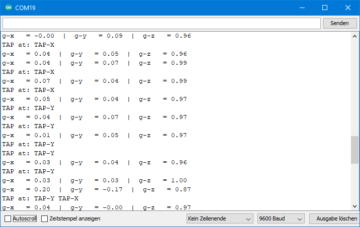
Output of the Single Tap sketch
For the output below, I first tapped the module several times in the direction of the x-axis and then in the direction of the y-axis. By the way, the measurement output has no deeper meaning. That’s just so it doesn’t get boring in between.
Example sketch 11: ADXL345_double_tap.ino
For Double Tap detection, you first define the general parameters as for the Singles Taps. Then you set two more parameters for the Double Taps:
setAdditionalDoubleTapParameters(suppress, window)- suppress is true or false and determines whether the suppress bit is set. If the suppress bit is set, then a second tap within the latency of the first tap invalidates the Double Tap condition. All right? If not, then go to the data sheet. There is a graphic on page 29 that should make things clearer.
- window sets the time window in which the second tap must take place in order to be counted as a double tap. The maximum is 318 ms.
In the example sketch I activated both the Single and the Double Tap Interrupt. Since there can be two different interrupts, it is necessary to check which interrupt was triggered.
The purpose of single and double tap detection is to look for characteristic shocks or vibrations. However, this requires a lot of trying out. Just play with the parameters.
Output of the Double Tap sketch
This is what an output might look like:

In this example, I tapped the ADXL345 twice in quick succession in the direction of the x-axis.
FIFO Functions
The FIFO buffer is a kind of recording device for measured values. This allows you to track very fast events at a measurement frequency of 3200 Hz, for example. Or you can analyze what happens before, around or after a particular event (activity or tap).
The FIFO has space for up to 32 measured values, namely full x,y,z data sets. You can select the number. FIFO stands for “first in, first out”, i.e. the measured values that are stored first are read first. Reading of the FIFO works like normal reading of measured values. However, the data registers are not supplied with fresh readings, but from the FIFO.
There are four modes of operation:
- Bypass:FIFO is disabled, which is the default. The measured values are written to the data registers, and new measured values overwrite the old ones.
- FIFO: you give the go-ahead to record the values. When the buffer contains the number of measured values you have defined, recording ends. The ADXL345 triggers the Watermark interrupt. It is a bit confusing that one of the FIFO modes is also called FIFO.
- Stream: as the name suggests, values are permanently written to the buffer. When the FIFO is full, values continue to be pushed in, and the oldest ones are pushed out. You define the end of the measured value recording.
- Trigger: Measurements are permanently recorded as in Stream mode. If you choose an event (= trigger, interrupt), only the number of values you have defined remains in the FIFO. Then, however, the FIFO is filled up with new readings up to 32. Then the process ends. So, you can set the middle of a measured value recording in the Trigger mode.
Example sketch 12: ADXL345_fifo_fifo.ino
The following new functions are used:
setFifoParameters(TriggerIntPin, number)- The TriggerIntPin only comes into play for the trigger mode. In this example, it doesn’t matter which parameter you choose.
- number sets the maximum number of measured values in the FIFO.
setFifoModes(mode)- With mode, you set – guess what – the FIFO mode.
The setting of FIFO mode is therefore simple. The other settings to make sure the whole thing works are a bit more complex. In particular, interrupts offer many possibilities for errors. It is important to follow the correct sequence.
A few notes for example:
- I set the measuring frequency at 6.25 Hz quite low. With 32 measured values it takes about 5 seconds until the FIFO is full. Enough time to tilt the ADXL345 slowly, for example.
- I deactivated all measurements until the beginning of the FIFO recording.
- The measurements are started with a countdown. Of course, you can also take something other than such a starting shot, for example an interrupt.
- The Watermark interrupt is assigned to INT2. It signals the end of the measurement.
- At the end of the measurement, I output 34 x,y,z value triples. This is more than the FIFO buffer contains. I just want to show that nothing happens after the 32nd value triplet.
#include<Wire.h>
#include<ADXL345_WE.h>
#define ADXL345_I2CADDR 0x53 // 0x1D if SDO = HIGH
const int int2Pin = 2;
volatile bool event = false;

/* There are several ways to create your ADXL345 object:
 * ADXL345_WE myAcc = ADXL345_WE()                -> uses Wire / I2C Address = 0x53
 * ADXL345_WE myAcc = ADXL345_WE(ADXL345_I2CADDR) -> uses Wire / ADXL345_I2CADDR
 * ADXL345_WE myAcc = ADXL345_WE(&wire2)          -> uses the TwoWire object wire2 / ADXL345_I2CADDR
 * ADXL345_WE myAcc = ADXL345_WE(&wire2, ADXL345_I2CADDR) -> all together
 */
ADXL345_WE myAcc = ADXL345_WE(ADXL345_I2CADDR);

void setup() {
  Wire.begin();
  Serial.begin(115200);
  pinMode(int2Pin, INPUT);
  Serial.println("ADXL345_Sketch - FIFO - Fifo Mode");
  Serial.println();
  if (!myAcc.init()) {
    Serial.println("ADXL345 not connected!");
  }

/* Insert your data from ADXL345_calibration.ino and uncomment for more precise results */
  // myAcc.setCorrFactors(-266.0, 285.0, -268.0, 278.0, -291.0, 214.0);

/* Choose the data rate         Hz
    ADXL345_DATA_RATE_3200    3200
    ADXL345_DATA_RATE_1600    1600
    ADXL345_DATA_RATE_800      800
    ADXL345_DATA_RATE_400      400
    ADXL345_DATA_RATE_200      200
    ADXL345_DATA_RATE_100      100
    ADXL345_DATA_RATE_50        50
    ADXL345_DATA_RATE_25        25
    ADXL345_DATA_RATE_12_5      12.5
    ADXL345_DATA_RATE_6_25       6.25
    ADXL345_DATA_RATE_3_13       3.13
    ADXL345_DATA_RATE_1_56       1.56
    ADXL345_DATA_RATE_0_78       0.78
    ADXL345_DATA_RATE_0_39       0.39
    ADXL345_DATA_RATE_0_20       0.20
    ADXL345_DATA_RATE_0_10       0.10
*/
  myAcc.setDataRate(ADXL345_DATA_RATE_3_13);
  Serial.print("Data rate: ");
  Serial.print(myAcc.getDataRateAsString());

/* Choose the measurement range
    ADXL345_RANGE_16G    16g
    ADXL345_RANGE_8G      8g
    ADXL345_RANGE_4G      4g
    ADXL345_RANGE_2G      2g
*/
  myAcc.setRange(ADXL345_RANGE_4G);
  Serial.print("  /  g-Range: ");
  Serial.println(myAcc.getRangeAsString());
  Serial.println();

/* Stop the measure mode - no new data will be obtained */
  myAcc.setMeasureMode(false);
  attachInterrupt(digitalPinToInterrupt(int2Pin), eventISR, RISING);

/* You can choose the following interrupts:
     Variable name:             Triggered, if:
    ADXL345_OVERRUN      -   new data replaces unread data
    ADXL345_WATERMARK    -   the number of samples in FIFO equals the number defined in FIFO_CTL
    ADXL345_FREEFALL     -   acceleration values of all axes are below the threshold defined in THRESH_FF
    ADXL345_INACTIVITY   -   acc. value of all included axes are < THRESH_INACT for period > TIME_INACT
    ADXL345_ACTIVITY     -   acc. value of included axes are > THRESH_ACT
    ADXL345_DOUBLE_TAP   -   double tap detected on one incl. axis and various defined conditions are met
    ADXL345_SINGLE_TAP   -   single tap detected on one incl. axis and various defined conditions are met
    ADXL345_DATA_READY   -   new data available

    Assign the interrupts to INT1 (INT_PIN_1) or INT2 (INT_PIN_2). Data ready, watermark and overrun are
    always enabled. You can only change the assignment of these which is INT1 by default.

    You can delete interrupts with deleteInterrupt(type);
*/
  myAcc.setInterrupt(ADXL345_WATERMARK, INT_PIN_2); // Interrupt when FIFO is full

/* The following two FIFO parameters need to be set:
    1. Trigger Bit: not relevant for this FIFO mode.
    2. FIFO samples (max 32). Defines the size of the FIFO. One sample is an x,y,z triple.
*/
  myAcc.setFifoParameters(ADXL345_TRIGGER_INT_1, 32);

/* You can choose the following FIFO modes:
    ADXL345_FIFO     -  you choose the start, ends when FIFO is full (at defined limit)
    ADXL345_STREAM   -  FIFO always filled with new data, old data replaced if FIFO is full; you choose the stop
    ADXL345_TRIGGER  -  FIFO always filled up to 32 samples; when the trigger event occurs only defined number of samples
                        is kept in the FIFO and further samples are taken after the event until FIFO is full again.
    ADXL345_BYPASS   -  no FIFO
*/
  myAcc.setFifoMode(ADXL345_FIFO);
  myAcc.readAndClearInterrupts();
}

void loop() {
  event = false;

  countDown(); // as an alternative you could define any other event to start to fill the FIFO
  myAcc.readAndClearInterrupts();
  myAcc.setMeasureMode(true); // this is the actual start
  while(!event){}  // event = true means WATERMARK interrupt triggered -> means FIFO is full
  myAcc.setMeasureMode(false);
  Serial.println("FiFo full");

  for(int i=0; i<34; i++){ // this is > 32 samples, but I want to show that the values do not change when FIFO is full
    xyzFloat g;
    myAcc.getGValues(&g);

    Serial.print("g-x   = ");
    Serial.print(g.x);
    Serial.print("  |  g-y   = ");
    Serial.print(g.y);
    Serial.print("  |  g-z   = ");
    Serial.println(g.z);
  }
  Serial.println("For another series of measurements, enter any key and send");

  while(!(Serial.available())){}
  Serial.read();
  Serial.println();
}

void eventISR() {
  event = true;
}

void countDown(){
  Serial.println("Move your ADXL345 to obtain interesting data");
  Serial.println();
  delay(1000);
  Serial.print("Fifo collection begins in 3, ");
  delay(1000);
  Serial.print("2, ");
  delay(1000);
  Serial.print("1, ");
  delay(1000);
  Serial.println("Now!");
}
Output of the FIFO FIFO Sketch
For the output shown below, I slowly rotated the ADXL345 around the y-axis (i.e. the x and z values vary).

Example sketch 13: ADXL345_fifo_stream.ino
The example sketch does not use any new functions. A few comments:
setFifoMode(ADXL345_STREAM)sets the stream mode.- As the event that ends the measurement recording, I have selected an Activity interrupt: 0.6 g on the x- or y-axis.
- The 32 measured values before the event occurs are stored in the FIFO.
#include<Wire.h>
#include<ADXL345_WE.h>
#define ADXL345_I2CADDR 0x53  // 0x1D if SDO = HIGH
const int int2Pin = 2;
volatile bool event = false;

/* There are several ways to create your ADXL345 object:
 * ADXL345_WE myAcc = ADXL345_WE()                -> uses Wire / I2C Address = 0x53
 * ADXL345_WE myAcc = ADXL345_WE(ADXL345_I2CADDR) -> uses Wire / ADXL345_I2CADDR
 * ADXL345_WE myAcc = ADXL345_WE(&wire2)          -> uses the TwoWire object wire2 / ADXL345_I2CADDR
 * ADXL345_WE myAcc = ADXL345_WE(&wire2, ADXL345_I2CADDR) -> all together
 */
ADXL345_WE myAcc = ADXL345_WE(ADXL345_I2CADDR);

void setup() {
  Wire.begin();
  Serial.begin(115200);
  pinMode(int2Pin, INPUT);
  Serial.println("ADXL345_Sketch - FIFO - Stream Mode");
  Serial.println();
  if (!myAcc.init()) {
    Serial.println("ADXL345 not connected!");
  }

/* Insert your data from ADXL345_calibration.ino and uncomment for more precise results */
  // myAcc.setCorrFactors(-266.0, 285.0, -268.0, 278.0, -291.0, 214.0);

/* Choose the data rate         Hz
    ADXL345_DATA_RATE_3200    3200
    ADXL345_DATA_RATE_1600    1600
    ADXL345_DATA_RATE_800      800
    ADXL345_DATA_RATE_400      400
    ADXL345_DATA_RATE_200      200
    ADXL345_DATA_RATE_100      100
    ADXL345_DATA_RATE_50        50
    ADXL345_DATA_RATE_25        25
    ADXL345_DATA_RATE_12_5      12.5
    ADXL345_DATA_RATE_6_25       6.25
    ADXL345_DATA_RATE_3_13       3.13
    ADXL345_DATA_RATE_1_56       1.56
    ADXL345_DATA_RATE_0_78       0.78
    ADXL345_DATA_RATE_0_39       0.39
    ADXL345_DATA_RATE_0_20       0.20
    ADXL345_DATA_RATE_0_10       0.10
*/
  myAcc.setDataRate(ADXL345_DATA_RATE_12_5);
  Serial.print("Data rate: ");
  Serial.print(myAcc.getDataRateAsString());

/* Choose the measurement range
    ADXL345_RANGE_16G    16g
    ADXL345_RANGE_8G      8g
    ADXL345_RANGE_4G      4g
    ADXL345_RANGE_2G      2g
*/
  myAcc.setRange(ADXL345_RANGE_4G);
  Serial.print("  /  g-Range: ");
  Serial.println(myAcc.getRangeAsString());
  Serial.println();

  attachInterrupt(digitalPinToInterrupt(int2Pin), eventISR, RISING);

 /* Three parameters have to be set for activity:
    1. DC / AC Mode:
        ADXL345_DC_MODE - Threshold is the defined one (parameter 3)
        ADXL345_AC_MODE - Threshold = starting acceleration + defined threshold
    2. Axes, that are considered:
        ADXL345_000  -  no axis (which makes no sense)
        ADXL345_00Z  -  z
        ADXL345_0Y0  -  y
        ADXL345_0YZ  -  y,z
        ADXL345_X00  -  x
        ADXL345_X0Z  -  x,z
        ADXL345_XY0  -  x,y
        ADXL345_XYZ  -  all axes
    3. Threshold in g
*/
  myAcc.setActivityParameters(ADXL345_DC_MODE, ADXL345_XY0, 0.6);

/* You can choose the following interrupts:
     Variable name:             Triggered, if:
    ADXL345_OVERRUN      -   new data replaces unread data
    ADXL345_WATERMARK    -   the number of samples in FIFO equals the number defined in FIFO_CTL
    ADXL345_FREEFALL     -   acceleration values of all axes are below the threshold defined in THRESH_FF
    ADXL345_INACTIVITY   -   acc. value of all included axes are < THRESH_INACT for period > TIME_INACT
    ADXL345_ACTIVITY     -   acc. value of included axes are > THRESH_ACT
    ADXL345_DOUBLE_TAP   -   double tap detected on one incl. axis and various defined conditions are met
    ADXL345_SINGLE_TAP   -   single tap detected on one incl. axis and various defined conditions are met
    ADXL345_DATA_READY   -   new data available

    Assign the interrupts to INT1 (INT_PIN_1) or INT2 (INT_PIN_2). Data ready, watermark and overrun are
    always enabled. You can only change the assignment of these which is INT1 by default.

    You can delete interrupts with deleteInterrupt(type);
*/
  myAcc.setInterrupt(ADXL345_ACTIVITY, INT_PIN_2);

/* The following two FIFO parameters need to be set:
    1. Trigger Bit: not relevant for this FIFO mode.
    2. FIFO samples (max 32). Defines the size of the FIFO. One sample is an x,y,z triple.
*/
  myAcc.setFifoParameters(ADXL345_TRIGGER_INT_1, 32);

 /* You can choose the following FIFO modes:
    ADXL345_FIFO     -  you choose the start, ends when FIFO is full (at defined limit)
    ADXL345_STREAM   -  FIFO always filled with new data, old data replaced if FIFO is full; you choose the stop
    ADXL345_TRIGGER  -  FIFO always filled up to 32 samples; when the trigger event occurs only defined number of samples
                        is kept in the FIFO and further samples are taken after the event until FIFO is full again.
    ADXL345_BYPASS   -  no FIFO
*/
  myAcc.setFifoMode(ADXL345_STREAM);

  myAcc.readAndClearInterrupts();

  Serial.println("Waiting for Activity Event - I propose to slowly turn the ADXL345");
}

/* In the main loop some checks are done:
    getActTapStatus() returns which axes are responsible for activity interrupt as byte (code in library)
    getActTapStatusAsString() returns the axes that caused the interrupt as string
    readAndClearInterrupts(); returns the interrupt type as byte (code in library)
    checkInterrupt(intSource, type) returns if intSource is type as bool
*/

void loop() {
  if(event){
    myAcc.setMeasureMode(false);
    //byte actTapSource = myAcc.getActTapStatus();
    //Serial.println(actTapSource, BIN);
    String axes = myAcc.getActTapStatusAsString();
    byte intSource = myAcc.readAndClearInterrupts();
    if(myAcc.checkInterrupt(intSource, ADXL345_ACTIVITY)){
        Serial.print("ACT at: ");
        Serial.println(axes);
    }
    printFifo();
    Serial.println("For another series of measurements, enter any key and send");
    while(!(Serial.available())){}
    Serial.read();
    Serial.println();
    Serial.println("Waiting for Activity Event");

    event = false;
    myAcc.readAndClearInterrupts();
    myAcc.setMeasureMode(true);
  }
}

void eventISR() {
  event = true;
}

void printFifo(){
  for(int i=0; i<32; i++){
    xyzFloat g;
    myAcc.getGValues(&g);

    Serial.print("g-x   = ");
    Serial.print(g.x);
    Serial.print("  |  g-y   = ");
    Serial.print(g.y);
    Serial.print("  |  g-z   = ");
    Serial.println(g.z);
  }
}
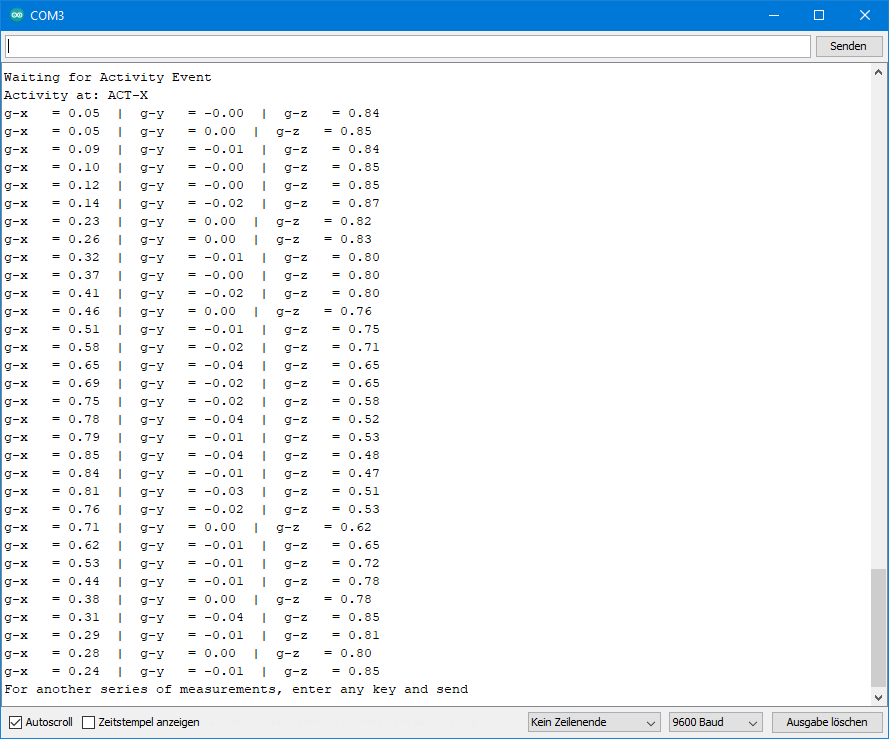
Output of THE FIFO Stream Sketch
Again, I slowly turned the ADXL345 around the y-axis.
Example sketch 14: ADXL345_fifo_trigger.ino
And now to the last example sketch. Here, the recording of FIFO data is controlled by a trigger. For this, I come back to the following function:
setFifoParameters(TriggerIntPin, number)- TriggerIntPin is set to INT1 or INT2. An interrupt on the selected pin is the trigger for the FIFO recording. You have to select an interrupt that you assign to this pin. Again, I have selected the Activity interrupt.
- number should be somewhere between 1 and 32. If you choose 32, that would be similar to Stream mode. If you choose 1, you might as well choose the fifo FIFO mode. For the example, I chose 15.
The question arises as to how to detect the completion of the measurements. Basically, this would work with the Watermark interrupt. However, if we assign this to INT2, we may get confused with the Activity interrupt. And if we assign it to INT1, then there may be problems with the Data Ready interrupt, which, stupidly, cannot be turned off. A pragmatic solution would be a simple delay which length would have to be adapted to the measuring frequency. Fortunately, the number of values present in the FIFO can be queried. The getFifoStatus() function returns the content of the FIFO status register. Its bits 0 to 5 contain the number of values in the FIFO. If bit 5 is set, there are 25 = 32 measured values in the FIFO. This results in
FIFO is full when (getFifoStatus() & 32) == true.
#include<Wire.h>
#include<ADXL345_WE.h>
#define ADXL345_I2CADDR 0x53  // 0x1D if SDO = HIGH
const int int2Pin = 2;
volatile bool event = false;

/* There are several ways to create your ADXL345 object:
 * ADXL345_WE myAcc = ADXL345_WE()                -> uses Wire / I2C Address = 0x53
 * ADXL345_WE myAcc = ADXL345_WE(ADXL345_I2CADDR) -> uses Wire / ADXL345_I2CADDR
 * ADXL345_WE myAcc = ADXL345_WE(&wire2)          -> uses the TwoWire object wire2 / ADXL345_I2CADDR
 * ADXL345_WE myAcc = ADXL345_WE(&wire2, ADXL345_I2CADDR) -> all together
 */
ADXL345_WE myAcc = ADXL345_WE(ADXL345_I2CADDR);

void setup() {
  Wire.begin();
  Serial.begin(115200);
  pinMode(int2Pin, INPUT);
  Serial.println("ADXL345_Sketch - FIFO - Trigger Mode");
  Serial.println();
  if (!myAcc.init()) {
    Serial.println("ADXL345 not connected!");
  }

/* Insert your data from ADXL345_calibration.ino and uncomment for more precise results */
  // myAcc.setCorrFactors(-266.0, 285.0, -268.0, 278.0, -291.0, 214.0);

/* Choose the data rate         Hz
    ADXL345_DATA_RATE_3200    3200
    ADXL345_DATA_RATE_1600    1600
    ADXL345_DATA_RATE_800      800
    ADXL345_DATA_RATE_400      400
    ADXL345_DATA_RATE_200      200
    ADXL345_DATA_RATE_100      100
    ADXL345_DATA_RATE_50        50
    ADXL345_DATA_RATE_25        25
    ADXL345_DATA_RATE_12_5      12.5
    ADXL345_DATA_RATE_6_25       6.25
    ADXL345_DATA_RATE_3_13       3.13
    ADXL345_DATA_RATE_1_56       1.56
    ADXL345_DATA_RATE_0_78       0.78
    ADXL345_DATA_RATE_0_39       0.39
    ADXL345_DATA_RATE_0_20       0.20
    ADXL345_DATA_RATE_0_10       0.10
*/
  myAcc.setDataRate(ADXL345_DATA_RATE_12_5);
  Serial.print("Data rate: ");
  Serial.print(myAcc.getDataRateAsString());

 /* Choose the measurement range
    ADXL345_RANGE_16G    16g
    ADXL345_RANGE_8G      8g
    ADXL345_RANGE_4G      4g
    ADXL345_RANGE_2G      2g
*/
  myAcc.setRange(ADXL345_RANGE_4G);
  Serial.print("  /  g-Range: ");
  Serial.println(myAcc.getRangeAsString());
  Serial.println();

  attachInterrupt(digitalPinToInterrupt(int2Pin), eventISR, RISING);

/* Three parameters have to be set for activity:
    1. DC / AC Mode:
        ADXL345_DC_MODE - Threshold is the defined one (parameter 3)
        ADXL345_AC_MODE - Threshold = starting acceleration + defined threshold
    2. Axes, that are considered:
        ADXL345_000  -  no axis (which makes no sense)
        ADXL345_00Z  -  z
        ADXL345_0Y0  -  y
        ADXL345_0YZ  -  y,z
        ADXL345_X00  -  x
        ADXL345_X0Z  -  x,z
        ADXL345_XY0  -  x,y
        ADXL345_XYZ  -  all axes
    3. Threshold in g
*/
  myAcc.setActivityParameters(ADXL345_DC_MODE, ADXL345_XY0, 0.6);

/* You can choose the following interrupts:
     Variable name:             Triggered, if:
    ADXL345_OVERRUN      -   new data replaces unread data
    ADXL345_WATERMARK    -   the number of samples in FIFO equals the number defined in FIFO_CTL
    ADXL345_FREEFALL     -   acceleration values of all axes are below the threshold defined in THRESH_FF
    ADXL345_INACTIVITY   -   acc. value of all included axes are < THRESH_INACT for period > TIME_INACT
    ADXL345_ACTIVITY     -   acc. value of included axes are > THRESH_ACT
    ADXL345_DOUBLE_TAP   -   double tap detected on one incl. axis and various defined conditions are met
    ADXL345_SINGLE_TAP   -   single tap detected on one incl. axis and various defined conditions are met
    ADXL345_DATA_READY   -   new data available

    Assign the interrupts to INT1 (INT_PIN_1) or INT2 (INT_PIN_2). Data ready, watermark and overrun are
    always enabled. You can only change the assignment of these which is INT1 by default.

    You can delete interrupts with deleteInterrupt(type);
*/
  myAcc.setInterrupt(ADXL345_ACTIVITY, INT_PIN_2);

/* The following two FIFO parameters need to be set:
    1. Trigger Bit: the trigger is an interrupt at INT1 or INT2
        ADXL345_TRIGGER_INT_1 - Trigger is an interrupt at INT1
        ADXL345_TRIGGER_INT_2 - Trigger is an interrupt at INT2
    2. FIFO samples (max 32). Defines the size of the FIFO. One sample is an x,y,z triple.
*/
  myAcc.setFifoParameters(ADXL345_TRIGGER_INT_2, 15);

/* You can choose the following FIFO modes:
    ADXL345_FIFO     -  you choose the start, ends when FIFO is full (at defined limit)
    ADXL345_STREAM   -  FIFO always filled with new data, old data replaced if FIFO is full; you choose the stop
    ADXL345_TRIGGER  -  FIFO always filled up to 32 samples; when the trigger event occurs only defined number of samples
                        is kept in the FIFO and further samples are taken after the event until FIFO is full again.
    ADXL345_BYPASS   -  no FIFO
*/
  myAcc.setFifoMode(ADXL345_TRIGGER);

  myAcc.readAndClearInterrupts();

  Serial.println("Waiting for Activity Event");
}

/* In the main loop some checks are done:
    getActTapStatus() returns which axes are responsible for activity interrupt as byte (code in library)
    getActTapStatusAsString() returns the axes that caused the interrupt as string
    readAndClearInterrupts(); returns the interrupt type as byte (code in library)
    checkInterrupt(intSource, type) returns if intSource is type as bool
*/
void loop() {

  if(event){
    String axes = myAcc.getActTapStatusAsString();
    byte intSource = myAcc.readAndClearInterrupts();
    if(myAcc.checkInterrupt(intSource, ADXL345_ACTIVITY)){
        Serial.print("Activity at: ");
        Serial.println(axes);
    }
    while(!(myAcc.getFifoStatus() & 32)){}
    printFifo();

    Serial.println("For another series of measurements, enter any key and send");
    while(!(Serial.available())){}
    Serial.read();
    Serial.println();
    myAcc.readAndClearInterrupts();
    myAcc.resetTrigger();
    Serial.println("Waiting for Activity Event");
    event = false;
  }
}

void eventISR() {
  event = true;
}

void printFifo(){
  for(int i=0; i<32; i++){
    xyzFloat g;
    myAcc.getGValues(&g);

    Serial.print("g-x   = ");
    Serial.print(g.x);
    Serial.print("  |  g-y   = ");
    Serial.print(g.y);
    Serial.print("  |  g-z   = ");
    Serial.println(g.z);
  }
}
Output of THE FIFO Trigger Sketch
For the output below, I rotated the ADXL345 around the y-axis until the activity interrupt was triggered and then turned it back. You can see that the measured value responsible for the Activity interrupt is in the middle of the FIFO values.
At this measurement frequency, this is just a gimmick. It becomes interesting if you change to high measuring frequencies and analyze a tap event in more detail, for example.
Closing words
Creating the library and example sketches was a pretty tough job due to the versatility of this component. I hope it was worth it and some people use the library. Bugs are not only not excluded in such a project, but almost inevitable. If you discover something or if you miss features, please get in touch.
Thank you so much Wolfgang! I had a lot of trouble with the sparkfruit and adafruit libraries to get interrupts working, but your library is much better and with significantly more helpful documentation.
Thank you so much for your motivating comment!
Hi Wolfgang,
Wow! What a fantastic effort doing all of this – Thank you!
I have spent many hours looking at the Sparkfun and also Adafruit libraries for the 345, however yours is so much easier to understand as you have broken it down into lots of different steps and have given great instructions and examples. Awesome:-)
Could you please suggest some logic/ideas/tips that could be used so that the Activity is only checked every second, and over a 10 second period we need to ensure that 7 out of 10 checks showed as Active before confirming that is indeed Active?
It would be kind of like a reverse of the Inactivity Interrupt because that is able to be set over a period of time.
Suggestions welcomed please.
Cheers from all the way down here in New Zealand:-)
Hi Steve,
first of all, thank you for your kind feedback 😀.
Regarding the programming challenge you are facing: I would take the acitivity/inactivity example sketch as a basis an only enable the activity interrupt. You can check every second whether an interrupt has been triggered. For this I would introduce a variable lastCheck:
if (millis() - lastCheck > 1000){
  if(activity){
    ....
  }
  lastCheck = millis()
}
This should be easy. The more challenging part is to count the interrupts over the last 10 checks. For this, would introduce an array of 10 integers and a counter which starts at zero. If an interrupt has been triggered during the last second, the array element 0 is 1, otherwise it is 0 and you increment the counter by 1. Then you do the same again after the next second and so on until you reach element 9. In this case you set the counter back to 0. So the array will always contain the results of the last ten checks and the sum of the elements tells you the number of interrupts. I hope this helps!
Greetings from Germany to NZ! Happy to get a comment from so far away!
Wolfgang
Hello Wolfgang,
I have a project to connect the ADXL345 to a ST-Nucleo-Board. I read the DEVID from the Chip and measure all signals with a scope. All level and timing constraints are o.k. and I get the correct answer 0xE5 from the device. After that I read the DEVID once again in my program and the return value is now 0xCB (on the scope and also the value in the controller). I tested this with and without the multi-byte-bit, but this does not change anything. I looked to the way you implemented your library and I saw no significant difference. For example, you have a 5 us delay from the falling edge of /CS to the transfer-start. I tried the communication with different delays, but 5 ns should also be enough.
I have now no idea why this is not working – maybe you have 🙂
with regards
Stefan
Module: GY-291
Power supply: 5V (internal regulator to 3,3 V)
logic-levels : 0 V and 3,3 V
SCLK-Frequency: About 660 kHz
one important information is missing: The communication protocol is SPI …
Hi Stefan,
this sounds strange. The register itself is read-only, so the DEVID will always remain the same. I have just added a function to read the DEVID to my library (getDeviceID). It is version 3.03. I have tried it on the Nucleo-L432KC. I read the DEVID several times, and it is always 0xE5. You may want to send me your code to wolfgang.ewald@wolles-elektronikkiste.de ? Maybe I find something.
I have to say, I am not really experienced with the Nucleo boards. I bought my first one a few days ago. Trying to reassign SPI pins (see comments of Bernard below) – no success yet.
Regards, Wolfgang
Hi, I am trying to use some GY-291 Module with a Nucleo32 L432KC with SPI but I can’t obtain a connection.
I define the connection like this :
“`
#define CS_PIN PB_0 // Chip Select Pin NSS/Bleu
#define MOSI_PIN PA_7 //SDI/SDA/Rouge
#define MISO_PIN PA_6 //SDO/Vert
#define SCK_PIN PA_5 //SCL/Orange
bool spi = true; // flag indicating that SPI shall be used
/* There are three ways to create your ADXL345 object in SPI mode
* ADXL345_WE myAcc = ADXL345_WE(CS_PIN, spi) -> uses SPI, spi is just a flag, see SPI example
* ADXL345_WE myAcc = ADXL345_WE(&SPI, CS_PIN, spi) -> uses SPI / passes the SPI object, spi is just a flag, see SPI example
* ADXL345_WE myAcc = ADXL345_WE(&SPI, CS_PIN, spi, MOSI_PIN, MISO_PIN, SCK_PIN) -> like the latter, but also changes the SPI pins
*/
ADXL345_WE myAcc = ADXL345_WE(CS_PIN, spi, /*mosi*/ MOSI_PIN, /*miso*/ MISO_PIN, /*sck*/ SCK_PIN);
“`
Do you have any idea of what I could have missed ? (Everything is working with I2C)
Thank you
Hi,
when you say you use an GY-291 module, it is not a module like this:
https://github.com/wollewald/ADXL345_WE#if-spi-does-not-work
Right? Just wanted to double-check.
I can confirm it works this way on an ESP32. I have just tried.
I don’t have Nucleo32 and no experience with it. So it’s hard for me to say whether there is something specific to consider when using SPI on such a board. Since I2C is working, at least the ADXL345 module seems to be OK.
Ususally, I am willing to buy modules when people have issues with it, but this one is quite expensive.
Maybe there are pins that are not suitable to use for SPI on this Board? E.g. I found this:
https://os.mbed.com/questions/79508/Conflict-between-serial-port-and-spi-on-/
Does that possibly help?
Do you have another SPI device you could test? Or could you test your ADXL345 board connected to the standard SPI pins (in case there is a standard on this board)?
Not sure what else I could recommend.
Thank you for your quick reply.
I have checked and there is no resistor connected to SDO.
I think you provided me the answer with the second link because I use PA_5, PA_6 but I need to dive into the manual and understand if the issue they describe is affecting me.
I will try the other SPI interface of the board and lastly I think I have some arduino nano somewhere to test
Please keep me updated – and good luck!
– The link with PA_5 and PA_6 was not the solution.
– I try the other SPI interface but still not working.
– I found back my arduino nano. At first it did not seems to work.
In fact, I did not managed to make the following syntax work even using the arduino nano default values (11,12,13):
ADXL345_WE(int cs, bool spi, int mosi = 999, int miso = 999, int sck = 999, int sid = -1)
Only thing that worked was to not overload the pins number and let their default value of 999.
Looking at the code it seems that in the init function the spi begin function is called only if those pin number keep their value of 999 (except for ESP32).
Am I missing something ?
I also try the syntax with the SPIClass parameter but it stay stuck in the init function, on the first writeRegister call…
Using:
ADXL345_WE(int cs, bool spi, int mosi = 999, int miso = 999, int sck = 999, int sid = -1)
for an Arduino Nano does not make much sense because you can’t change the SPI pins.
But I think I know now why it is not working on your board.
This is part of the init function:
bool ADXL345_WE::init(){
    if(useSPI){
        if(mosiPin == 999){
            _spi->begin();
        }
#ifdef ESP32
        else{
            _spi->begin(sckPin, misoPin, mosiPin, csPin);
        }
#endif
Changing the pins currently only works with the ESP32 because of the “#ifdef ESP32”. This was the only MCU I had tried where you can change the SPI pins. Do you know the identifier for your board? Then I can add it. You can find this in the compiler messages. I can also find it out, but not before tomorrow.
If you could send me your compiler messages (to wolfgang.ewald@wolles-elektronikkiste.de) then I can read it from there. At least if you have activated in the settings that all compiler messages shall be shown.
I have tried replacing
by
It works insofar as the code is now read in when chosing stm32 boards like yours, but there is an error message:
“no matching function for call to ‘SPIClass::begin(int&, int&, int&, int&)”
Then I found that reassigning SPI pins on an stm32 board works differently:
https://www.stm32duino.com/viewtopic.php?t=118
Finally, I have ordered the board you have. It will arrive tomorrow and I will try myself. Can’t promise that I will complete it tomorrow. You never know which unforeseeable problems occur.
If you want to try yourself you could create an SPI object as described in the link and then pass SPI with the constructor.
Thank you for your investment !
I have made some progress so far.
I am still using the _spi.begin() without parameters but I pass down a SPISettings objets at the ADXL34E object creation.
It “seems” to work, i.e. the connection is established and I can set and read data rate and g-range but then data read is garbadge…
Thank you again for you efforts.
I will have a look on the link you provided tomorrow
Yes, pins need to be re-assigned by creating an SPI-object. However, I was not able so far to reassign the pins. I tried this:
I also tried some other pins – but unsuccessfully. Everything works fine with the default SPI pins (D10-D13).
How did you get it so far?
Since we are running out space here, please start a new comment or answer by e-mail (wolfgang.ewald@wolles-elektronikkiste.de).
Thanks a lot for the clear explained and nice library!
My goal is to do a FFT vibration analysis using an accelerometer, I have a few questions about what the best use of this library would be for that application.
First, would you recommend using the ADXL345 with its fifo buffers, or is it unsuitable for this application?
As for an fft a consistent sampling interval is important, I thought that the best approach/settings would be:
sample rate of 3200Hz, SPI communication with interrupt pin configured as watermark, fifomode: fifo. And then using a single core of the esp32 to read the complete fifo buffer after an interrupt, and the other core to do other tasks. For the optimal fifo buffer size: I measured that reading the 32 samples of the FIFO buffer takes 1080us, but as the sample period is 312us (3200hz), then there would be a delay between sample 32 and 33, so then the FFT is not accurate. For a FIFO buffer size of 6 the reading time is 270us. Also, I measured how many samples the esp32 receives every second in the 3200hz mode, but that was only 2580 for buffer size of 32, and only 1880 for buffer size of 6, so there seems to be still something that’s wrong with this approach.
Would you recommend using this approach, of using another method with for example the FIFO stream mode, and an interrupt for every new sample?
Hi Thijs,
first of all, I have no experience with FFT vibration analysis. But I understand you need steady sampling at a high rate. Storing the measured data in the FIFO is quick, but if you read 32 results from the FIFO this will take time. And while reading the FIFO you might miss some data. I think the FIFO mode STREAM is better, and you constantly read from the FIFO buffer. But this is all some kind of speculation, since I have never tried to control larger data streams. In my examples, I just filled the FIFO completely once with 32 values and then read it. I would recommend that you try to manage a slower data rate first and then, if successfull, try to increase the rate. I would love to try myself, but unfortunately, I currently do not have the capacity.
Regards, Wolfgang
Regards, Wolfgang
Thanks for the awesome library.
I’ll explain my setup 1st.
I need to configure the tap threshold. And then I am interested in sensing tap from 8 different adxl345 connected to esp32-s3.
No additional info is needed on tap event.
My hopefull approach is
1. Configure set GeneralTapParameters of all 8 adxl345 via i2c
2. Connect vcc, gnd and int2 to esp32-s3 (without connecting sda and scl) (vcc and gnd will be common but int2 will be connected to 8 different gpio pins of esp32-s3)
3. Detect where tap came from based on which gpio has interrupt event.
Is my approach right?
Hi, if you don’t connect SDA and SCL, you won’t be able to communicate to the ADXL345 modules. So, how should you initiate the modules and set up the top interrupts. You can’t do this separate because the modules forget their settings when diconneczed from power. But even if you solve this issue, you stimmt need to clean the interrupts on the ADXL345 otherwise you won’t be able to detect new interrupts. With other words: all ADXL345 modules need to be connected via I2C. Which leads to the next question how to address 8 modules when only have two I2C-addresses. For this you can use an I2C multiplexer:
https://wolles-elektronikkiste.de/en/tca9548a-i2c-multiplexer
Regards, Wolfgang
Hi Wolfgang, I’m really thankful for your very well documented post. The example sketch files are well explained and really easy to understand and configure.
I’m using Lolin D1 mini board with ADXL345 to generate activity interrupts to wake-up the D1 mini from DeepSleep. I’m getting the changing g-values on the serial monitor as I move the ADXL but it’s not firing any interrupt. The pin connections are: 3v3–Vcc; Gnd–Gnd; D1–SCL; D2–SDA; D3–INT2. I used ICACHE_RAM_ATTR to load ISR in RAM as it was showing an error: “ISR not in IRAM”, which solved later. What more changes would I need to make the whole setup work?
#include
#include
#define ADXL345_I2CADDR 0x53
const int int2Pin = 3; //to receive interrupt on D3 pin
volatile bool in_activity = false;
ADXL345_WE myAcc = ADXL345_WE(ADXL345_I2CADDR);
void ICACHE_RAM_ATTR in_activityISR()
{
in_activity = true;
}
void setup()
{
Serial.begin(115200);
Wire.begin(D2, D1);
pinMode(int2Pin, INPUT);
Serial.println(“ADXL345_Sketch – Activity and Inactivity Interrupts”);
Serial.println();
if (!myAcc.init())
{
Serial.println(“ADXL345 not connected!”);
}
myAcc.setActivityParameters(ADXL345_AC_MODE, ADXL345_XYZ, 0.5);
myAcc.setInterrupt(ADXL345_ACTIVITY, INT_PIN_2);
attachInterrupt(digitalPinToInterrupt(int2Pin), in_activityISR, RISING);
}
void loop()
{
if ((millis() % 1000) == 1) \
{
xyzFloat g = myAcc.getGValues();
Serial.print(“x = “);
Serial.print(g.x);
Serial.print(” | y = “);
Serial.print(g.y);
Serial.print(” | z = “);
Serial.println(g.z);
}
if(in_activity == true)
{
Serial.println(“ISR executed”);
delay(1000);
myAcc.readAndClearInterrupts();
in_activity = false;
}
}
Hi Rohitashva,
first of all, thanks for the feedback. D3 is not Pin 3. If you wanted to use D3 as interrupt pin, you would need to write:
const int int2Pin = D3; and not:
const int int2Pin = 3;
But D3 is not a good choice. It can cause problems when the board is reset.
Take for example D5. Then it works.
Thank you for your quick response. I tried it with D5 and even lowered the threshold to 0.2 but it’s still not triggering the interrupt 🙁
That is strange. I took your code and only changed the int2pin to D5. I only had to add the libraries in the include statement (they go lost in the comment field, because it’s interpreted as HTML). I took a WEMOS D1 Mini board, and I chose “LOLIN(WEMOS) D1 R1 & mini” in the Arduino IDE. It’s only the interrupt that is not working? The acceleration values on the serial monitor are displayed correctly? Maybe try a pull down resistor on the Int2 to D5 line. But it should work without. Can measure the voltage on this line with a multimeter – is it low without interrupt as it should be?
Maybe try to change the interrupt logic with myAcc.setInterruptPolarity(ADXL345_ACT_LOW);? Of course then you also have to change the attachInterrupt parameter from RISING to FALLING.
I am a bit clueless…
Yes, the acceleration values are displayed correctly. Its only the interrupt that is not working. Though strange enough, yesterday the interrupt worked and the ISR was triggered (for some angle/orientation) but now again its not working. I don’t know what’s going on, I tried the same code and even tried changing some threshold value and interrupt polarity as suggested but it doesn’t seem to work again.
Maybe another myAcc.readAndClearInterrupts(); at the end of the setup could help. Just a gut feel. And I would try to attach a pull-down resistor (10 kilohms) to the interrupt line. I am not very optimistic, but you could try that quickly. And as proposed before, you could try to change the interrupt logic. In that case, I would attach a pull-up resistor to the interrupt line.
Sorry for the late reply. I tried attaching a resistor as pull-down and pull-up both ways with myAcc.readAndClearInterrupts(); in the setup as suggested but it didn’t worked. Also tried changing the interrupt logic but no success so far. When connecting the D5 with GND/3v3, It does fires an interrupt but not when INT2/INT1 pin is connected to GND/3v3.
I wanted to ask you if you also tried this code with D1 mini and is it working? Thank you!
Strange, as I wrote before I took your code, only changed the int2pin to D5, added the libraries and it worked on a Wemos D1 mini board. I will think about potential causes. But I don’t have an idea right now.
I have tried again this evening to see if this triggers any new ideas. It’s still working fine on my side. I am very motivated to identify the issue. There are not so many parameters and therefor it should be possible to identy what’s different on your and my side. But since this goes into the details I suggest we change the communication to e-mail. I’ll contact you.
Sure, let’s do that. Thank you very much!
For all people who read this: The issue is solved. It was simply a hardware issue. With a new ADXL345 module, it worked!
Thank you for this library. You have simplified everything for a beginner like me. I got the ADXL345 today, and I have interfaced it with the ESP32 D1 mini.
Happy to say your code worked well. I have edited it to have a high sampling rate.
I selected an ODR of 3200Hz. Does it mean I will have 3200 samples per second?
I will be glad if you can throw more light or, most importantly, a code to show the number of samples per second.
/***************************************************************************
* Example sketch for the ADXL345_WE library
*
* This sketch shows how use SPI for the basic data sketch. Please apply the
* same steps in the other sketches if you want to use SPI.
*
* Further information can be found on:
* https://wolles-elektronikkiste.de/adxl345-teil-1 (German)
* https://wolles-elektronikkiste.de/en/adxl345-the-universal-accelerometer-part-1 (English)
*
***************************************************************************/
#include
#include
#define CS_PIN 5 // Chip Select Pin
bool spi = true; // flag that SPI shall be used
/* There are two ways to create your ADXL345 object in SPI mode:
* ADXL345_WE myAcc = ADXL345_WE(CS_PIN, spi) -> uses SPI, spi is just a flag, see SPI example
* ADXL345_WE myAcc = ADXL345_WE(&SPI, CS_PIN, spi) -> uses SPI / passes the SPI object, spi is just a flag, see SPI example
*/
ADXL345_WE myAcc = ADXL345_WE(CS_PIN, spi);
void setup(){
Serial.begin(2000000);
//Serial.println(“ADXL345_Sketch – Basic Data”);
if(!myAcc.init()){
Serial.println(“ADXL345 not connected!”);
}
/* You can set the SPI clock speed. Default is 8 MHz. */
myAcc.setSPIClockSpeed(4000000);
/* Choose the data rate Hz
ADXL345_DATA_RATE_3200 3200
ADXL345_DATA_RATE_1600 1600
ADXL345_DATA_RATE_800 800
ADXL345_DATA_RATE_400 400
ADXL345_DATA_RATE_200 200
ADXL345_DATA_RATE_100 100
ADXL345_DATA_RATE_50 50
ADXL345_DATA_RATE_25 25
ADXL345_DATA_RATE_12_5 12.5
ADXL345_DATA_RATE_6_25 6.25
ADXL345_DATA_RATE_3_13 3.13
ADXL345_DATA_RATE_1_56 1.56
ADXL345_DATA_RATE_0_78 0.78
ADXL345_DATA_RATE_0_39 0.39
ADXL345_DATA_RATE_0_20 0.20
ADXL345_DATA_RATE_0_10 0.10
*/
myAcc.setDataRate(ADXL345_DATA_RATE_3200);
// delay(100);
//Serial.print(“Data rate: “);
//Serial.print(myAcc.getDataRateAsString());
/* In full resolution the size of the raw values depend on the
range: 2g = 10 bit; 4g = 11 bit; 8g = 12 bit; 16g =13 bit;
uncomment to change to 10 bit for all ranges.
*/
// myAcc.setFullRes(false);
/* Choose the measurement range
ADXL345_RANGE_16G 16g
ADXL345_RANGE_8G 8g
ADXL345_RANGE_4G 4g
ADXL345_RANGE_2G 2g
*/
myAcc.setRange(ADXL345_RANGE_2G);
// Serial.print(” / g-Range: “);
//Serial.println(myAcc.getRangeAsString());
// Serial.println();
/* Uncomment to enable Low Power Mode. It saves power but slightly
increases noise. LowPower only affetcs Data Rates 12.5 Hz to 400 Hz.
*/
// myAcc.setLowPower(true);
}
/* The LSB of the Data registers is 3.9 mg (milli-g, not milligramm).
This value is used calculating g from raw. However, this is an ideal
value which you might want to calibrate.
*/
void loop() {
//xyzFloat raw = myAcc.getRawValues();
xyzFloat g = myAcc.getGValues();
/* Serial.print(“Raw-x = “);
Serial.print(raw.x);
Serial.print(” | Raw-y = “);
Serial.print(raw.y);
Serial.print(” | Raw-z = “);
Serial.println(raw.z);*/
//Serial.print(“g-x = “);
Serial.print((g.x)/0.10197);
Serial.print(“,”);
Serial.print(g.y/0.10197);
Serial.print(“,”);
Serial.println(g.z/0.10197);
//Serial.println();
// Wait for 1/3200 seconds (sampling period)
delayMicroseconds(313);
}
Hi, yes, 3200 is the data rate in samples per second. But with the sketch above you won’t be able to display 3200 measured values in a second. The bottleneck is the slow Serial.print() function. You can test this: forget the ADXL345 for a moment and just write a short sketch in which repeat e.g. Serial.println(“Hi ilook”) in for-loop let’s say 1000 times. Measure the time via millis() before and after. And in your sketch you are even using 12 Serial.print() commands for one measured value. And also the SPI communication takes time. Maybe it’s possible to store 3200 samples per second on the flash of the ESP32, but I haven’t tried. But again: displaying 3200 samples per second – not possible.
And finally, if you want to achieve a high data rate, then I would not apply a delay in loop(), but use the data ready interrupt.
Thanks for your responses and suggestion.
How do I use the data ready interrupt with the millis() to show the ? I really want to achieve high data rate. A code would be appreciated.
Serial.print((g.x)/0.10197); is this right? i did that because I wanted the values to be between +/- 9.8 m/s^2
Sorry, I have seen your code on data ready interrupt. Can I use this with SPI? I am using the sensor for vibration analysis.
You can use all features with both I2C and SPI. Some lines at the top of the sketch need to be modified. There is one SPI example sketch. If you compare it with the corresponding I2C sketch you will see what needs to be changed and you can apply the same to the data ready interrupt example.
Just determine the current time with millis() like this:
unsigned long startingTime = millis();
Then you read values let’s say 1000 times using a for construct:
for(int i=0; i<1000; i++){
Read values, print them, or whatever you want to do }
And then:
unsigned long timeNeeded = millis() – startingTime;
That’s basically all.
The other question: yes, if you want to turn g-values into m/s^2 then divide by 0.1097 or multiply by 9,81.
Super great job!
Just 2 questions…
According datasheet, use of the 3200 Hz and 1600 Hz output data rates is only recommended with SPI communication rates greater than or equal to 2 MHz (datasheet->page15) Did you take this into account?
I’m trying to guess which is the maximum number of readings that I can get with this module in one second…Could you shed some light on this?
Thank you!
Hi, first of all thanks for the feedback. You are right, you won’t be able to get the highest sample rates with I2C. Maybe I should mention this clearly. Not sure where the exact limit is. You can increase it by changing from 100 to 400 kHz using Wire.setClock(400000). I’ve implemented SPI, so you can change if you need. With SPI you should achieve the maximum as long as you don’t apply slow commands like Serial.print between the sample queries.
Wolfgang, do you mean you can increase the I2C clock speed from 100 to 400 kHz using Wire.setClock(400000)?
Of course! Well spottet – thanks! I have just changed it.
Wofgang,
I find your website to be a very useful resource, regardless of minor issues such as the one I pointed out. I hope you continue contributing to the knowledge and understanding of the international electronics community with your educational postings.
Chip
Arizona, USA
Thank you!
Do you have a simple sketch to wake a sleeping arduino with the adxl345. I have tried it a few different ways but keep coming up short.
Wonderful job on documenting and explaining your libraries! this has been incredibly helpful!!
Thanks for your kind feedback!
And to answer your question: you just need to set up an interrupt on the ADXL side (activity, inactivity, freefall, etc) and an interrupt on the Arduino side. Connect the interrupt pin of the ADXL345 with the interrupt pin of the Arduino. Don’t forget to pull it down (or up for active low setting). Interrupts are a source of many potential bugs! In this specific example it’s very important to clear the interrupt before the Arduino is sent to sleep.
Hope this helps. If you have questions regarding the code please ask!
#include <avr/sleep.h>#include<Wire.h>
#include<ADXL345_WE.h>
#define ADXL345_I2CADDR 0x53
const int int2Pin = 2;
ADXL345_WE myAcc = ADXL345_WE(ADXL345_I2CADDR);
void setup(){
Wire.begin();
Serial.begin(9600);
delay(100);
if (!myAcc.init()) {
Serial.println("ADXL345 not connected!");
}
pinMode(int2Pin, INPUT);
attachInterrupt(digitalPinToInterrupt(int2Pin), activityISR, RISING);
myAcc.setActivityParameters(ADXL345_DC_MODE, ADXL345_XY0, 0.5);
myAcc.setInterrupt(ADXL345_ACTIVITY, INT_PIN_2);
}
void loop(){
Serial.println("Going to sleep in 2 seconds...");
delay(2000);
myAcc.readAndClearInterrupts();
set_sleep_mode(SLEEP_MODE_PWR_DOWN);
sleep_mode();
// sleeping now and waiting for interrupt
Serial.println("I woke up!");
}
void activityISR(){
}
WOW! THANKS!
I was definitely over complicating it! haha!
This will be a wonderful place for me to start with.
If I have more questions I will reach out.
THANK YOU SO MUCH!!!
Hello,
How do I get the .h and .c files (library?):
#include
#include
Thank you,
Traian Morar
Dear Traian,
the easiest ways to get the library are:
1) If you use the Arduino IDE, go to the library manager. There you search for ADXL345_WE. Then click on install.
or:
2) Go to GitHub with this link:
https://github.com/wollewald/ADXL345_WE
There is a green button (“Code”). Click on it and choose download as ZIP. Extract the Zip file in your library folder.
If you still have problems, then google “install Arduino libraries ” or similar – There are lots of tutorials.
Good luck and have fun!
Best wishes, Wolfgang
Thank you for a well written article. The explanation off the interrupts was very good and made me switch from the 5060 to this module.
Which sample should I use to make the detection in one direction possible like the detection of braking and acceleration in combination with the interupts?
Thank you,
Peter
Hi Peter,
thanks for the feedback. Acceleration interrupts are covered in the example ADXL345_activity_inactivity_interrupt.ino. The key functions are setActivityParameters() and setInterrupt(). Activity interrupt is maybe not the ideal name, acceleration interrupt would be better, but I wanted to use the nomenclature of the data sheet. Have fun with your project!
Wolfgang
Thank you for explaining.
Peter
Hi Wolfgang, thank you so much for this post. Very informative and very clear. I have been trying to read the ADXL345 data sheet or should I say sheets for a long time now and I’ve looked at so many videos, instruction sites and forums that tell you exactly how easy it is but then do not quite show you how it’s done. Your style of instruction is very good and has helped me understand the ADXL345 a lot better. Thank you once again.
Thank you so much – this comment is very motivating for me!