About this post
I2C devices usually have a set of fixed addresses that can be set via address pins or jumpers. Some, such as the MCP23017 port expander, are quite lush with 8 addresses. Others, such as the BH1750FVI ambient light sensor, have only 2 addresses to choose from. But what if you can’t get by with it? A very convenient solution to this problem is the I2C multiplexer TCA9548A, which I will introduce in this article. In addition, I’ll show you how to do I2C multiplexing with a simple MOSFET.
The article is structured as follows:
- Technical features of the TCA9548A
- Connecting the TCA9548A to the microcontroller
- Control – Basics
- Using a single TCA9548A:
- one I2C device per channel
- multiple I2C devices with different addresses per channel
- Using multiple TCA9548A
- I2C multiplexing with MOSFETs
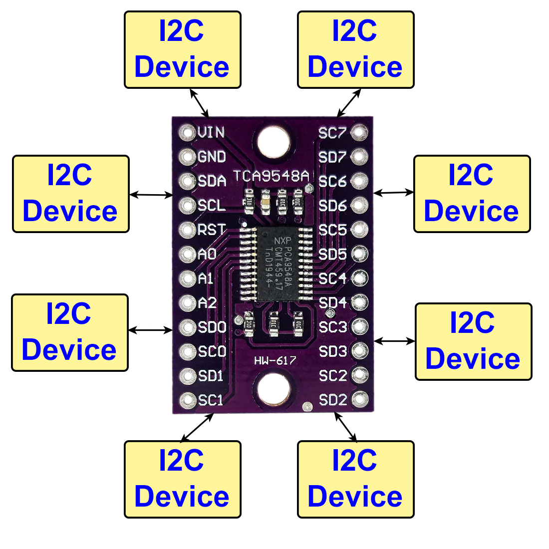
Technical features of the TCA9548A
With its eight channels, the TCA9548A makes it possible to operate eight I2C devices with the same address on one I2C bus. For the TCA9548A itself, you can set eight addresses according to the following scheme:
- 1 1 1 0 A2 A1 A0
- Ax = 0 if connected to LOW, Ax = 1 if connected to HIGH
- Therefore, you can set the following addresses: 1110000 to 1110111 or 0x70 to 0x77
This means with eight TCA9548As you could run 64 I2C devices that all have the same I2C address.

On the microcontroller side (connectors SDA / SCL) pull-up resistors are integrated, which pull the voltage to the VIN level. The eight channels do not have built-in pull-ups. What at first looks like a disadvantage is an advantage because it allows you to work with different bus voltages. For example, you could select 3.3 volts for VIN and thus also for the I2C lines to the microcontroller. Independently you can then pull up the individual channels to e.g. 5 volts with external pull-up resistors.
Here are further technical features at a glance:
- Power supply: 1.65 – 5.5 volts
- Maximum I2C bus frequency: 400 kHz
- Low-active reset pin
- All inputs 5V tolerant
- Multiple or all channels can be activated at the same time
For more details, see the technical data sheet.
You get the TCA9548A as a module for a few euros in online stores like Amazon or AliExpress.
Connecting the TCA9548A to the microcontroller
In the following figure you can see how to connect the TCA9548A using an Arduino UNO as an example. For a better overview, I have only shown a single I2C device.
The HIGH level of the Arduino UNO I2C lines is 5 volts. Accordingly, VIN should also be supplied with 5 volts. The address pins are unconnected in this example and therefore at GND level. The address is thus 0x70. On the I2C “slave” side, pull-ups are required if the connected component does not provide them.

Control – Basics
The TCA9548A has only one register with write access, namely the control register:

A “1” means that the channel is active, a “0” means that the channel is inactive. For example, if you write a 151 in the register, this corresponds to the binary number 10010111, i.e. channels 0,1,2,4 and 7 are active. To set specific bits of the register, it is best to use binary operations:
![\[ Control\; Register=151 = (1 << 7)|(1 << 4)|(1 << 2)|(1 << 1)|(1 << 0) \]](https://wolles-elektronikkiste.de/wp-content/ql-cache/quicklatex.com-d4d0e6e6065956135b85bae87c248c92_l3.png "Rendered by QuickLaTeX.com")
In the example sketches of this article, however, only one channel is active at a time. The following mini sketch opens channel 0 by setting the bit 0 of the control register:
#include<Wire.h>
#define TCA9548A_I2C_ADDRESS  0x70
#define TCA9548A_CHANNEL_0    0

void setup() {
  Wire.begin();
  setTCAChannel(TCA9548A_CHANNEL_0);
}

void loop() {
}

void setTCAChannel(byte i){
  Wire.beginTransmission(TCA9548A_I2C_ADDRESS);
  Wire.write(1 << i);
  Wire.endTransmission();
}
To get started, you can try the following: Take your favorite I2C device and re-build the circuit above. Then upload an I2C scanner sketch. You can find something like this e.g. here. The scanner should find the address 0x70. Then you upload the TCA9548A_set_channel sketch without disconnecting the TCA9548A from power in between. Then you upload the scanner sketch again. It should then display the 0x70 and address of your I2C part.
Basically, that is all you need! You only have to switch the channels on and off selectively to address the desired I2C device. And if you write a “0” in the control register, all channels are disabled. In practice, however, it can quickly become confusing, especially if an object is created for each I2C device.
Use of a single TCA9548A
A single TCA9548A with one I2C device per channel
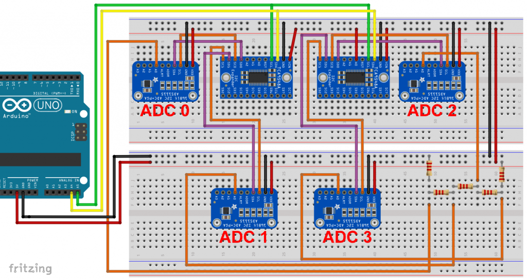
In the following examples I use the A/D converter ADS1115 as I2C device representative. You don’t have to deal with the details of the ADS1115 to understand this article. Just note that each ADS1115 needs to be initialized and requires a few settings (setVoltageRange_mV, setCompareChannels and setMeasureMode).
The wiring of the I2C lines is probably no surprise. The orange lines and the resistors are only used to measure a few different voltages at the A0 input of the ADS1115 modules. Since the address pins of the ADS1115 modules are not connected, the I2C address for all of them is 0x48.


In the corresponding sketch, an individual object is created for each ADS1115. This is followed by the initialization and setting of the parameters. In the main loop, the measured values of the ADS1115 modules are queried and output.
#include<ADS1115_WE.h>
#include<Wire.h>
#define AD1115_I2C_ADDRESS 0x48
#define TCA_I2C_ADDRESS    0x70

ADS1115_WE adc_0(AD1115_I2C_ADDRESS);
ADS1115_WE adc_1(AD1115_I2C_ADDRESS);
ADS1115_WE adc_2(AD1115_I2C_ADDRESS);
ADS1115_WE adc_3(AD1115_I2C_ADDRESS);

void setup() {
  Wire.begin();
  Serial.begin(9600);

  setTCAChannel(0);
  if(!adc_0.init()){
    Serial.print("ADS1115 No 0 not connected!");
  }
  adc_0.setVoltageRange_mV(ADS1115_RANGE_6144); // setting voltage range
  adc_0.setCompareChannels(ADS1115_COMP_0_GND); // setting adc channel
  adc_0.setMeasureMode(ADS1115_CONTINUOUS); // setting adc mode

  setTCAChannel(1);
  if(!adc_1.init()){
      Serial.print("ADS1115 No 1 not connected!");
  }
  adc_1.setVoltageRange_mV(ADS1115_RANGE_6144); // setting parameters
  adc_1.setCompareChannels(ADS1115_COMP_0_GND);
  adc_1.setMeasureMode(ADS1115_CONTINUOUS);

  setTCAChannel(2);
  if(!adc_2.init()){
      Serial.print("ADS1115 No 2 not connected!");
  }
  adc_2.setVoltageRange_mV(ADS1115_RANGE_6144); // setting parameters
  adc_2.setCompareChannels(ADS1115_COMP_0_GND);
  adc_2.setMeasureMode(ADS1115_CONTINUOUS);

  setTCAChannel(3);
  if(!adc_3.init()){
    Serial.print("ADS1115 No 3 not connected!");
  }
  adc_3.setVoltageRange_mV(ADS1115_RANGE_6144); // setting parameters
  adc_3.setCompareChannels(ADS1115_COMP_0_GND);
  adc_3.setMeasureMode(ADS1115_CONTINUOUS);
}

void loop() {
  float voltage = 0.0;

  setTCAChannel(0);
  voltage = adc_0.getResult_V();
  Serial.print("Voltage [V], ADS1115 No 0: ");
  Serial.println(voltage);

  setTCAChannel(1);
  voltage = adc_1.getResult_V();
  Serial.print("Voltage [V], ADS1115 No 1: ");
  Serial.println(voltage);

  setTCAChannel(2);
  voltage = adc_2.getResult_V();
  Serial.print("Voltage [V], ADS1115 No 2: ");
  Serial.println(voltage);

  setTCAChannel(3);
  voltage = adc_3.getResult_V();
  Serial.print("Voltage [V], ADS1115 No 3: ");
  Serial.println(voltage);

  Serial.println("****************************");
  delay(1000);
}

void setTCAChannel(byte i){
  Wire.beginTransmission(TCA_I2C_ADDRESS);
  Wire.write(1 << i);
  Wire.endTransmission();
}
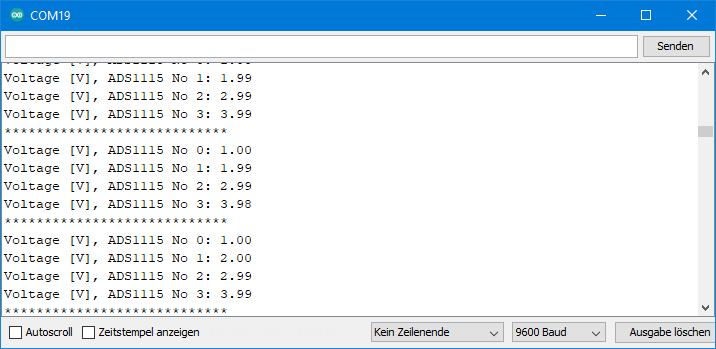
Output of the sketches
The output of this and all the following sketches is the same:
Some simplifications
With the last sketch I wanted to show the basic principles. But the code can be shortened significantly. In the following simplified version, I have defined the ADS1115 objects as an array and outsourced the repeatedly used code to functions.
#include<ADS1115_WE.h>
#include<Wire.h>
#define AD1115_I2C_ADDRESS 0x48
#define TCA_I2C_ADDRESS    0x70

ADS1115_WE adc[4];

void setup() {
  Wire.begin();
  Serial.begin(9600);

  for(int i=0; i<4; i++){
    adc[i] =  ADS1115_WE(AD1115_I2C_ADDRESS);
    setTCAChannel(i);
    setupAdc(i);
  }
}

void loop() {
  float voltage = 0.0;

  for(int i=0; i<4; i++){
    setTCAChannel(i);
    voltage = adc[i].getResult_V();
    Serial.print("Voltage [V], ADS1115 No ");
    Serial.print(i);
    Serial.print(": ");
    Serial.println(voltage);
  }
  Serial.println("****************************");
  delay(1000);
}

void setTCAChannel(byte i){
  Wire.beginTransmission(TCA_I2C_ADDRESS);
  Wire.write(1 << i);
  Wire.endTransmission();
}

void setupAdc(byte i){
  if(!adc[i].init()){
    Serial.print("ADS1115 No ");
    Serial.print(i);
    Serial.println(" not connected!");
  }
  adc[i].setVoltageRange_mV(ADS1115_RANGE_6144);
  adc[i].setCompareChannels(ADS1115_COMP_0_GND);
  adc[i].setMeasureMode(ADS1115_CONTINUOUS);
}
Further simplification: use of only one object
Perhaps some people noticed that all module settings are the same. It is therefore not necessary to create a separate object for each ADS1115 module. This offers the possibility to make the code even simpler. If the I2C devices require individual settings (calibration factors or similar), this simplification is not possible.
#include<ADS1115_WE.h>
#include<Wire.h>
#define AD1115_I2C_ADDRESS 0x48
#define TCA_I2C_ADDRESS    0x70

ADS1115_WE adc(AD1115_I2C_ADDRESS);

void setup() {
  Wire.begin();
  Serial.begin(9600);

  for(int i=0; i<4; i++){
    setTCAChannel(i);
    setupAdc(i);
  }
}

void loop() {
  float voltage = 0.0;

  for(int i=0; i<4; i++){
    setTCAChannel(i);
    voltage = adc.getResult_V();
    Serial.print("Voltage [V], ADS1115 No ");
    Serial.print(i);
    Serial.print(": ");
    Serial.println(voltage);
  }
  Serial.println("****************************");
  delay(1000);
}

void setTCAChannel(byte i){
  Wire.beginTransmission(TCA_I2C_ADDRESS);
  Wire.write(1 << i);
  Wire.endTransmission();
}

void setupAdc(byte i){
  if(!adc.init()){
    Serial.print("ADS1115 No ");
    Serial.print(i);
    Serial.println(" not connected!");
  }
  adc.setVoltageRange_mV(ADS1115_RANGE_6144);
  adc.setCompareChannels(ADS1115_COMP_0_GND);
  adc.setMeasureMode(ADS1115_CONTINUOUS);
}
One TCA9548A with multiple I2C devices per channel
If you want to control more than eight I2C devices and they allow the setting of the I2C address, you can use multiple I2C devices per channel. The ADS1115 allows four different addresses to be set. Therefore, you can easily operate 32 ADS1115 modules with a single TCA9548A. I show the principle with four ADS1115 modules on two channels. Here is the circuit:

Note that the address pins of ADCs No 1 and No 3 are connected to VCC. Their address changes to 0x49. Since the settings of the ADS1115 modules are identical except for the I2C address, there would be potential for further simplifications.
#include<ADS1115_WE.h>
#include<Wire.h>
#define AD1115_I2C_ADDRESS_A  0x48
#define AD1115_I2C_ADDRESS_B  0x49
#define TCA_I2C_ADDRESS       0x70

ADS1115_WE adc[4];

void setup() {
  Wire.begin();
  Serial.begin(9600);

  setTCAChannel(0);
  adc[0] =  ADS1115_WE(AD1115_I2C_ADDRESS_A);
  setupAdc(0);
  adc[1] =  ADS1115_WE(AD1115_I2C_ADDRESS_B);
  setupAdc(1);

  setTCAChannel(1);
  adc[2] =  ADS1115_WE(AD1115_I2C_ADDRESS_A);
  setupAdc(2);
  adc[3] =  ADS1115_WE(AD1115_I2C_ADDRESS_B);
  setupAdc(3);
}

void loop() {
  float voltage = 0.0;

  for(int i=0; i<4; i++){
    if(i<2){
      setTCAChannel(0);
    }
    else{
      setTCAChannel(1);
    }
    voltage = adc[i].getResult_V();
    Serial.print("Voltage [V], ADS1115 No ");
    Serial.print(i);
    Serial.print(": ");
    Serial.println(voltage);
  }
  Serial.println("****************************");
  delay(1000);
}

void setTCAChannel(byte i){
  Wire.beginTransmission(TCA_I2C_ADDRESS);
  Wire.write(1 << i);
  Wire.endTransmission();
}

void setupAdc(byte i){
  if(!adc[i].init()){
    Serial.print("ADS1115 No ");
    Serial.print(i);
    Serial.println(" not connected!");
  }
  adc[i].setVoltageRange_mV(ADS1115_RANGE_6144);
  adc[i].setCompareChannels(ADS1115_COMP_0_GND);
  adc[i].setMeasureMode(ADS1115_CONTINUOUS);
}
Use of multiple TCA9548A
It is also not difficult to control multiple TCA9548A. In my example I use two TCA9548A with two channels each and two ADS1115 modules per channel.
When using multiple TCA9548A, you need to make sure that only one of them has an open channel at a time. I wrote the sketch quite generally, so that it can be applied to a larger number of TCA9548A modules and I2C devices with minor adjustments.
#include<ADS1115_WE.h>
#include<Wire.h>
#define AD1115_I2C_ADDRESS   0x48
byte tcaI2CAddress[] = {0x70,0x71};
byte numberOfDevicesPerTCA = 2;
const int numberOfDevices = 4;

ADS1115_WE adc[numberOfDevices];

void setup() {
  Wire.begin();
  Serial.begin(9600);

  for(int i=0; i<numberOfDevices; i++){
    adc[i] =  ADS1115_WE(AD1115_I2C_ADDRESS);
    setupAdc(i);
  }
}

void loop() {
  float voltage = 0.0;

  for(int i=0; i<numberOfDevices; i++){
    byte tca = setTCAAndChannel(i);
    voltage = adc[i].getResult_V();
    Serial.print("Voltage [V], ADS1115 No ");
    Serial.print(i);
    Serial.print(": ");
    Serial.println(voltage);
    disableTCA(tca);
  }
  Serial.println("****************************");
  delay(1000);
}

byte setTCAAndChannel(byte i){
  byte tca = i/numberOfDevicesPerTCA;
  byte channel = i%numberOfDevicesPerTCA;

  Wire.beginTransmission(tcaI2CAddress[tca]);
  Wire.write(1 << channel);
  Wire.endTransmission();

  return tca;
}

void disableTCA(byte tca){
  Wire.beginTransmission(tcaI2CAddress[tca]);
  Wire.write(0);
  Wire.endTransmission();
}

void setupAdc(byte i){
  byte tca = setTCAAndChannel(i);

  if(!adc[i].init()){
    Serial.print("ADS1115 No ");
    Serial.print(i);
    Serial.println(" not connected!");
  }
  adc[i].setVoltageRange_mV(ADS1115_RANGE_6144);
  adc[i].setCompareChannels(ADS1115_COMP_0_GND);
  adc[i].setMeasureMode(ADS1115_CONTINUOUS);
  disableTCA(tca);
}
Now we could go one step further and use multiple TCA9548A, multiple channels and multiple I2C devices per channel. But I’ll spare you that. If you have understood the basic principle, that shouldn’t be a problem for you.
I2C multiplexing with MOSFETs

When I was working with the TCA9548A, I thought if one could switch an I2C line on and off by other means. More specifically, the task is to switch the SDA line, i.e. the data transmission. At first, transistors came to mind, but it didn’t work. What led to success, however, was the use of the close relatives, the MOSFETs (Metal-Oxide Semiconductor Field-Effect Transistors).
Basic information on how MOSFETs work can be found here. At this point only this much: The MOSFET has three terminals, namely drain, source and gate. You control the current flow from drain to source via the voltage at the gate. There are n- and p-channel MOSFETs. With an n-channel MOSFET, like the IRF540 I used, you need to apply a certain minimum positive voltage to gate to open it. Then it works like a switch. So in principle this similar to the transistors.
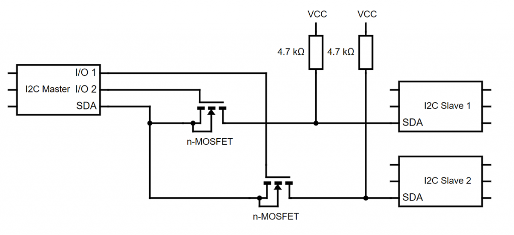
If the MOSFET locks, the SDA line must still be kept on voltage. Any LOW state would be considered an attempt to transmit data. That’s why pull-up resistors are required. Here is a scheme:
I have set myself the goal of controlling four ADS1115 with two MOSFETs. To achieve this, I used the following circuit:

I first tried with the I2C scanner and a single MOSFET if I could access the ADS1115 modules behind the MOSFET. I had chosen an IRF540 as MOSFET. I found out that this only worked with an additional 10 kOhm pull-up and only at 100 kHz. At 400 kHz I even needed 2.2 kOhm pull-ups. The reason for this is the capacitance of the MOSFET. A rough calculation: the IRF540 has an output capacitance of roughly 1200 pF = 1.2×10⁻⁹ F at 5 volts. Die charging time τ of a capacitor depends on its capacitance C and the resistance R (10 kOhm in this case):
![\[ \tau = C\cdot R=1.2\cdot10^{-9}\cdot 10^4=1.2\cdot10^{-5}\;[\text{s}] \]](https://wolles-elektronikkiste.de/wp-content/ql-cache/quicklatex.com-13dfd290353003c148de8f33c764c174_l3.png "Rendered by QuickLaTeX.com")
After 1 τ the capacitor is charged at 63 %. At a frequency of 100 kHz the HIGH level has to be reached latest after 10-5 s after it was LOW. Obviously, that does not work. With two parallel pull-ups of 10 kOhm it barely worked. I could see this on the oscilloscope. First without MOSFET:
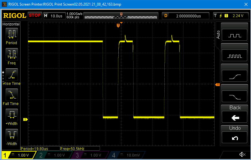
And this is how it looked like with an IRF540 and the two 10 kOhm pull-ups:

Thus, you should choose small MOSFETs like a 2N7000 or a BS170. Their capacitance is a small fraction compared to the IRF540.
With microcontrollers running at 3.3 volts, you might get into trouble as it gets tight with the necessary gate voltage.
Now to the sketch: Since in this example there are two ADS1115 on one line, two different I2C addresses have to be used. Otherwise, there is nothing new, except that the channels are switched via the pins 8 and 9.
#include<ADS1115_WE.h>
#include<Wire.h>
#define AD1115_I2C_ADDRESS_A  0x48
#define AD1115_I2C_ADDRESS_B  0x49
#define I2C_CHANNEL_0_PIN     8
#define I2C_CHANNEL_1_PIN     9

ADS1115_WE adc[4];

void setup() {
  Wire.begin();
  Serial.begin(9600);
  pinMode(I2C_CHANNEL_0_PIN, OUTPUT);
  pinMode(I2C_CHANNEL_1_PIN, OUTPUT);

  setI2CChannel(0);
  adc[0] =  ADS1115_WE(AD1115_I2C_ADDRESS_A);
  setupAdc(0);
  adc[1] =  ADS1115_WE(AD1115_I2C_ADDRESS_B);
  setupAdc(1);

  setI2CChannel(1);
  adc[2] =  ADS1115_WE(AD1115_I2C_ADDRESS_A);
  setupAdc(2);
  adc[3] =  ADS1115_WE(AD1115_I2C_ADDRESS_B);
  setupAdc(3);
}

void loop() {
  float voltage = 0.0;

  for(int i=0; i<4; i++){
    if(i<2){
      setI2CChannel(0);
    }
    else{
      setI2CChannel(1);
    }
    voltage = adc[i].getResult_V();
    Serial.print("Voltage [V], ADS1115 No ");
    Serial.print(i);
    Serial.print(": ");
    Serial.println(voltage);
  }
  Serial.println("****************************");
  delay(1000);
}

void setI2CChannel(byte i){
  if(i==0){
    digitalWrite(I2C_CHANNEL_1_PIN, LOW);
    digitalWrite(I2C_CHANNEL_0_PIN, HIGH);
  }
  else if(i==1){
    digitalWrite(I2C_CHANNEL_0_PIN, LOW);
    digitalWrite(I2C_CHANNEL_1_PIN, HIGH);
  }
}

void setupAdc(byte i){
  if(!adc[i].init()){
      Serial.print("ADS1115 No ");
      Serial.print(i);
      Serial.println(" not connected!");
    }
    adc[i].setVoltageRange_mV(ADS1115_RANGE_6144);
    adc[i].setCompareChannels(ADS1115_COMP_0_GND);
    adc[i].setMeasureMode(ADS1115_CONTINUOUS);
}
Again, there would be potential for simplification because at least two ADS1115 are identical in this example.
Acknowledgement
The Fritzing components ADS1115 and TCA9546A come from Adafruit. If you are also looking for Fritzing components, then you have a great chance to find them here.