
About the post
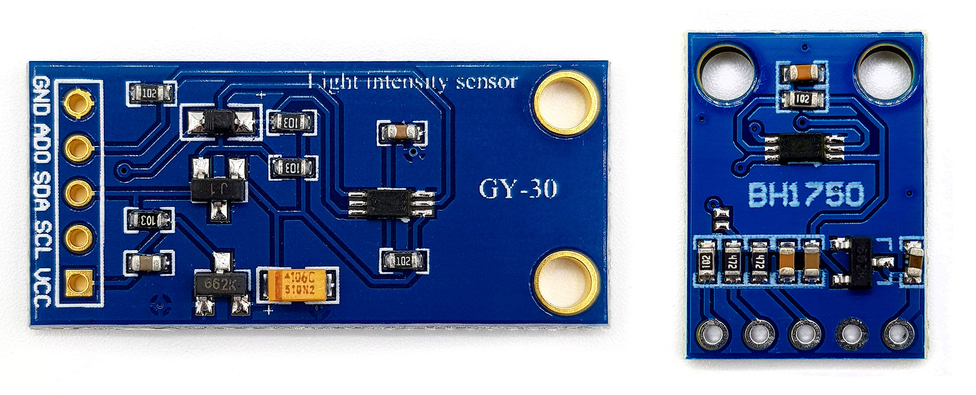
In this article of my series1 about light, gesture, motion and distance sensors I would like to introduce the ambient light sensor BH1750FVI. More specifically, it is about the BH1750FVI module – the BH1750FVI itself is the small six-pin IC on the module. Often you can also find the abbreviation BH1750 or even only GY-302 or GY-30, but this is always the same module or at least the same base.
A few posts ago, I presented the light sensor TSL2561, which at first glance works similarly to the BH1750FVI, but has a clear difference in detail. A comparison of this and all other sensors in this series is available when I have completed the series.
In this article, I will first discuss the technical features, present the setting options, explain the control via Arduino and present my library for this module. There are already a number of libraries for the BH1750FVI, but I haven’t found one where the setting of the measurement time was implemented or worked according to my expectations.
1 A summary of the series can be found here.
Properties
Principle
The BH1750FVI has a photodiode with a response range of approx. 400 – 700 nm, i.e. essentially the area of visible light. The photo voltage is amplified and stored with an A/D converter in a 16-bit reading. The measured value are integrated over an adjustable measurement period.
Specifications of the BH1750FVI module
The most important technical data are:
- Power supply: 3 – 5 VDC
- Current Consumption: x 0.14 mA
- Power Off Mode: 0 mA
- Communication: I2C (SDA/SCL)
- I2C addresses: 0x23 or 0x5C adjustable
- Measuring range: 0 – 65535 lx, expandable up to 100000 (according to data sheet)
- in my view, the values are not quite right – more on that later.
- Maximum resolution: depending on the setting 0.11 – 7.4 lx
The standard I2C address of the module is 0x23. You can change it to 0x5C by connecting the address pin (ADDR or ADD) to HIGH. The pin is apparently “pulled down”. Therefore, no connection to GND is necessary for the use of the default address. You can check the address with an I2C scanner, for example the one here.
You can buy the module for about 2 euros, e.g. at Amazon from numerous providers.
You can get a detailed data sheet here.
Setting options / operating modes
Resolution modes
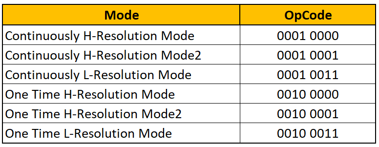
The BH1750HVI has three continuous and three discontinuous (“One Time”) modes:
- Continuously H-Resolution Mode
- Continuously H-Resolution Mode2
- Continuously L-Resolution Mode
- One Time H-Resolution Mode
- One Time H-Resolution Mode2
- One Time L-Resolution Mode
The advantage of the “One Time” modes is that the module automatically goes into Power Off mode after the measurement and thus saves power.
Otherwise, the modes differ in terms of resolution and measurement time:

The continuous H-Resolution Mode is the default. You go into L-Resolution Mode if you want to measure fast or at high frequency. The H-Resolution Mode2 is a good way to achieve a higher resolution in the dark.
Resolution vs maximum light intensity
The measured value is stored as a 16 bit value, correspondingly 65535 is the maximum value. To convert the measured values into Lux, the raw data in H-Resolution and L-Resolution Mode must be divided by 1.2, according to the data sheet. This results in a maximum value of 54612 lx. In H-Resolution Mode2, the result must be divided by two again. This results in a maximum value of 27306 lx.
How to set the modes
If you are not using a library, you only need to send a single control byte (called OpeCode in the data sheet) to the BH1750HVI via I2C to set the desired mode. Later you can see in the example sketches how this works in detail.
Setting the measurement time
Frankly, I had to read the section on the setting procedure of the measurement time several times because it is, let’s say, unusual. First, one should know that the setting of the measuring time is relative to the basic measurement time set by the mode, i.e. 16 or 120 ms. This means that you do not specify a value in milliseconds, but work with factors.
The measurement time or factor is set in the Measurement Time Register (MTReg). The default setting is 69 (0b01000101). This value can be varied from 31 to 254. A change to 31 means:
New measurement time = base value x 31/69 ≈ base value x 0,45
A change to the maximum value 254 means:
New measurement time = base value x 254/69 ≈ base value x 3,68
The measuring time can be changed by a factor of 0.45 to 3.68.
The measurement time change is directly proportional to the raw data. Accordingly, the maximum measurable light intensity changes. For example, in Continuous H mode, the maximum measurable Lux value is 65535 / 1.2 ≈ 54612. If the measuring time is reduced to the 0.45fold, the light can be correspondingly more intense without the 16-bit data register overflowing. The maximum measurable value in Lux is thus 65535 x (69/31) / 1.2 ≈ 121557 lx. I don’t know why the data sheet specifies 100000 lx as the maximum value.
It is important to take the factors into account when converting the raw data into lux values, otherwise the results are wrong. However, there may also be a reason not to do this, and that is when you are performing a calibration. More on that.
Why change the measurement time?
There are three reasons to change the measurement time:
- Expanding the measuring range upwards
- Ensure a higher resolution a low values
- Calibration, e.g. due to the use of a window that absorbs part of the light
Let’s say the BH1750FVI is installed behind a window that only passes through 50% of the light. In this case, the measuring time would be doubled to compensate for the effect (calibration). And in this case, of course, the factor would not be factored out at the end, as in 1 and 2.
Resolution versus measurement time
Derived from the calculation rules given above, the resolution can be determined depending on the MTReg value:
Resolution in H-Resolution Mode = 1/1.2 x 69/MTReg
Resolution in H-Resolution Mode2 = (1/1.2 x 69/MTReg)/2
Resolution in L-Resolution Mode = (1/1.2 x 69/MTReg) x 4
This results in:

How to change the measurement time
In principle, I have already given the answer. You need to change the default value in MTReg from 69 to the desired value. If you have a library that has implemented this feature, you don’t have to worry about the details and can skip the rest of the section.
For those who work without a library or want to change something in their library or just want to know what’s going on behind the scenes, I’ll explain that.
You are normally used to changing a register value by addressing a control register, passing the destination register address, and then sending the values byte by byte. Things are a little different here. The three upper bits and the five lower bits of the MTReg value (short: MTReg) are passed to the BH1750FVI in two steps, packaged in two control bytes. This happens according to the following scheme:
- Byte1 = 01000 [MTReg Bit7] [MTReg Bit6] [MTReg Bit5]
- Byte2 = 011 [MTReg Bit4] [MTReg Bit3] [MTReg Bit2] [MTReg Bit1] [MTReg Bit0]
The best way to calculate the bytes is by binary operations:
Byte1 = (MTReg >> 5) | 0b01000000
The 5 digit shift positions the bits 7,6 and 5 in the correct position. The subsequent logical OR operation ensures that the lower bits remain unchanged and the higher bits are 01000.
Byte2 = (MTReg & 0b01111111) | 0b01100000
Here, the first logical AND ensures write a 0 in bit 7 of the byte2 without changing the other bits. The subsequent OR operation sets bits 6 and 7 without changing the other bits.
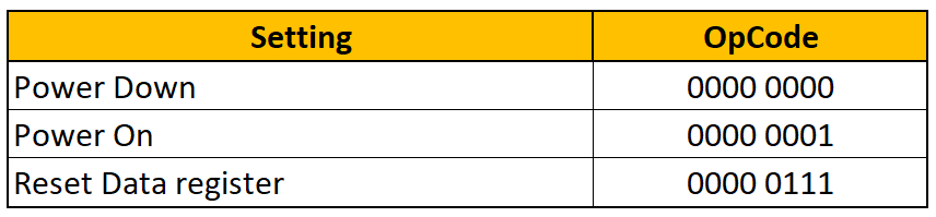
Other settings
Here are a few more settings with the corresponding OpeCodes:
Control of the BH1750FVI without library
The sketch
Here is the Arduino Sketch for controlling the BH1750FVI without a library.
The MTReg value (measuringTimeFactor) is entered as a factor and the byte value for the MT register is calculated from it. I find this more practical than setting the MTReg value directly. In line 38 and 41, the factor is factored out again to get the “real” Lux values. If the factor is used for calibration, this calculation step must be omitted.
Based on the previous explanations, the sketch should be self-explanatory.
#include <Wire.h>
#define BH_1750 0x23
#define DATA_REG_RESET 0b00000111
#define POWER_DOWN 0b00000000
#define POWER_ON 0b00000001

enum BH1750Mode {
  CHM = 0b00010000,     //CHM: Continuously H-Resolution Mode
  CHM_2 = 0b00010001,   //CHM_2: Continuously H-Resolution Mode2
  CLM = 0b00010011,     //CLM: Continuously L-Resolution Mode
  OTH = 0b00100000,     //OTH: One Time H-Resolution Mode
  OTH_2 = 0b00100001,   //OTH_2: One Time H-Resolution Mode2
  OTL = 0b00100011      //OTL: One Time L-Resolution Mode
} mode;

float measuringTimeFactor;

void setup(){
  Serial.begin(9600);
  Wire.begin();
  mode = CHM;
  measuringTimeFactor = 1;
  setMode();
  setMeasuringTime();
  delay(200);
}

void loop(){
  getLux();
  delay(1000);
}

void getLux(){
  uint16_t rawLux;
  float lux;
  rawLux = readBH1750();
  if((mode==CHM_2)||(mode==OTH_2)){
    lux = (rawLux/2.4)/measuringTimeFactor;
  }
  else{
    lux = (rawLux/1.2)/measuringTimeFactor;
  }
  Serial.print(F("Lichtstärke: "));
  Serial.print(lux);
  Serial.println(F(" Lux"));
}

void powerDown(){
  writeBH1750(POWER_DOWN);
}

void powerOn(){
  writeBH1750(POWER_ON);
  setMode();
}

void dataRegReset(){
  writeBH1750(DATA_REG_RESET);
}

void setMode(){
  writeBH1750(mode);
}

void setMeasuringTime(){
  byte mt = round(measuringTimeFactor*69);
  byte highByteMT = ((mt>>5) | 0b01000000);
  byte lowByteMT = (mt & 0b01111111);
  lowByteMT |= 0b01100000;
  writeBH1750(highByteMT);
  writeBH1750(lowByteMT);
}

uint16_t readBH1750(){
  uint8_t MSbyte, LSbyte;
  Wire.requestFrom(BH_1750, 2);
  if(Wire.available()){
    MSbyte=Wire.read();
    LSbyte=Wire.read();
  }
  return ((MSbyte<<8) + LSbyte);
}

void writeBH1750(byte val){
  Wire.beginTransmission(BH_1750);
  Wire.write(val);
  Wire.endTransmission();
}
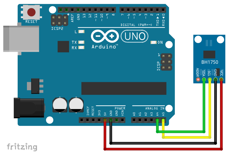
Wiring
For completeness, here is the circuit, even if it is anything but complex. It should be noted that I did not use pull-up resistors for the SDA / SCL lines. It also works without. If you get problems, add them.
BH1750FVI Library
Since, as already mentioned, I did not find a library where the setting of the measurement time was implemented to my satisfaction, I wrote my own. It’s called BH1750_WE and you’ll find it here on Github. If you want to work with it, download it as a zip file and unpack it in the Arduino/libraries folder. The following example sketch can be found in the example folder. (New: you can now also install the library directly via the library manager in the Arduino IDE).
/***************************************************************************
* Example sketch for the BH1750_WE library
*
* Mode selection / abbreviations:
* CHM:    Continuously H-Resolution Mode
* CHM_2:  Continuously H-Resolution Mode2
* CLM:    Continuously L-Resolution Mode
* OTH:    One Time H-Resolution Mode
* OTH_2:  One Time H-Resolution Mode2
* OTL:    One Time L-Resolution Mode
*
* Measuring time factor:
* 1.0 ==> Mresuring Time Register = 69
* 0.45 ==> Measuring Time Register = 31
* 3.68 ==> Mesuring Time Register = 254
*
* Other implemented functions, not used in the example:
* resetDataReg() --> rests Data Register
* powerOn() --> Wake Up!
* powerDown() --> Sleep well, my BH1750
*
* If you change the measuring time factor for calibration purpose,
* then you need to devide the light intensity by the measuring time factor
*
* Further information can be found on:
* https://wolles-elektronikkiste.de/en/bh1750fvi-gy-30-302-ambient-light-sensor
* or in German:
* https://wolles-elektronikkiste.de/bh1750fvi-lichtsensormodul
***************************************************************************/

#include <Wire.h>
#include <BH1750_WE.h>
#define BH1750_ADDRESS 0x23

BH1750_WE myBH1750(BH1750_ADDRESS);
// You may also pass a TwoWire object like wire2
// BH1750_WE myBH1750(&wire2, BH1750_ADDRESS);

void setup(){
  Serial.begin(9600);
  Wire.begin();
  myBH1750.init(); // sets default values: mode = CHM, measuring time factor = 1.0
  // myBH1750.setMode(CLM);  // uncomment if you want to change default values
  // myBH1750.setMeasuringTimeFactor(0.45); // uncomment for selection of value between 0.45 and 3.68
}

void loop(){
  float lightIntensity = myBH1750.getLux();
  Serial.print(F("Lichtstärke: "));
  Serial.print(lightIntensity);
  Serial.println(F(" Lux"));
  delay(1000);
}
Measurements in One Time Modes
For measurements in one time modes, please note that setMode() starts the measurement. You have to wait until the measurement is complete, and then you can read out the new measured value. According to the data sheet, a measurement in OTH modes takes approx. 120 milliseconds, in OTL mode it takes 16 milliseconds.
#include <Wire.h>
#include <BH1750_WE.h>
#define BH1750_ADDRESS 0x23

BH1750_WE myBH1750 = BH1750_WE(BH1750_ADDRESS);
// You may also pass a TwoWire object:
//BH1750_WE myBH1750 = BH1750_WE(&Wire, BH1750_ADDRESS);
// If you don't pass any parameter, Wire and 0x23 will be applied

void setup(){
  Serial.begin(9600);
  Wire.begin();
  if(!myBH1750.init()){ // sets default values: mode = CHM, measuring time factor = 1.0
    Serial.println("Connection to the BH1750 failed");
    Serial.println("Check wiring and I2C address");
    while(1){}
  }
  else{
    Serial.println("BH1750 is connected");
  }
  // myBH1750.setMeasuringTimeFactor(0.45); // uncomment for selection of value between 0.45 and 3.68
}

void loop(){
  myBH1750.setMode(OTH); // sets mode and starts measurement
  /* An OTH and OTH_2 measurement takes ~120 ms. I suggest to wait
     140 ms to be on the safe side.
     An OTL measurement takes about 16 ms. I suggest to wait 20 ms
     to be on the safe side. */
  delay(140); // wait for measurement to be completed.
  float lightIntensity = myBH1750.getLux();
  Serial.print(F("Light intensity: "));
  Serial.print(lightIntensity);
  Serial.println(F(" Lux"));
  delay(1000);
}
Acknowledgement
The background for the post image is by Hanna Kovalchuk on Pixabay.
I took the BH1750FVI as Fritzing component from vdemay on Github.
Sir, you are a hero. From all the libraries I’ve visited, yours is the only one that convinced me and is properly documented. If this works on an spectrophotometer and the result is neat, I’ll make sure to thank you in the acknowledgements. Also, I’m looking for more info about the OTH_2 modes, as to configure it for a measuring cycle. Plus, I’m using the idea of the 2 BH1750 to wire more than 2 BH1750 switching which one is the “ON” one. Although I would still need more info as to what minimum delay is needed for this live switch to work properly.
Hi, thanks for your comment, feels good! For the OTH_2 I think I can’t provide more information than I have shared in this article and what is mentioned in the data sheet. If you want to use more than two BH1750, than you have an I2C address conflict. In theory you can switch them on and off and use the same address. The more convenient solution is an I2C multiplexer like this one:
https://www.aliexpress.com/item/32904755017.html?spm=a2g0o.productlist.0.0.55d5cd8bcSpRTG&algo_pvid=b8f350dc-5f5c-4410-8f82-51b120d85bbb&algo_expid=b8f350dc-5f5c-4410-8f82-51b120d85bbb-0&btsid=0b0a050b16185008827266049e65dc&ws_ab_test=searchweb0_0,searchweb201602_,searchweb201603_
I have not tried it but from what I read in the net it’s working fine. Found this tutorial:
https://tronixstuff.com/2019/10/29/tutorial-using-the-tca9548a-1-to-8-i2c-multiplexer-breakout-with-arduino/
Another potential solution which I still want to try (but my to-do list is long) is to connect several I2C devices to one bus, but each connected on the SDA line via a transistor which I use as a switch. Then, in theory the I2C line to the device can be switch on and off. But the safer route is the multiplexer.
Thank you so much! I searched a way to read data from two BH1750 on different I2C addresses and your description of control of the BH1750FVI without library helps to me. It would be grateful if you can add the same functions in your lib.
It should be possible using the library. It would look like this:
#define BH1750_ADDRESS_1 0x23
#define BH1750_ADDRESS_2 0x5C
BH1750_WE myBH1750_1(BH1750_ADDRESS_1);
BH1750_WE myBH1750_2(BH1750_ADDRESS_2);
Then you can “speak” to both modules seperately by calling the functions with either myBH1750_1 or myBH1750_2.