About the post
This post is part of a series about light, gesture, motion and distance sensors. I will complete it with a general overview ( here). After my last post about the APDS-9960, this one will be about light sensor module TSL2561. I will first go into the properties and then explain how to control it using the Sparkfun library.
Properties of the TSL2561
The TSL2561 converts the light intensity via two photo diodes and downstream analog-digital converters into digital 16-bit values that can be read out via I2C. One of the photodiodes (Channel 0) covers the visible wavelength range plus infrared, the other (Channel 1) only covers the infrared range. The measurements of the two channels are carried out in parallel. The output data can be converted into lux values using an empirical formula. Strictly speaking, it is a whole collection of formulas that are used according to the lighting conditions. By considering the IR component, the light values correspond particularly well to the perception of the human eye.
Measurement parameters of the TSL2561
The light measurement takes place integrally, i.e. the photodiode currents are added over a certain period of time. Three predefined measurement times (referred to as “Integration time” in the data sheet) can be set in the timing register:
- 13.7 ms
- 101 ms
- 402 ms
There is also the option of a manual measurement, which can be set via a specific bit in the timing register. “1” starts the measurement, “0” ends it. But don’t worry, you don’t have to deal with the registers in detail, because you can easily make the settings using the convenient functions of the Sparkfun library.
The two gain factors 1x or 16x can be selected in the timing register. The longer the measurement time and the higher the gain factor, the larger the raw data from the two channels. In this way you can use the register width optimally, but you also have to be careful not to create an overflow, i.e. values greater than / equal to 2 16 = 65536.
Interrupt functions of the TSL2561
The TSL2561 has an active-low interrupt output. An upper and a lower threshold can be specified at which an interrupt is triggered. The interrupt thresholds relate to the values of channel 0. They are therefore dependent on the measuring times and the gain factor and do not relate to absolute lux values.
The interrupt function can be switched on or off in the interrupt control register. In addition, the following options can be selected:
- Interrupt after every measurement, regardless of limits
- Interrupt after x measurements outside the limits with x = 1 to 15
The interrupt remains until the CLEAR bit is set in the command register.
If you want to know more details about the TSL2561, take a look at the data sheet, which is available here, for example.
The TSL2561 module
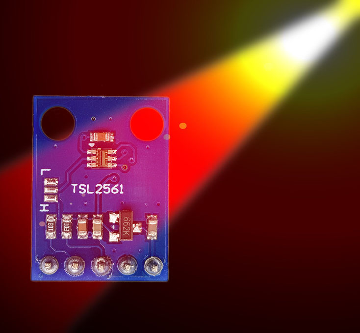
The purchase of a TSL2561 module vs. the bare TSL2561 IC is ideal for the normal hobby electronics technician who does not feel like soldering SMD components. You can get this for a few euros, e.g. here at Amazon. Most of these modules look like this:

It is important that the component should be operated in the range from 2.7 to 3.6 volts. On the Arduino UNO you can use the 3.3 volt output for the power supply. However, the I2C lines are still at 5 volts level. Therefore you either take a microcontroller that runs on 3.3 volts or you build a voltage divider in the lines or you use a level converter, which you can buy for about 1 euro per piece, e.g. here.
You can set three different I2C addresses. Without further precautions, the address is 0x39. If you connect contact “L” to the middle contact in the jumper area on the module, the address changes to 0x29. If you connect “H” to the middle contact, the address is 0x49.
If you want to check the I2C address, then you will find here a scanner sketch. This is always a good starting point to check your circuit and if the I2C component is working.
Wiring of the TSL2561
The wiring is no surprise:
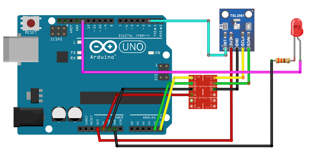
The level converter must be power supplied at least on the 5 volt side. If there are any difficulties, connect the 3.3 volts side as well. Pull-up resistors for the I2C lines were not necessary because the level converter acts as a pull-up (another argument for level converters). For one of the example sketches we still need a line from the interrupt output of the module to Arduino pin D2 and an LED at D13.
The Sparkfun library for the TSL2561
I chose the TSL2561_Luminosity_Sensor_BOB library from Sparkfun because it implemented all the important functions. There is also a library from Adafruit, but the interrupt functions are missing there (at least as things stand today).
Sparkfun’s library is here available on Github. It has now been archived because Sparkfun has removed the module from its program. But that is not a problem.
Interrupt problems with the Sparkfun library
While trying it out, I noticed that the interrupt function was implemented but didn’t work. I was able to identify the reason for the error, reported it, and they changed the library accordingly. But since there is still a version in which the error has not been corrected (SparkFun_TSL2561_Arduino_Library), it is better to follow the link above and do not search manually on Github.
The only disadvantage of the corrected version is that after downloading and unzipping the zip file you still have to move everything in the directory under TSL2561_Luminosity_Sensor_BOB_master / Libraries / Arduino directly to TSL_Luminosity_Sensor_BOB_master. Otherwise, the src folder is located “too deep” and the Arduino IDE will not find it.
If you already have a version that has problems with the interrupt, then take a look at line 266 of the library file SparkFunTSL2561.cpp. It says there:
if (writeByte(TSL2561_REG_INTCTL,((control | 0B00000011) << 4) & (persist | 0B00001111)))
then replace the line with:
if (writeByte(TSL2561_REG_INTCTL,((control & 0B00000011) << 4) | (persist & 0B00001111)))
and it should work.
If all of this is too complicated for you and you don’t need the interrupt function, you can also use the Adafruit library to fall back on. Should you decide to take this path, I recommend taking a look into Adafruit’s Tutorial.
The Sparkfun example sketch for the TSL2561
I have taken the example sketch as is. It provides the raw data from the two channels and the lux values calculated from them. With the information in this post and the comments in the sketch, it probably doesn’t need any further explanations, except perhaps that the address jumpers on the Sparkfun module are labeled “0” and “1” and not “L” and “H” (see line 70-76).
/* SparkFun TSL2561 library example sketch

This sketch shows how to use the SparkFunTSL2561
library to read the AMS/TAOS TSL2561
light sensor.

Product page: https://www.sparkfun.com/products/11824
Hook-up guide: https://learn.sparkfun.com/tutorials/getting-started-with-the-tsl2561-luminosity-sensor

Hardware connections:

3V3 to 3.3V
GND to GND

(WARNING: do not connect 3V3 to 5V
or the sensor will be damaged!)

You will also need to connect the I2C pins (SCL and SDA) to your Arduino.
The pins are different on different Arduinos:

                    SDA    SCL
Any Arduino         "SDA"  "SCL"
Uno, Redboard, Pro  A4     A5
Mega2560, Due       20     21
Leonardo            2      3

You do not need to connect the INT (interrupt) pin
for basic operation.

Operation:

Upload this sketch to your Arduino, and open the
Serial Monitor window to 9600 baud.

Have fun! -Your friends at SparkFun.

Our example code uses the "beerware" license.
You can do anything you like with this code.
No really, anything. If you find it useful,
buy me a beer someday.

V10 Mike Grusin, SparkFun Electronics 12/26/2013
Updated to Arduino 1.6.4 5/2015
*/

// Your sketch must #include this library, and the Wire library
// (Wire is a standard library included with Arduino):

#include <SparkFunTSL2561.h>
#include <Wire.h>

// Create an SFE_TSL2561 object, here called "light":

SFE_TSL2561 light;

// Global variables:

boolean gain;     // Gain setting, 0 = X1, 1 = X16;
unsigned int ms;  // Integration ("shutter") time in milliseconds

void setup()
{
  // Initialize the Serial port:

  Serial.begin(9600);
  Serial.println("TSL2561 example sketch");

  // Initialize the SFE_TSL2561 library

  // You can pass nothing to light.begin() for the default I2C address (0x39),
  // or use one of the following presets if you have changed
  // the ADDR jumper on the board:

  // TSL2561_ADDR_0 address with '0' shorted on board (0x29)
  // TSL2561_ADDR   default address (0x39)
  // TSL2561_ADDR_1 address with '1' shorted on board (0x49)

  // For more information see the hookup guide at: https://learn.sparkfun.com/tutorials/getting-started-with-the-tsl2561-luminosity-sensor

  light.begin();

  // Get factory ID from sensor:
  // (Just for fun, you don't need to do this to operate the sensor)

  unsigned char ID;

  if (light.getID(ID))
  {
    Serial.print("Got factory ID: 0X");
    Serial.print(ID,HEX);
    Serial.println(", should be 0X5X");
  }
  // Most library commands will return true if communications was successful,
  // and false if there was a problem. You can ignore this returned value,
  // or check whether a command worked correctly and retrieve an error code:
  else
  {
    byte error = light.getError();
    printError(error);
  }

  // The light sensor has a default integration time of 402ms,
  // and a default gain of low (1X).

  // If you would like to change either of these, you can
  // do so using the setTiming() command.

  // If gain = false (0), device is set to low gain (1X)
  // If gain = high (1), device is set to high gain (16X)

  gain = 0;

  // If time = 0, integration will be 13.7ms
  // If time = 1, integration will be 101ms
  // If time = 2, integration will be 402ms
  // If time = 3, use manual start / stop to perform your own integration

  unsigned char time = 2;

  // setTiming() will set the third parameter (ms) to the
  // requested integration time in ms (this will be useful later):

  Serial.println("Set timing...");
  light.setTiming(gain,time,ms);

  // To start taking measurements, power up the sensor:

  Serial.println("Powerup...");
  light.setPowerUp();

  // The sensor will now gather light during the integration time.
  // After the specified time, you can retrieve the result from the sensor.
  // Once a measurement occurs, another integration period will start.
}

void loop()
{
  // Wait between measurements before retrieving the result
  // (You can also configure the sensor to issue an interrupt
  // when measurements are complete)

  // This sketch uses the TSL2561's built-in integration timer.
  // You can also perform your own manual integration timing
  // by setting "time" to 3 (manual) in setTiming(),
  // then performing a manualStart() and a manualStop() as in the below
  // commented statements:

  // ms = 1000;
  // light.manualStart();
  delay(ms);
  // light.manualStop();

  // Once integration is complete, we'll retrieve the data.

  // There are two light sensors on the device, one for visible light
  // and one for infrared. Both sensors are needed for lux calculations.

  // Retrieve the data from the device:

  unsigned int data0, data1;

  if (light.getData(data0,data1))
  {
    // getData() returned true, communication was successful

    Serial.print("data0: ");
    Serial.print(data0);
    Serial.print(" data1: ");
    Serial.print(data1);

    // To calculate lux, pass all your settings and readings
    // to the getLux() function.

    // The getLux() function will return 1 if the calculation
    // was successful, or 0 if one or both of the sensors was
    // saturated (too much light). If this happens, you can
    // reduce the integration time and/or gain.
    // For more information see the hookup guide at: https://learn.sparkfun.com/tutorials/getting-started-with-the-tsl2561-luminosity-sensor

    double lux;    // Resulting lux value
    boolean good;  // True if neither sensor is saturated

    // Perform lux calculation:

    good = light.getLux(gain,ms,data0,data1,lux);

    // Print out the results:

    Serial.print(" lux: ");
    Serial.print(lux);
    if (good) Serial.println(" (good)"); else Serial.println(" (BAD)");
  }
  else
  {
    // getData() returned false because of an I2C error, inform the user.

    byte error = light.getError();
    printError(error);
  }
}

void printError(byte error)
  // If there's an I2C error, this function will
  // print out an explanation.
{
  Serial.print("I2C error: ");
  Serial.print(error,DEC);
  Serial.print(", ");

  switch(error)
  {
    case 0:
      Serial.println("success");
      break;
    case 1:
      Serial.println("data too long for transmit buffer");
      break;
    case 2:
      Serial.println("received NACK on address (disconnected?)");
      break;
    case 3:
      Serial.println("received NACK on data");
      break;
    case 4:
      Serial.println("other error");
      break;
    default:
      Serial.println("unknown error");
  }
}
An example sketch using the interrupt function
I have changed the example sketch so that an upper and lower interrupt threshold is defined. If an interrupt is triggered, there is a corresponding message in the serial monitor and the LED connected to pin D13 lights up for one second.
#include <SparkFunTSL2561.h>
#include <Wire.h>

SFE_TSL2561 light;

boolean gain;     // Gain setting, 0 = X1, 1 = X16;
unsigned int ms;  // Integration ("shutter") time in milliseconds
byte interruptPin = 2;
byte ledPin = 13;
volatile bool event = false;


void setup()
{
  pinMode(ledPin, OUTPUT);
  pinMode(interruptPin, INPUT_PULLUP);
  attachInterrupt(digitalPinToInterrupt(interruptPin), blink, FALLING);
  Serial.begin(9600);
  Serial.println("TSL2561 example sketch with interrupts");

  light.begin();

  // If gain = false (0), device is set to low gain (1X)
  // If gain = high (1), device is set to high gain (16X)

  gain = 0;

  // If time = 0, integration will be 13.7ms
  // If time = 1, integration will be 101ms
  // If time = 2, integration will be 402ms
  // If time = 3, use manual start / stop to perform your own integration

  unsigned char time = 1;

  Serial.println("Set timing...");
  light.setTiming(gain, time, ms);
  Serial.print("ms: "); Serial.println(ms);

  // Sets up interrupt operations: setInterruptControl(control/persist)
  // If control = 0, interrupt output disabled
  // If control = 1, use level interrupt, see setInterruptThreshold()
  // If persist = 0, every integration cycle generates an interrupt
  // If persist = 1, any value outside of threshold generates an interrupt
  // If persist = 2 to 15, value must be outside of threshold for 2 to 15 integration cycles

  if (light.setInterruptControl(1, 2)) { //control=1, persist=2
    Serial.println("Interrupt Control: success");
  }
  if (light.setInterruptThreshold(150, 5000)) {
    Serial.println("Interrupt threshold set");
  }
  light.clearInterrupt();

  Serial.println("Powerup...");
  light.setPowerUp();
}

void loop()
{
  unsigned int data0, data1;

  if (light.getData(data0, data1))
  {
    Serial.print("data0: ");
    Serial.print(data0);
    Serial.print(" data1: ");
    Serial.print(data1);

    double lux;    // Resulting lux value
    boolean good;  // True if neither sensor is saturated
    good = light.getLux(gain, ms, data0, data1, lux);

    Serial.print(" lux: ");
    Serial.print(lux);
    if (good) Serial.println(" (good)"); else Serial.println(" (BAD)");
  }
  else
  {
    byte error = light.getError();
    printError(error);
  }
  if (event) {
    Serial.println("Interrupt!!");
    digitalWrite(ledPin, HIGH);
    delay(1000);
    digitalWrite(ledPin, LOW);
    event = false;
    light.clearInterrupt();

  }
}

void printError(byte error)
{
  Serial.print("I2C error: ");
  Serial.print(error, DEC);
  Serial.print(", ");

  switch (error)
  {
    case 0:
      Serial.println("success");
      break;
    case 1:
      Serial.println("data too long for transmit buffer");
      break;
    case 2:
      Serial.println("received NACK on address (disconnected?)");
      break;
    case 3:
      Serial.println("received NACK on data");
      break;
    case 4:
      Serial.println("other error");
      break;
    default:
      Serial.println("unknown error");
  }
}

void blink() {
  event = true;
}
Other functions of the Sparkfun library
With setPowerDown() the TSL2561 can be sent to sleep in order to save electricity.
Manual measurements, i.e. with a free choice of the measurement time (integration time), can be controlled using the manualStart () and manualStop () functions.
That’s it
I hope you enjoyed this post and that it will help you develop projects with the TSL2561. I would be happy to receive feedback. Until the next post!