About the post
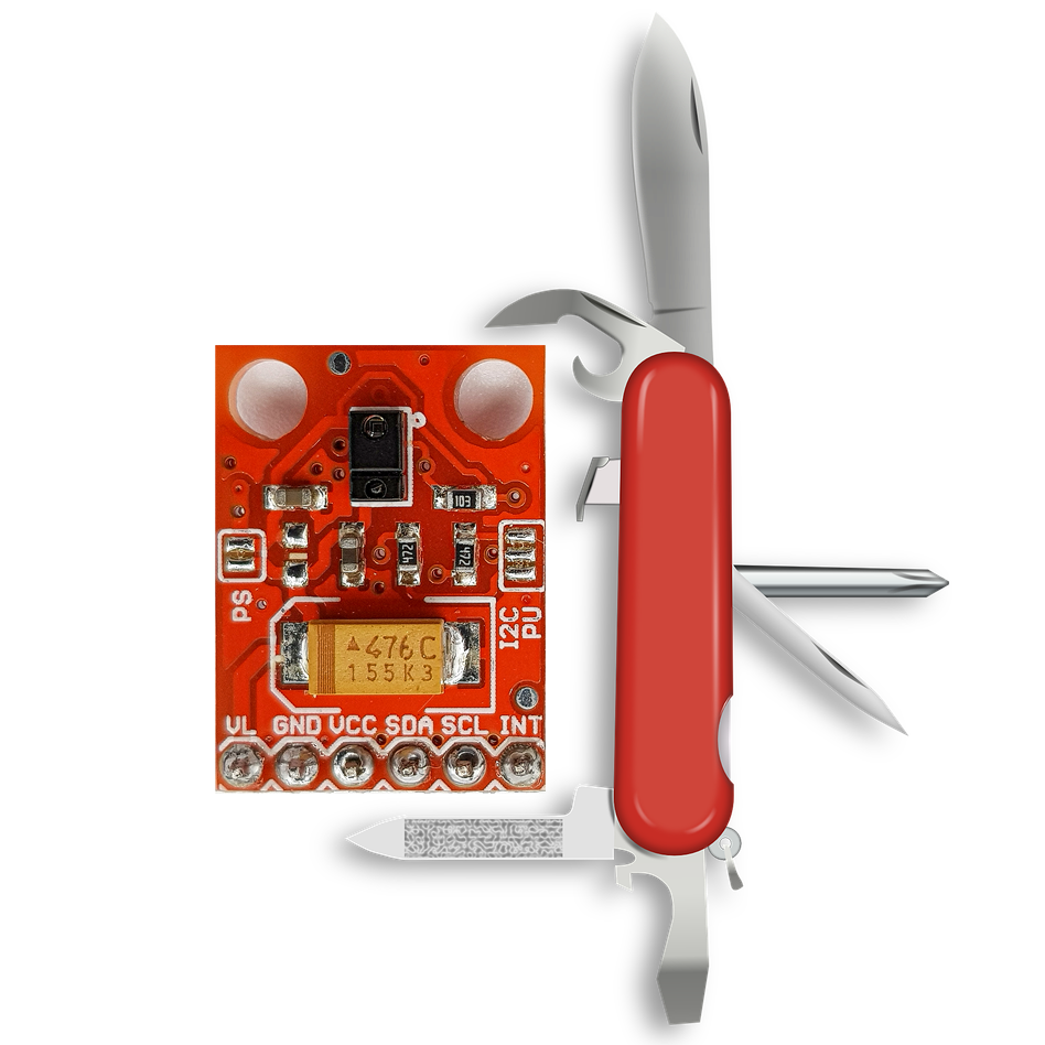
This post about the APDS-9960, more precisely the APDS-9960 module, is the first in a series about distance, motion, color and light sensors (a summary of the series can be found here). The APDS-9960 is the Swiss army knife among these sensors, because it offers:
- Gesture recognition
- Color Recognition (RGB)
- Proximity detection
- Ambient light sensoring
The APDS-9960 can also be used as a motion sensor via proximity detection, but only within its limited working range of up to approx. 30 cm. The following video provides an overview of the various features.
The APDS-9960 has an amazing number of setting options and registers. Implementing this in a sketch is a significant effort. That’s why it’s a good idea to use a ready-made library that has already implemented a number of presets. I will use Sparkfun’s library in this post. I also tried the library of Adafruit and it works just as easily. However, more libraries are available on Github.
Even if you use one of these libraries, I would still advise you to look a little into the data sheet of the APDS-9960 and to deal with the library itself, because not everything that this module is capable of is documented in the examples. In addition, it might make sense for one application or another not to simply adopt the presets but to look for better ones.
Basics of the APDS-9960
The APDS-9960 sensor
The actual APDS-9960 sensor is the small rectangular, black block with the two lens-like openings. The data sheet is available here, for example. From my point of view, it is definitely worth taking a look.

The APDS-9960 has an IR LED whose reflected light is used for gesture and proximity detection. Since it has four directed photodiodes, it is able to detect simple gestures. These photodiodes are also used for proximity detection. Other photodiodes measure red, green, blue, and white light for color and ambient light detection.
Communication with the APDS-9960 is via I2C with a clock rate of up to 400 kHz. The address is set to 0x39 and cannot be changed. Reading the I2C address is always a good first step to check if you have wired everything correctly. An I2C Scanner sketch can be used for this.
The APDS-9960 module

Theoretically, of course, you can buy the bare sensor and add the electronics needed yourself. However, my skills are not sufficient for that and therefore I’m glad that the APDS-9960 is available as a module.
Interestingly, such modules can be purchased from Amazon in two price ranges. One is between three and ten euros and mainly includes manufacturers from China, the other is in the early-mid twenties, e.g. from Sparkfun. I can’t say whether the price difference is justified, as I have only tried some low-cost modules. However, I can at least confirm that the latter have problems with amplification (more on that later). This is also described in other posts, e.g. here.
Most APDS-9960 modules have the following pins:
- GND – Ground
- VCC – Power supply: 2.4 – 3.6 Volt
- SDA/SCL – I2C Connectors
- INT – low active interrupt
- VL – Power supply for IR LED: 3.0 – 4.5 volts
You can supply the APDS-9960 via the 3.3 volt output of an Arduino UNO, but then you still have the problem that the I2C lines run at 5 volts. This can damage the APDS-9960. Therefore, one takes either a microcontroller that is operated with 3.3 volts, such as the ESP-8266, you use voltage dividers or you take level converters, such as this one.
On most modules there are two jumpers, namely “PS” and “I2C PU”:
- PS – if connected, the IR LED is supplied via the voltage to VCC. If not connected, the LED must be supplied separately via VL. It can make sense to leave PS unconnected and switch the LED via VL. According to the data sheet, the IR LED can influence the color and light measurement even though the sensors have an IR filter.
- I2C PU – if connected, the I2C lines are connected to a pull-up resistor, which is quite convenient.
As you can see at the top of the photo of the two APDS-9960 modules, one has closed the jumpers, the other they are open (I bought them like this). So check which version you have.
Wiring: APDS-9960 module controlled by an Arduino UNO
The wiring is no surprise after the previous explanations.
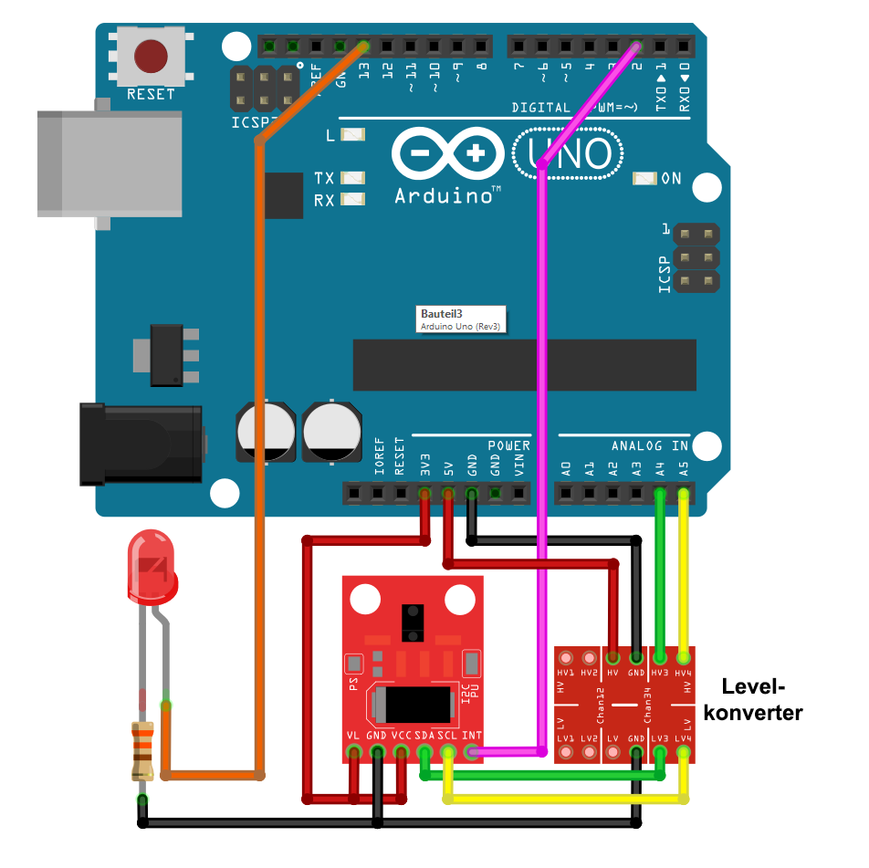
Whether VL – as shown – really needs to be connected to 3.3 V depends, as explained, on the setting of the jumper PS. The I2C lines do not have an external pull-up because the jumper I2C PU was connected. The LED on D13 is required for some example sketches. The same applies to the interrupt output connected to D2. The level converter needs a power supply at least on the 5 volt side.
If it does not work
Der APDS9960 draws around 30 mA current. This can load the 3.3 volt output of an Arduino board to such an extent that the voltage falls below the 3 volts required for the IR_LED. In this case, you can either supply VL with a separate power source or try the 5 volt connection and measure how much voltage is actually provided under load. 3.0 to 4.5 volts is the recommended operating condition. Slightly exceeding 4.5 V should not be a problem. But of course, this is at your own risk.
The Sparkfun library for the APDS-9960
The library is available here on Github. As usual, you download the Zip file and unzip it in the Arduino library folder. There you will also find the example sketches, which I present right away.
Gesture detection
The library implemented the following gestures:
- Up/Down
- Right/Left
- Far/Near
- None
The first two pairs are self-explanatory. A “Far” is reported if you hold the hand very close to the sensor and then remove it vertically to the sensor until it is outside the detection range (approx. 30 cm). For a “Near” one approaches vertically and then pulls the hand to the side. The “Near” is not triggered until the hand has been pulled away. A “none” is reported for ambiguous movements.
In the library, the directions are referred to as DIR_UP, DIR_DOWN, DIR_RIGHT, etc.
The included sample sketch for gesture detection is called GestureTest.ino. I have removed the general comments from the top of the sketchhere. Then I just added the important (!) line 34: apds.setGestureGain(GGAIN_1X). More on that. Otherwise, the sketch is self-explanatory from my point of view.
#include <Wire.h>
#include <SparkFun_APDS9960.h>

// Pins
#define APDS9960_INT    2 // Needs to be an interrupt pin

// Constants

// Global Variables
SparkFun_APDS9960 apds = SparkFun_APDS9960();
int isr_flag = 0;

void setup() {

  // Set interrupt pin as input
  pinMode(APDS9960_INT, INPUT);

  // Initialize Serial port
  Serial.begin(9600);
  Serial.println();
  Serial.println(F("--------------------------------"));
  Serial.println(F("SparkFun APDS-9960 - GestureTest"));
  Serial.println(F("--------------------------------"));

  // Initialize interrupt service routine
  attachInterrupt(digitalPinToInterrupt(APDS9960_INT), interruptRoutine, FALLING);

  // Initialize APDS-9960 (configure I2C and initial values)
  if ( apds.init() ) {
    Serial.println(F("APDS-9960 initialization complete"));
  } else {
    Serial.println(F("Something went wrong during APDS-9960 init!"));
  }
  apds.setGestureGain(GGAIN_1X); // ohne diese Zeile geht es nicht zuverlässig

  // Start running the APDS-9960 gesture sensor engine
  if ( apds.enableGestureSensor(true) ) {
    Serial.println(F("Gesture sensor is now running"));
  } else {
    Serial.println(F("Something went wrong during gesture sensor init!"));
  }
}

void loop() {
  if( isr_flag == 1 ) {
    detachInterrupt(digitalPinToInterrupt(APDS9960_INT));
    handleGesture();
    isr_flag = 0;
    attachInterrupt(digitalPinToInterrupt(APDS9960_INT), interruptRoutine, FALLING);
  }
}

void interruptRoutine() {
  isr_flag = 1;
}

void handleGesture() {
    if ( apds.isGestureAvailable() ) {
    switch ( apds.readGesture() ) {
      case DIR_UP:
        Serial.println("UP");
        break;
      case DIR_DOWN:
        Serial.println("DOWN");
        break;
      case DIR_LEFT:
        Serial.println("LEFT");
        break;
      case DIR_RIGHT:
        Serial.println("RIGHT");
        break;
      case DIR_NEAR:
        Serial.println("NEAR");
        break;
      case DIR_FAR:
        Serial.println("FAR");
        break;
      default:
        Serial.println("NONE");
    }
  }
}
The problem with amplification
The APDS-9960 offers for the detection of gestures the amplification factors 1, 2, 4 and 8, which control the sensitivity of the measurement. In the library, these are called GGAIN_1X, GGAIN_2X, etc. During initialization ( apds.init() ) DEFAULT_GAIN (= GGAIN_4x) is entered in the corresponding control register. Unfortunately, the modules do not cope with this gain factor. This applies at least to the cheap parts, I have obtained from three different Chinese sources. With eight- and four-fold gain it didn’t work at all, with double gain worked unreliably, but without gain (factor 1) it worked wonderfully. It is also not a mistake of the library, since the Adafruit library showed the same behavior. The whole issue took me a lot of time and nerves.
By the way, if you set GGAIN only after apds.enableGestureSensor() and then you start the sketch, the gesture message “None” is triggered for no apparent reason. So better first adjust the gain and then turn on the gesture detection.
Other gesture settings
As already mentioned, one is first overwhelmed by the setting options when looking at the data sheet. But apart from the GGAIN problem, the other presets chosen by the library work very well. Nevertheless, you might also want to “play around” with them. However, not all parameters are accessible through public functions.
- IR-LED current:
setGestureLEDDrive;- the current controls the range of the gesture detection
- 12.5, 25, 50 and 100 mA are possible
- LED_DRIVE_12_5MA, LED_DRIVE_25_MA, etc.
- with 100 mA (default) you achieve a range of 30 cm and the maximum proximity value is at approx. 5 cm distance
- since the IR-LED pulses, the effective power consumption is much lower than the IR-LED current
- IR_LED Boost:
setLEDBoost- private function, not directly accessible
- to change the value, you would have to modify the function
enableGestureSensorin Sparkfun_APDS9960.cpp and edit setLEDBoost or make a public function out of it - Default value is 300, which is already the maximum
- for more details please look into the data sheet
- Pulse length/pulse count of the IR LED:
- not implemented as a function
- variable by changing DEFAULT_GESTURE_PPULSE in Sparkfun_APDS9960.h
- Gesture waiting time:
setGestureWaitTime- controls the time in low power mode between two gesture detection cycles
- 8 values between 0 and 39.2 ms are possible; the parameters in the library are: GWTIME_0MS to GWTIME_39_2MS; default: 2.8 ms
- plus a lot more – > if you really want to know more: look into the library and the data sheet.
Proximity detection
The proximity sensor does not provide distances in centimeters or millimeters, but a value between 0 and 255. The corresponding distance to this value depends, among other things, on the LED current and the gain. The included sample sketch is called ProximitySensor.ino. Here he is, but without the introductory comment lines and with a small change to which I will explain in a while:
#include <Wire.h>
#include <SparkFun_APDS9960.h>

// Global Variables
SparkFun_APDS9960 apds = SparkFun_APDS9960();
uint8_t proximity_data = 0;

void setup() {

  // Initialize Serial port
  Serial.begin(9600);
  Serial.println();
  Serial.println(F("------------------------------------"));
  Serial.println(F("SparkFun APDS-9960 - ProximitySensor"));
  Serial.println(F("------------------------------------"));

  // Initialize APDS-9960 (configure I2C and initial values)
  if ( apds.init() ) {
    Serial.println(F("APDS-9960 initialization complete"));
  } else {
    Serial.println(F("Something went wrong during APDS-9960 init!"));
  }

  // Start running the APDS-9960 proximity sensor (no interrupts)
  if ( apds.enableProximitySensor(false) ) {
    Serial.println(F("Proximity sensor is now running"));
  } else {
    Serial.println(F("Something went wrong during sensor init!"));
  }
  // Adjust the Proximity sensor gain
  if ( !apds.setProximityGain(PGAIN_2X) ) { // muss nach enableProximitySensor aufgerufen werden
    Serial.println(F("Something went wrong trying to set PGAIN"));
  }
}


void loop() {

  // Read the proximity value
  if ( !apds.readProximity(proximity_data) ) {
    Serial.println("Error reading proximity value");
  } else {
    Serial.print("Proximity: ");
    Serial.println(proximity_data);
  }

  // Wait 250 ms before next reading
  delay(250);
}
The change I made is swapping the order of the functions apds.enableProximitySensor and apds.setProximityGain. The latter sets the gain factor (PGAIN_1X, …_2X, … 4X, …_8X) for the proximity sensor. However, in the enable function, the default value is set, namely PGAIN_4X. If you want to change it, you have to do it after the enable function. I reported this little bug on Github as an “issue”, maybe it is already fixed when you install the library.
Other proximity detection settings
The settings are very similar to the settings of the gesture detection:
- IR-LED current:
apds.LEDDrive;- 12.5, 25, 50 and 100 mA are selectable
- IR-LED Boost: identical to IR-LED boost during gesture detection
I don’t want to go more in the details – again I refer to the library and data sheet for those who want to go deeper.
Proximity detection with interrupt
You can set an upper and lower threshold for the proximity value at which an interrupt is triggered. If you set the lower threshold (PROX_INT_LOW) to 0, then only a near-interrupt is triggered, because you never get a 0 due to the noise.
The included example sketch is called ProximityInterrupt.ino. Again, I have moved the function for setting the PGAIN value behind the enable function, otherwise it would be ineffective. Otherwise, the sketch should be self-explanatory.
#include <Wire.h>
#include <SparkFun_APDS9960.h>

// Pins
#define APDS9960_INT    2  // Needs to be an interrupt pin
#define LED_PIN         13 // LED for showing interrupt

// Constants
#define PROX_INT_HIGH   200 // Proximity level for interrupt
#define PROX_INT_LOW    0  // No far interrupt

// Global variables
SparkFun_APDS9960 apds = SparkFun_APDS9960();
uint8_t proximity_data = 0;
int isr_flag = 0;

void setup() {

  // Set LED as output
  pinMode(LED_PIN, OUTPUT);
  pinMode(APDS9960_INT, INPUT);

  // Initialize Serial port
  Serial.begin(9600);
  Serial.println();
  Serial.println(F("---------------------------------------"));
  Serial.println(F("SparkFun APDS-9960 - ProximityInterrupt"));
  Serial.println(F("---------------------------------------"));

  // Initialize interrupt service routine
  attachInterrupt(digitalPinToInterrupt(APDS9960_INT), interruptRoutine, FALLING);

  // Initialize APDS-9960 (configure I2C and initial values)
  if ( apds.init() ) {
    Serial.println(F("APDS-9960 initialization complete"));
  } else {
    Serial.println(F("Something went wrong during APDS-9960 init!"));
  }

   // Set proximity interrupt thresholds
  if ( !apds.setProximityIntLowThreshold(PROX_INT_LOW) ) {
    Serial.println(F("Error writing low threshold"));
  }
  if ( !apds.setProximityIntHighThreshold(PROX_INT_HIGH) ) {
    Serial.println(F("Error writing high threshold"));
  }

  // Start running the APDS-9960 proximity sensor (interrupts)
  if ( apds.enableProximitySensor(true) ) {
    Serial.println(F("Proximity sensor is now running"));
  } else {
    Serial.println(F("Something went wrong during sensor init!"));
  }
   // Adjust the Proximity sensor gain
  if ( !apds.setProximityGain(PGAIN_4X) ) {
    Serial.println(F("Something went wrong trying to set PGAIN"));
  }
}

void loop() {

  // If interrupt occurs, print out the proximity level
  if ( isr_flag == 1 ) {

    // Read proximity level and print it out
    if ( !apds.readProximity(proximity_data) ) {
      Serial.println("Error reading proximity value");
    } else {
      Serial.print("Proximity detected! Level: ");
      Serial.println(proximity_data);
    }

    // Turn on LED for a half a second
    digitalWrite(LED_PIN, HIGH);
    delay(500);
    digitalWrite(LED_PIN, LOW);

    // Reset flag and clear APDS-9960 interrupt (IMPORTANT!)
    isr_flag = 0;
    if ( !apds.clearProximityInt() ) {
      Serial.println("Error clearing interrupt");
    }

  }
}

void interruptRoutine() {
  isr_flag = 1;
}
If you set PROX_INT_LOW to a value bigger than the basic noise, e.g. 50, then you have two thresholds at which an interrupt is triggered.
Ambient light and color measurement
Ambient light and colour measurement can be explained both at a time. In fact, there is not much to explain. The AmbientLightInterrupt.ino sample sketch includes the relevant functions, including interrupts. The ambient light and color channels are reported as a dimensionless 16 bit number. There is no conversion to lux or similar. Two interrupt limits can be set for ambient light.
#include <Wire.h>
#include <SparkFun_APDS9960.h>

// Pins
#define APDS9960_INT    2  // Needs to be an interrupt pin
#define LED_PIN         13 // LED for showing interrupt

// Constants
#define LIGHT_INT_HIGH  800 // High light level for interrupt
#define LIGHT_INT_LOW   100   // Low light level for interrupt

// Global variables
SparkFun_APDS9960 apds = SparkFun_APDS9960();
uint16_t ambient_light = 0;
uint16_t red_light = 0;
uint16_t green_light = 0;
uint16_t blue_light = 0;
int isr_flag = 0;
uint16_t threshold = 0;

void setup() {

  // Set LED as output
  pinMode(LED_PIN, OUTPUT);
  pinMode(APDS9960_INT, INPUT);

  // Initialize Serial port
  Serial.begin(9600);
  Serial.println();
  Serial.println(F("-------------------------------------"));
  Serial.println(F("SparkFun APDS-9960 - Light Interrupts"));
  Serial.println(F("-------------------------------------"));

  // Initialize interrupt service routine
  attachInterrupt(digitalPinToInterrupt(APDS9960_INT), interruptRoutine, FALLING);

  // Initialize APDS-9960 (configure I2C and initial values)
  if ( apds.init() ) {
    Serial.println(F("APDS-9960 initialization complete"));
  } else {
    Serial.println(F("Something went wrong during APDS-9960 init!"));
  }

  // Set high and low interrupt thresholds
  if ( !apds.setLightIntLowThreshold(LIGHT_INT_LOW) ) {
    Serial.println(F("Error writing low threshold"));
  }
  if ( !apds.setLightIntHighThreshold(LIGHT_INT_HIGH) ) {
    Serial.println(F("Error writing high threshold"));
  }

  // Start running the APDS-9960 light sensor (no interrupts)
  if ( apds.enableLightSensor(false) ) {
    Serial.println(F("Light sensor is now running"));
  } else {
    Serial.println(F("Something went wrong during light sensor init!"));
  }

  // Read high and low interrupt thresholds
  if ( !apds.getLightIntLowThreshold(threshold) ) {
    Serial.println(F("Error reading low threshold"));
  } else {
    Serial.print(F("Low Threshold: "));
    Serial.println(threshold);
  }
  if ( !apds.getLightIntHighThreshold(threshold) ) {
    Serial.println(F("Error reading high threshold"));
  } else {
    Serial.print(F("High Threshold: "));
    Serial.println(threshold);
  }

  // Enable interrupts
  if ( !apds.setAmbientLightIntEnable(1) ) {
    Serial.println(F("Error enabling interrupts"));
  }

  // Wait for initialization and calibration to finish
  delay(500);
}

void loop() {

  // If interrupt occurs, print out the light levels
  if ( isr_flag == 1 ) {

    // Read the light levels (ambient, red, green, blue) and print
    if (  !apds.readAmbientLight(ambient_light) ||
          !apds.readRedLight(red_light) ||
          !apds.readGreenLight(green_light) ||
          !apds.readBlueLight(blue_light) ) {
      Serial.println("Error reading light values");
    } else {
      Serial.print("Interrupt! Ambient: ");
      Serial.print(ambient_light);
      Serial.print(" R: ");
      Serial.print(red_light);
      Serial.print(" G: ");
      Serial.print(green_light);
      Serial.print(" B: ");
      Serial.println(blue_light);
    }

    // Turn on LED for a half a second
    digitalWrite(LED_PIN, HIGH);
    delay(500);
    digitalWrite(LED_PIN, LOW);

    // Reset flag and clear APDS-9960 interrupt (IMPORTANT!)
    isr_flag = 0;
    if ( !apds.clearAmbientLightInt() ) {
      Serial.println("Error clearing interrupt");
    }

  }
}

void interruptRoutine() {
  isr_flag = 1;
}
Again, there are various setting options, especially the gain (AGAIN_YX with Y=1, 4, 16, 64), which you can set via the public setAmbientLightGain function.
Conclusion
I find the APDS-9960 really impressive with its many features and options. Especially beautiful is the gesture function with which you can do nice things, e.g. turn the light on or off with certain gestures. Maybe you share my joy. Have fun!
Excellent work, der Wolf!
What I get from this is that I need to have a very good look at the data “book”.
But looks quite capable of interesting possibilities.
I’m mostly working on STM 32, so not familiar, yet, with interrupt handling 👋
Vielen Dank for all the work in putting this together!
Vielen Dank!
Hi, Perfect blog.
How can I use in same time all sensors: color sensor, gesture senor and proximity sensor? For example print color and proximity data every second to the serial monitor and when a gesture occurs, print the gesture on serial monitor (or do action).
Hi,
thank you for “perfect blog”!! I have not tried to use the functions in parallel but in principle this should work. You just have to merge the example sketches for the three functions (GestureTest, ProximitySensor and color snsor). In the setup you do all the initializations and stettings and in loop you query the data. So take one of the example sketches as a basis and add the code from the other examples. I would first merge two, check if it works and the add the third function.
Hi, I tried the basic combination:
proximity detection with interrupt and gesture detection
But this didn’t work 🙁
It only works for a while then it freezes.
Example: https://pastebin.com/H6zDEia7
Hi Dusan,
I tried it and yes, I also found this issue. This is a typical problem of using interrupts.
And this is the reason:
An interrupt is triggered on the APDS9960, and this triggers the interrupt on the Arduino. The isr_flag is 1, hence everything in if-construction if( isr_flag == 1 ) {…} is executed. First, you detach the Arduino interrupt. For the proximity interrupt is cleared by clearProximityInt(). Since there is no corresponding function for the gesture interrupt, I assume it’s cleared by readGesture(). At the end of the if-construction, you attach the Arduino interrupt again. Sounds all good, but the interrupts on the APDS9960 are ready to trigger again as soon as you clear them. And if the next APDS9960 interrupt is triggered after you cleared them and before you attach the Arduino interrupt, then the interrupt pin of the APDS9960 is already low. That means the Arduino is waiting forever for a falling signal because the line is already low. I hope you understand what I mean.
So, one improvement is to add an apds.readGesture() right before isr_flag = 0; (line 84 in your code). I tried it an the freezing happened very seldom. Another option is also deactivating the interrupts of the APDS9960 together with the Arduino interrupts.
A pragmatic approach is to “repair” the freezing by clearing the interrupts and setting isr_flag to zero periodically. For this, you could add the following into the loop:
if(!(millis()%1000)){
    apds.clearProximityInt();
    apds.readGesture();
    isr_flag = 0;
  }
Once per second, the interrupts are cleared. Not the nicest solution, but it works. Or you check the polarity of the interrupt pin regularly:
if(!(digitalRead(your interrupt pin)){ apds.clearProximityInt(); apds.readGesture(); isr_flag = 0; }Hi, maybe the best description of init settings I’ve found 🙂
Just a question: did you noticed some problems in gesture recognition when gestures are very fast? if I do them in a slow, normal way no problems…if for example I try to make left right left right left right very very fast… at that point seems the board don’t listen any more interrupts and the gesture recognition is stopped (the loop is ok, I’ve tried to print things…and the problem is only the interrupt part).
I’m using a wemos d1 mini (v3 and also new v4)
Hi, thanks for the feedback! I haven’t tried very fast movements. At least I can’t remember. And not sure if it can be improved. It might be a question of balancing speed and reliability. If this something which is essential for you, you could raise it as an issue on GitHub. Regards, Wolfgang
hey, erstmal danke für das ausführliche Tutorial! Leider stellt sich heraus, dass der Sensor in einem realen Projekt kaum einzusetzen ist, da die libraries durch while-Schleifen den anderen Code zum Stottern bringen. Einziger funktionierender, aber sehr unbefriedigender Workaround ist eine non-blocking library, die einen zweiten Mikrocontroller benutzt.
Hast du eine bessere Idee / Quelle?
Hi, die Frage ist sehr theoretisch. In den Sketchen hier werden keine while-Schleifen verwendet. Wenn sie also über andere Bibliotheken hineinkommen, muss man schauen, ob nicht Alternativen zur while-Schleife einsetzen kann oder die while-Schleifen zeitlich begrenzt, indem man eine entsprechende Bedingung mit einbaut. Zumindest klingt das für mich nicht nach einem Problem des Sensors, sondern des restlichen Codes. Falls es um Abstandswarnungen geht, dann würde ich die Interruptfunktion nutzen.
Für eine konkretere Antwort bräuchte ich konkretere Informationen zum Problem.
Das hier ist die englische Version des Beitrages. Es gibt auch eine deutsche Version – da ist die Chance höher, dass ein anderer deutschsprachiger Leser kommentiert.
Sorry, die deutsche Version kannte ich nicht. Vielleicht hab ich mich unklar ausgedrückt – die Schleifen existieren nicht im Sketch, sondern in beiden Bibliotheken von adafruit und sparkfun, wurden vermutlich aus den Codesnipptes des Herstellers übernommen und behindern leider jede Art von anderem Code, der regelmäßig ausgeführt wird, von Streams über Animationen bis zu Refreshes von Screens. Ich bin direkt reingestolpert, für andere mag’s nicht relevant sein. FYI: Der Code findet sich in der readGesture()-Funktion und ist in Verbindung mit einer delay-Funktion wirklich ungünstig gelöst.
Verstehe, danke für die Klärung. Vielleicht gibt es unbekanntere, aber in dieser Hinsicht bessere Bibliotheken? Da könnte man nochmal schauen. Ansonsten gibt es noch die Option, das auf GitHub direkt an die Autoren der Bibliotheken als Issue zu adressieren. Vielleicht kannst du da ja was bewirken. Oder vielleicht ist das dort ja auch schon mal ein Thema gewesen.