About the post
In this article of my series about light, gesture, motion and distance sensors I would like to introduce the RCWL-0516. A summary of the series can be found here. There are already a number of articles on the net describing this motion sensor. So, why another post? Well, the behavior of the RCWL-0516 can be controlled by soldering (photo) resistors and capacitors. This has been described many times in principle, but only quite superficially. Above all, I found little about which resistor values and capacities achieve which quantitative effect. That will be the main aspect of the article. In addition, I will briefly discuss the operating principle, explain the technical characteristics of the module and describe how to operate the RCWL-0516 with an Arduino.
Addendum 04.01.20: an attentive reader (see comments in the German version) has pointed out to me that the use of these modules is probably not permitted in Germany at least! A request from the supplier did not clarify this either. It is your responsibility whether or in which country you use the parts.
The operating principle
Unlike the PIR HC-SR501, which I described in my last post, the RCWL-0516 is an active sensor. It emits microwaves with a frequency of ~3.18 GHz and analyzes the reflected radiation. To achieve this, it uses the Doppler effect that most of you certainly know. If not: this is the effect that causes the siren of an approaching ambulance to sound higher than when it is driving away from you. In astronomy, the effect is exploited by determining the direction of motion and speed of stars. If a star moves towards the Earth, its light is shifted to the blue area, i.e. more short-wave. Accordingly, the light is shifted to the red area, i.e. more long-wave as it moves away from the earth.
And what’s the reason? Light and sound spread as waves, that is at a certain frequency. If you move towards the source, you will be hit by more waves per unit of time. Therefore, the frequency appears increased. If you move away from the source, it is the other way around.
If you would like to know more about the function of the RCWL-0516, I recommend this site.
Features of the RCWL-0516 module
The most important technical data are:
- max. Range: 5-7 m (default)
- Power supply: 4-28 VDC
- Power consumption: ~2.7 mA
- Signal level at OUT: 3.3 V (motion) / 0 V (no motion)
- Signal length: approx. 2 s (default)
- Maximum output current: 100 mA
The 3.3 V output offers a convenient way to power a microcontroller that can only tolerate this voltage.
As far as the range is concerned, I have to say that I could not reach the 7 meters indicated everywhere. Without obstacles, at >6 meters the module did not detect me anymore.
It is interesting that – depending on the material – objects can be penetrated by the microwave radiation to a certain degree. So, I could detect motion through a closed room door.
I have found different information about the detection angle. Some write 120°, others 200°. In my experience, however, it is even 360°, although not with maximum range in every direction. Perhaps it is signals reflected on walls that still cover unfavorable angles.
I couldn’t find really detailed data sheets. Here is a typical example. Normally you get valuable information if you search for the ICs installed on the modules (RCWL-9196). But there was nothing useful about that either.
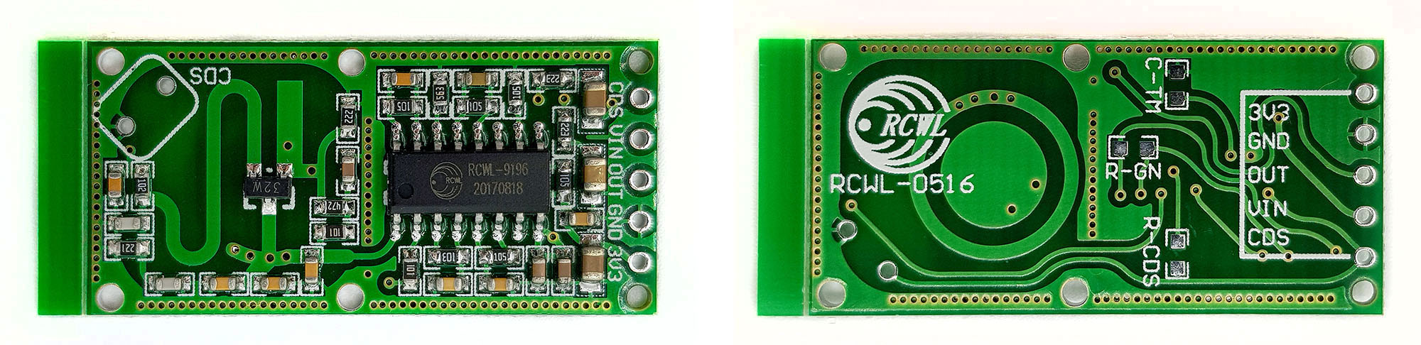
Pinout of the RCWL-0516
VIN / GND are used for power supply. OUT provides the motion signal. 3V3 – I had already explained this pin At CDS you can connect an external photo resistor (LDR) to deactivate the OUT pin in daylight. Details will follow. You can also use the pin to disable the OUT pin without LDR by connecting it to GND. However, the module is still active, so you don’t get any advantage in terms of its power consumption.
What does CDS stand for?
CDS stands for cadmium sulfide and this is the photo active substance in most LDRs. Sometimes LDRs are called CDS photo resistors for this reason.
RCWL-0516 settings
If you take a closer look at the module, you will see three (pinless) jumpers on the back and a connector for an LDR (CDS) on the front. On the RCWL-0516, three settings can be made by equipping these jumpers with resistors and capacitors:
- CDS / R-CDS: by connecting an LDR to CDS and a suitable resistor to R-CDS, the OUT output can be deactivated in daylight
- As an alternative to soldering an LDR, it can also be connected to the CDS pin. The other side of the LDR is connected to GND.
- R-GN: by connecting a suitable resistor, the range can be reduced
- C-TM: the signal length can be varied by connecting a suitable capacitor.
As already mentioned, there is little to find about how to choose these parameters. For this reason, I tried a bit and soldered cables to the jumpers:

This allowed me to play around on the breadboard:

The corresponding circuit on the Arduino looks like this (I saved the jumper connections in the scheme):
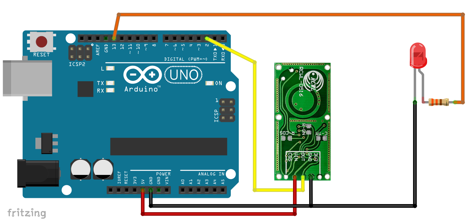
And here is the corresponding simple sketch:
int ledPin = 13;

void setup() {

  pinMode(outPin, INPUT);
  pinMode(ledPin, OUTPUT);

}

void loop() {
  while(digitalRead(outPin)==1){
    digitalWrite(ledPin, HIGH);
  }
  digitalWrite(ledPin, LOW);

}
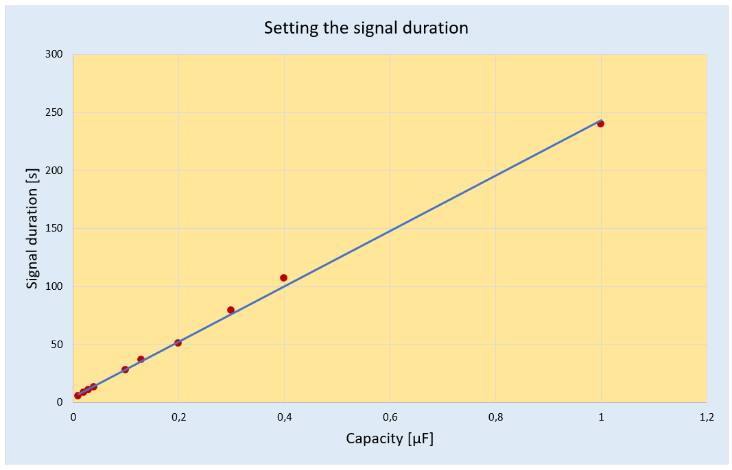
signal length setting
In data sheets and product information you will find the following information for setting the signal length:

Not exactly helpful – or can anyone explain to me what that means in terms of the capacitor details to be chosen? I therefore connected a number of capacitors to C-TM and then measured the signal length (see below). It turned out that the relation between capacity and signal length is reasonably linear. I don’t know the maximum capacity because I just didn’t want to wait longer than 240 s (at 1 µF).
Setting the daylight shutdown
If you use the motion sensor to turn on a lamp, then it makes perfect sense to disable this function in daylight. As already mentioned, you either solder an LDR to the CDS connector on the module or you attach an LDR to the CDS pin. But that alone is not enough because this way your OUT deactivates even in the dark. You must also attach a resistor to R-CDS. The size of this resistor determines at which brightness the OUT signal becomes active again.
To capture this quantitatively, I connected various resistors to R-CDS and a potentiometer to CDS. Then I tested at which limit resistor value OUT became active or inactive. Here, too, it was a linear relation. The OUT pin becomes active (or inactive) when the LDR has a resistor value that is at about one third of the resistor at R-CDS.

Range setting
To adjust the range, one finds the hint that a 1 MOhm resistor at R-GN lowers the range to 5 meters. I have tested this and various other resistances in terms of their effect on range. In contrast to the other settings, I can only provide rough guide values here, as the range cannot be measured exactly. And it should be noted that I could not verify the 7-meter range anyway. So, here are my results:
- without resistor: approx. 6 meters
- R-GN = 1 M: approx. 4.5 meters
- R-GN = 470 k: approx. 2.5 meters
- R-GN = 270 k: approx. 1.5 meters
- R-GN = 100 k: 0 meters (no movement is detected)
RCWL-0516 vs PIR HC-SR501
Thanks to its adjustment options, the RCWL-0516 can in principle be used in the same way as the more widely used PIR HC-SR501. For both, you don’t need a microcontroller for the classic application “Turn on the light when you detect motion”. One relay or transistor is sufficient.
The disadvantage of the RCWL-0516 is of course that you have to solder resistors and capacitors to change the settings. One advantage, however, is its integrated daylight shutdown.
The maximum range of the PIR is slightly wider than that of the RCWL-0516. Within the range of coverage, however, the RCWL-0516 seems to me to be much more sensitive – which does not necessarily have to be an advantage. The PIR reacts somewhat more specifically to living beings, whereas the RCWL-0516 reacts to e.g. to movements of plants in the wind.
One advantage of the RCWL-0516 is that its microwave radiation can penetrate many materials (rule: anything that doesn’t get hot in the microwave) and you can hide or protect it better than the PIR.
Bad modules with low range
Some readers have purchased modules that have a range of only a few centimeters. Two readers have sent me their modules. All capacitors and resistors seem to be OK. The only relevant difference is the date on the chip. Both non-functioning modules have the date 20211220. Do you also have problem modules? Then please leave a comment and tell us the date on your module.
Addendum: apparently not all modules have a date on the chip. I have also successfully tested some with the label “BISS0001 / A191138.1”.
Acknowledgement
For the post picture I used pictures of Pixabay again:
- The microwave oven comes from Clker-Free-Vector-Images
- I owe the small radar bowl to OpenClipart-Vectors
Last week I received some RCWL-0516 modules and each one seemed to have this low sensitivity problem. Time stamps on the RCWL-9196 IC’s are 20250619. After some research I found the schematics of this module that helped me find the cause of the problem. I had some old ones which performed well, so I compared them with the weak modules. They seemed to be totally identical but in the case of capacitors one can’t tell the exact values. In the microwave oscillator there are two 33pF capacitors that could be critical. So I desoldered them and one happened to be 68pF, the other 100pF, I replaced them with 33pF capacitors and the modules became functional like the old ones. These two capacitors are the ones that are in parallel with the 220 ohm emitter resistance in the oscillator circuit. I hope this will help others with the same problem.
Hi Peter, thanks for sharing this. Indeed, this may help many people.
For users who are not sure where to find these capacitors. It is C12 and C14 on this scheme:
https://cdn.sparkfun.com/assets/b/3/2/b/6/RCWL-0516_Schematic.pdf
I have a number of these that have very short range as well. I’ve examined the boards closely for any indication of the date, but do not see it.
Where on the boards are you seeing ‘20211220’ or ‘20201105’?
Thanks!
The label is on the IC below “RCWL-0516”- if it has a label at all. It’s really annoying that there is so much rubbish out there!
Yes, I agree. Well, it looks like my boards do not have the label. I have purchased ten all together (two separate orders of five) and one of them works amazingly well, the rest are all junk.
https://imgur.com/a/edb4w4W
Can we detect range and angle with this sensor? Please give tech details. Also I want to see its analogue waveforms in Matlab / simulink but its not available in library….help.
I don’t know how an angele could be detected.
Regading the other question: there is no good documentation (a datasheet which you could really call a datatsheet) of the RCWL-0516 available as it seems. This module is a bit of a black box. The best information I have found is:
https://www.makerhero.com/img/files/download/RCWL0516-Datasheet.pdf
Hope this helps a bit.
Sir, all 2021 series modules are non functioning
Thank you! This is really annoying and there is nothing you can do about it except sending the modules back to the seller. Can you share the dates that are printed on the IC?
I have five “20211220” labeled modules and they all show this short range 1 cm, but
if you operate 2 at the same time then they operate at 5-6 meter. Both triggering.
So this is for me not a complete loss.
That’s interesting! Thank you for sharing that experience. I am struggling to explain that behaviour to be honest. But great, this workaround might help many people who have these faulty modules!
I was also same test and result , also mater where you plase this sensor , like i banch test working parfect , but when instal in bathroom not any rsponce ( my thort and figar out much range not working in small area)
I also conducted the same test and obtained similar results. also matter where you place this sensor, like bench test, it works perfectly. However, when installed in the toilet (3.50 feet x 3.50 feet), there is no response. My thought is that the long range might not working for small area
Ignore my first post,
I also conducted the same test and obtained similar results. also matter where you place this sensor, like bench test, it works perfectly. However, when installed in the toilet (3.50 feet x 3.50 feet), there is no response. My thought is that the long range might not working for small area
5 Modules printed 20201105 on IC are non functioning.
They does functioning different distance between 2-3 centimeters and 1-2 meters according to place. But most place it does short range.
Thanks for the info. It’s really a shame that these non-working modules are so wide spread. First time I hear that also module from 2020 do not work. For information: I have some with a label 20220520 and 20170818 which work.
Hallo Wolfgang,
kannst du mir einen Schaltplan geben, wie ich einen Transistor ansteuern kann.
, bei 5 Volt Eingangsspannung.
vielen Dank
Ulrich
Good article, thank you for sharing. I find the RCWL-0516 to be very sensitive and I like the fact that I can hide it in an enclosure. I do think it will not be ideal for battery operation as it has a higher power consumption. I find that it is very picky about supply voltage – it won’t run from the 5V output of my ESP32, but works fine if I run it from a lithium battery
The 5V output is connected to the USB connector. So, maximum current is limited by the USB power supply. PCs usually provide up to 500 mA, which should be sufficient for the esp32 and the module. Maybe a capacitor helps?