About this post
- Measuring angles
- Interrupts
- Low-Power / Cycle Mode
- FIFO Buffer
The MPU9250 connected to an Arduino UNO
I used the wiring shown below for the example sketches:

Introduction to the Library MPU9250_WE – Part 2
Angles
You can use the (earth) acceleration data to calculate tilt angles. You need to make sure that no additional acceleration is applied to the MPU9250. I have implemented two methods for this.
Example sketch 6: MPU9250_angles_and_orientation
In this sketch, I simply calculate the angles between the axes and the horizontal from the arc sine of the acceleration value.
![\[ \alpha=\arcsin(\text{gValue}) \]](https://wolles-elektronikkiste.de/wp-content/ql-cache/quicklatex.com-5a67c600148498a81b63d455f4490e50_l3.png "Rendered by QuickLaTeX.com")
For small angles this works perfectly, at larger angles the error increases. Why this is the case, I explained in my article about the MMA7361. Up to 60° the deviation in my experiments was less than one degree.
For this sketch, I recommend the autoOffset() method. With this function, you start at an angle of 0° for the x- and y-axis. For the z-axis you start at 90°. However, you will only get reasonable values for the tilt angles if you position the MPU9250 flat in its x,y-plane for calibration.
Here’s the sketch.
#include <MPU9250_WE.h>
#include <Wire.h>
#define MPU9250_ADDR 0x68

/* There are several ways to create your MPU9250 object:
 * MPU9250_WE myMPU9250 = MPU9250_WE()              -> uses Wire / I2C Address = 0x68
 * MPU9250_WE myMPU9250 = MPU9250_WE(MPU9250_ADDR)  -> uses Wire / MPU9250_ADDR
 * MPU9250_WE myMPU9250 = MPU9250_WE(&wire2)        -> uses the TwoWire object wire2 / MPU9250_ADDR
 * MPU9250_WE myMPU9250 = MPU9250_WE(&wire2, MPU9250_ADDR) -> all together
 * Successfully tested with two I2C busses on an ESP32
 */
MPU9250_WE myMPU9250 = MPU9250_WE(MPU9250_ADDR);

void setup() {
  Serial.begin(115200);
  Wire.begin();
  if(!myMPU9250.init()){
    Serial.println("MPU9250 does not respond");
  }
  else{
    Serial.println("MPU9250 is connected");
  }

  /* The slope of the curve of acceleration vs measured values fits quite well to the theoretical
   * values, e.g. 16384 units/g in the +/- 2g range. But the starting point, if you position the
   * MPU9250 flat, is not necessarily 0g/0g/1g for x/y/z. The autoOffset function measures offset
   * values. It assumes your MPU9250 is positioned flat with its x,y-plane. The more you deviate
   * from this, the less accurate will be your results.
   * The function also measures the offset of the gyroscope data. The gyroscope offset does not
   * depend on the positioning.
   * This function needs to be called at the beginning since it can overwrite your settings!
   */
  Serial.println("Position you MPU9250 flat and don't move it - calibrating...");
  delay(1000);
  myMPU9250.autoOffsets();
  Serial.println("Done!");

  /*  This is a more accurate method for calibration. You have to determine the minimum and maximum
   *  raw acceleration values of the axes determined in the range +/- 2 g.
   *  You call the function as follows: setAccOffsets(xMin,xMax,yMin,yMax,zMin,zMax);
   *  Use either autoOffset or setAccOffsets, not both.
   */
  //myMPU9250.setAccOffsets(-14240.0, 18220.0, -17280.0, 15590.0, -20930.0, 12080.0);

  /*  Sample rate divider divides the output rate of the gyroscope and accelerometer.
   *  Sample rate = Internal sample rate / (1 + divider)
   *  It can only be applied if the corresponding DLPF is enabled and 0<DLPF<7!
   *  Divider is a number 0...255
   */
  //myMPU9250.setSampleRateDivider(5);

  /*  MPU9250_ACC_RANGE_2G      2 g
   *  MPU9250_ACC_RANGE_4G      4 g
   *  MPU9250_ACC_RANGE_8G      8 g
   *  MPU9250_ACC_RANGE_16G    16 g
   */
  myMPU9250.setAccRange(MPU9250_ACC_RANGE_2G);

  /*  Enable/disable the digital low pass filter for the accelerometer
   *  If disabled the bandwidth is 1.13 kHz, delay is 0.75 ms, output rate is 4 kHz
   */
  myMPU9250.enableAccDLPF(true);

 /*  Digital low pass filter (DLPF) for the accelerometer (if DLPF enabled)
   *  MPU9250_DPLF_0, MPU9250_DPLF_2, ...... MPU9250_DPLF_7
   *   DLPF     Bandwidth [Hz]      Delay [ms]    Output rate [kHz]
   *     0           460               1.94           1
   *     1           184               5.80           1
   *     2            92               7.80           1
   *     3            41              11.80           1
   *     4            20              19.80           1
   *     5            10              35.70           1
   *     6             5              66.96           1
   *     7           460               1.94           1
   */
  myMPU9250.setAccDLPF(MPU9250_DLPF_6);
}

void loop() {
  xyzFloat gValue = myMPU9250.getGValues();
  xyzFloat angle = myMPU9250.getAngles();

/* For g-values the corrected raws are used */
  Serial.print("g-x      = ");
  Serial.print(gValue.x);
  Serial.print("  |  g-y      = ");
  Serial.print(gValue.y);
  Serial.print("  |  g-z      = ");
  Serial.println(gValue.z);

/* Angles are also based on the corrected raws. Angles are simply calculated by
   angle = arcsin(g Value) */
  Serial.print("Angle x  = ");
  Serial.print(angle.x);
  Serial.print("  |  Angle y  = ");
  Serial.print(angle.y);
  Serial.print("  |  Angle z  = ");
  Serial.println(angle.z);

  Serial.print("Orientation of the module: ");
  Serial.println(myMPU9250.getOrientationAsString());

  Serial.println();

  delay(1000);
}
I have explained almost all the functions used here in part 1 of the article. These are the new functions:
getAngle()returns the angle of the x, y, and z axes to the horizontal in degrees.- g-values above 1 are truncated to 1 because the arc sine function is not defined for larger values.
getOrientationAsString()indicates which axis has the largest positive angle.- Possible return values are: x up, x down, y up, y down, z up, z down.
- An alternative is
getOrientation(). The return value is an enum (MPU9250_orientation). For the definition, look at MPU9250_WE.h.
Output of MPU9250_angles_and_orientation.ino
For the following output I have rotated the module around the y-axis, i.e. I have erected the x-axis.

The sum of the angles of x and z should always be 90° in this process. However, this is obviously not the case. As already mentioned, the large angles are not exact.
Example sketch 7: MPU9250_pitch_and_roll.ino
This method uses multiple axes to calculate the angles. As a result, the values are more accurate at large angles than with the simple arc-sine method. On the other hand, at small angles, the latter method is preferable. To delineate the method, I used the nomenclature of other libraries and referred to the x-axis tilt angle as “pitch” and the y-axis tilt angle as “roll angle”. You find a definition here, for example.
![\[ pitch\; angle= \arctan \left(\frac{-g_x}{\sqrt{g_y^2 +g_z^2}}\right) \]](https://wolles-elektronikkiste.de/wp-content/ql-cache/quicklatex.com-93a10b5618bd510697d13a24839131a6_l3.png "Rendered by QuickLaTeX.com")
![\[ roll\;angle = \arctan\left( \frac{g_y}{g_z} \right) \]](https://wolles-elektronikkiste.de/wp-content/ql-cache/quicklatex.com-57b6353d86e08703d0092d687a18be3d_l3.png "Rendered by QuickLaTeX.com")
For comparison, I use both methods in this sketch. Try it out and choose what suits you more.
#include <MPU9250_WE.h>
#include <Wire.h>
#define MPU9250_ADDR 0x68

/* There are several ways to create your MPU9250 object:
 * MPU9250_WE myMPU9250 = MPU9250_WE()              -> uses Wire / I2C Address = 0x68
 * MPU9250_WE myMPU9250 = MPU9250_WE(MPU9250_ADDR)  -> uses Wire / MPU9250_ADDR
 * MPU9250_WE myMPU9250 = MPU9250_WE(&wire2)        -> uses the TwoWire object wire2 / MPU9250_ADDR
 * MPU9250_WE myMPU9250 = MPU9250_WE(&wire2, MPU9250_ADDR) -> all together
 * Successfully tested with two I2C busses on an ESP32
 */
MPU9250_WE myMPU9250 = MPU9250_WE(MPU9250_ADDR);

void setup() {
  Serial.begin(115200);
  Wire.begin();
  if(!myMPU9250.init()){
    Serial.println("MPU9250 does not respond");
  }
  else{
    Serial.println("MPU9250 is connected");
  }

  /* The slope of the curve of acceleration vs measured values fits quite well to the theoretical
   * values, e.g. 16384 units/g in the +/- 2g range. But the starting point, if you position the
   * MPU9250 flat, is not necessarily 0g/0g/1g for x/y/z. The autoOffset function measures offset
   * values. It assumes your MPU9250 is positioned flat with its x,y-plane. The more you deviate
   * from this, the less accurate will be your results.
   * The function also measures the offset of the gyroscope data. The gyroscope offset does not
   * depend on the positioning.
   * This function needs to be called at the beginning since it can overwrite your settings!
   */
  Serial.println("Position you MPU9250 flat and don't move it - calibrating...");
  delay(1000);
  myMPU9250.autoOffsets();
  Serial.println("Done!");

  /*  This is a more accurate method for calibration. You have to determine the minimum and maximum
   *  raw acceleration values of the axes determined in the range +/- 2 g.
   *  You call the function as follows: setAccOffsets(xMin,xMax,yMin,yMax,zMin,zMax);
   *  Use either autoOffset or setAccOffsets, not both.
   */
  //myMPU9250.setAccOffsets(-14240.0, 18220.0, -17280.0, 15590.0, -20930.0, 12080.0);

  /*  Sample rate divider divides the output rate of the gyroscope and accelerometer.
   *  Sample rate = Internal sample rate / (1 + divider)
   *  It can only be applied if the corresponding DLPF is enabled and 0<DLPF<7!
   *  Divider is a number 0...255
   */
  myMPU9250.setSampleRateDivider(5);

  /*  MPU9250_ACC_RANGE_2G      2 g    (default)
   *  MPU9250_ACC_RANGE_4G      4 g
   *  MPU9250_ACC_RANGE_8G      8 g
   *  MPU9250_ACC_RANGE_16G    16 g
   */
  myMPU9250.setAccRange(MPU9250_ACC_RANGE_2G);

  /*  Enable/disable the digital low pass filter for the accelerometer
   *  If disabled the bandwidth is 1.13 kHz, delay is 0.75 ms, output rate is 4 kHz
   */
  myMPU9250.enableAccDLPF(true);


  /*  Digital low pass filter (DLPF) for the accelerometer, if enabled
   *  MPU9250_DPLF_0, MPU9250_DPLF_2, ...... MPU9250_DPLF_7
   *   DLPF     Bandwidth [Hz]      Delay [ms]    Output rate [kHz]
   *     0           460               1.94           1
   *     1           184               5.80           1
   *     2            92               7.80           1
   *     3            41              11.80           1
   *     4            20              19.80           1
   *     5            10              35.70           1
   *     6             5              66.96           1
   *     7           460               1.94           1
   */
  myMPU9250.setAccDLPF(MPU9250_DLPF_6);
}

void loop() {
  xyzFloat angles = myMPU9250.getAngles();

/* This method provides quite precise values for x/y
   angles up 60°. */
  Serial.print("Angle x = ");
  Serial.print(angles.x);
  Serial.print("  |  Angle y = ");
  Serial.print(angles.y);
  Serial.print("  |  Angle z = ");
  Serial.println(angles.z);

/* Pitch and roll consider all axes for calculation. According to my experience
   it provides more reliable results at higher angles (>60°) */
  float pitch = myMPU9250.getPitch();
  float roll  = myMPU9250.getRoll();

  Serial.print("Pitch   = ");
  Serial.print(pitch);
  Serial.print("  |  Roll    = ");
  Serial.println(roll);

  Serial.println();

  delay(1000);
}
Two new functions are used here:
getPitch()returns the pitch angle (x-axis).getRoll()returns the roll angle (y-axis).
Use of interrupts of the MPU9250
The MPU9250 has the following interrupts:
- Wake on Motion (“WOM”): is triggered when an acceleration value threshold is exceeded.
- Data Ready: is triggered when new measured values are available.
- FIFO Overflow: is triggered when the FIFO memory is full (512 bytes).
- FSYNC: an interrupt is triggered when a HIGH or LOW is attached to FSYNC (but I have not implemented this feature).
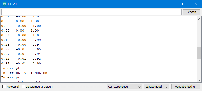
Example sketch 8: MPU9250_wake_on_motion_interrupt.ino
The name “Wake on Motion” suggests that the MPU9250 could wake up from sleep mode using this interrupt. However, this is not the case. It is a simple acceleration interrupt.
#include <MPU9250_WE.h>
#include <Wire.h>
#define MPU9250_ADDR 0x68

const int intPin = 2;
volatile bool motion = false;

/* There are several ways to create your MPU9250 object:
 * MPU9250_WE myMPU9250 = MPU9250_WE()              -> uses Wire / I2C Address = 0x68
 * MPU9250_WE myMPU9250 = MPU9250_WE(MPU9250_ADDR)  -> uses Wire / MPU9250_ADDR
 * MPU9250_WE myMPU9250 = MPU9250_WE(&wire2)        -> uses the TwoWire object wire2 / MPU9250_ADDR
 * MPU9250_WE myMPU9250 = MPU9250_WE(&wire2, MPU9250_ADDR) -> all together
 * Successfully tested with two I2C busses on an ESP32
 */
MPU9250_WE myMPU9250 = MPU9250_WE(MPU9250_ADDR);


void setup() {
  Serial.begin(115200);
  Wire.begin();
  if(!myMPU9250.init()){
    Serial.println("MPU9250 does not respond");
  }
  else{
    Serial.println("MPU9250 is connected");
  }

 /* The slope of the curve of acceleration vs measured values fits quite well to the theoretical
   * values, e.g. 16384 units/g in the +/- 2g range. But the starting point, if you position the
   * MPU9250 flat, is not necessarily 0g/0g/1g for x/y/z. The autoOffset function measures offset
   * values. It assumes your MPU9250 is positioned flat with its x,y-plane. The more you deviate
   * from this, the less accurate will be your results.
   * The function also measures the offset of the gyroscope data. The gyroscope offset does not
   * depend on the positioning.
   * This function needs to be called at the beginning since it can overwrite your settings!
   */
  Serial.println("Position you MPU9250 flat and don't move it - calibrating...");
  delay(1000);
  myMPU9250.autoOffsets();
  Serial.println("Done!");

  /*  This is a more accurate method for calibration. You have to determine the minimum and maximum
   *  raw acceleration values of the axes determined in the range +/- 2 g.
   *  You call the function as follows: setAccOffsets(xMin,xMax,yMin,yMax,zMin,zMax);
   *  Use either autoOffset or setAccOffsets, not both.
   */
  //myMPU9250.setAccOffsets(-14240.0, 18220.0, -17280.0, 15590.0, -20930.0, 12080.0);

  /*  Sample rate divider divides the output rate of the gyroscope and accelerometer.
   *  Sample rate = Internal sample rate / (1 + divider)
   *  It can only be applied if the corresponding DLPF is enabled and 0<DLPF<7!
   *  Divider is a number 0...255
   */
  myMPU9250.setSampleRateDivider(5);

  /*  MPU9250_ACC_RANGE_2G      2 g   (default)
   *  MPU9250_ACC_RANGE_4G      4 g
   *  MPU9250_ACC_RANGE_8G      8 g
   *  MPU9250_ACC_RANGE_16G    16 g
   */
  myMPU9250.setAccRange(MPU9250_ACC_RANGE_2G);


  /*  Enable/disable the digital low pass filter for the accelerometer
   *  If disabled the the bandwidth is 1.13 kHz, delay is 0.75 ms, output rate is 4 kHz
   */
  myMPU9250.enableAccDLPF(true);

  /*  Digital low pass filter (DLPF) for the accelerometer, if enabled
   *  MPU9250_DPLF_0, MPU9250_DPLF_2, ...... MPU9250_DPLF_7
   *   DLPF     Bandwidth [Hz]      Delay [ms]    Output rate [kHz]
   *     0           460               1.94           1
   *     1           184               5.80           1
   *     2            92               7.80           1
   *     3            41              11.80           1
   *     4            20              19.80           1
   *     5            10              35.70           1
   *     6             5              66.96           1
   *     7           460               1.94           1
   */
  myMPU9250.setAccDLPF(MPU9250_DLPF_6);

  /*  Set Accelerometer Output Data Rate in Low Power Mode
   *   MPU9250_LP_ACC_ODR_0_24      0.24 Hz
   *   MPU9250_LP_ACC_ODR_0_49      0.49 Hz
   *   MPU9250_LP_ACC_ODR_0_98      0.98 Hz
   *   MPU9250_LP_ACC_ODR_1_95      1.95 Hz
   *   MPU9250_LP_ACC_ODR_3_91      3.91 Hz
   *   MPU9250_LP_ACC_ODR_7_81      7.81 Hz
   *   MPU9250_LP_ACC_ODR_15_63    15.63 Hz
   *   MPU9250_LP_ACC_ODR_31_25    31.25 Hz
   *   MPU9250_LP_ACC_ODR_62_5     62.5 Hz
   *   MPU9250_LP_ACC_ODR_125     125 Hz
   *   MPU9250_LP_ACC_ODR_250     250 Hz
   *   MPU9250_LP_ACC_ODR_500     500 Hz
   */
  //myMPU9250.setLowPowerAccDataRate(MPU9250_LP_ACC_ODR_125);

   /*  Set the interrupt pin:
   *  MPU9250_ACT_LOW  = active-low
   *  MPU9250_ACT_HIGH = active-high (default)
   */
  myMPU9250.setIntPinPolarity(MPU9250_ACT_HIGH);

  /*  If latch is enabled the interrupt pin level is held until the interrupt status
   *  is cleared. If latch is disabled the interrupt pulse is ~50µs (default).
   */
  myMPU9250.enableIntLatch(true);

   /*  The interrupt can be cleared by any read or it will only be cleared if the interrupt
   *  status register is read (default).
   */
  myMPU9250.enableClearIntByAnyRead(false);

  /*  Enable/disable interrupts:
   *  MPU9250_DATA_READY
   *  MPU9250_FIFO_OVF
   *  MPU9250_WOM_INT
   *
   *  You can enable all interrupts.
   */
  myMPU9250.enableInterrupt(MPU9250_WOM_INT);
  //myMPU9250.disableInterrupt(MPU9250_FIFO_OVF);

  /*  Set the Wake On Motion Threshold
   *  Choose 1 (= 4 mg) ..... 255 (= 1020 mg);
   */
  myMPU9250.setWakeOnMotionThreshold(128);  // 128 = ~0.5 g

   /*  Enable/disable wake on motion (WOM) and  WOM mode:
   *  MPU9250_WOM_DISABLE
   *  MPU9250_WOM_ENABLE
   *  ***
   *  MPU9250_WOM_COMP_DISABLE   // reference is the starting value
   *  MPU9250_WOM_COMP_ENABLE    // reference is the last value
   */
  myMPU9250.enableWakeOnMotion(MPU9250_WOM_ENABLE, MPU9250_WOM_COMP_DISABLE);

  /* You can enable or disable the axes for gyroscope and/or accelerometer measurements.
   * By default all axes are enabled. Parameters are:
   * MPU9250_ENABLE_XYZ  //all axes are enabled (default)
   * MPU9250_ENABLE_XY0  // X, Y enabled, Z disabled
   * MPU9250_ENABLE_X0Z
   * MPU9250_ENABLE_X00
   * MPU9250_ENABLE_0YZ
   * MPU9250_ENABLE_0Y0
   * MPU9250_ENABLE_00Z
   * MPU9250_ENABLE_000  // all axes disabled
   */
  //myMPU9250.enableAccAxes(MPU9250_ENABLE_XYZ);
  attachInterrupt(digitalPinToInterrupt(intPin), motionISR, RISING);
  Serial.println("Turn your MPU9250 and see what happens...");

}

void loop() {
  xyzFloat gValue;

  if((millis()%1000) == 0){
    gValue = myMPU9250.getGValues();

    Serial.print(gValue.x);
    Serial.print("   ");
    Serial.print(gValue.y);
    Serial.print("   ");
    Serial.println(gValue.z);
  }
  if(motion){
    byte source = myMPU9250.readAndClearInterrupts();
    Serial.println("Interrupt!");
    if(myMPU9250.checkInterrupt(source, MPU9250_WOM_INT)){
      Serial.println("Interrupt Type: Motion");
      delay(1000);
    }
    motion = false;
    // if additional interrupts have occured in the meantime:
    myMPU9250.readAndClearInterrupts();
  }

}

void motionISR() {
  motion = true;
}
Here I use a number of additional functions to control the interrupts:
setIntPinPolarity()sets whether the interrupt pin is active-high or active-low.enableLatch()controls whether the interrupt is output as a short signal at the interrupt pin, or whether the signal remains permanently at interrupt level until the interrupt is cleared (latch = locking).- With
enableClearIntByAnyRead(), you set whether the interrupt is cleared with any read operation or only by reading the interrupt status register. The function only makes sense in combination withenableLatch(). - With
enableInterrupt()you choose which interrupt type you want to activate. If you want to enable multiple interrupts, then call function multiple times. disableInterrupt()deactivates an interrupt.setWakeOnMotionThreshold(value)determines at which acceleration an interrupt is triggered. “value” is the difference to a comparative value and can be selected between 1 (= 4 mg) and 255 (1.02 g). The interrupt is not axis-specific. If you want to exclude certain axes, you need to disable them.enableWakeOnMotion()expects two arguments. Argument 1 enables the interrupt or pauses it. With the second argument, you determine the comparative value mentioned above. This is either the initial value when activating the interrupt or the last reading.readAndClearInterrupts()reads the interrupt status register and clears the active interrupt (if “latch” is enabled). The function returns the contents of the status register.checkInterrupt()can be used to check if a particular interrupt has been triggered. You can also directly evaluate the return value ofreadAndClearInterrupt(). However, you have to look at MPU9250_WE.h to see how it is defined.
Output of MPU9250_wake_on_motion_interrupt.ino
By slowly erecting the x-axis of the MPU9250, I got the following output.
With this sketch many parameters and functions were introduced. I suggest to plays around with them to better understand the effect.
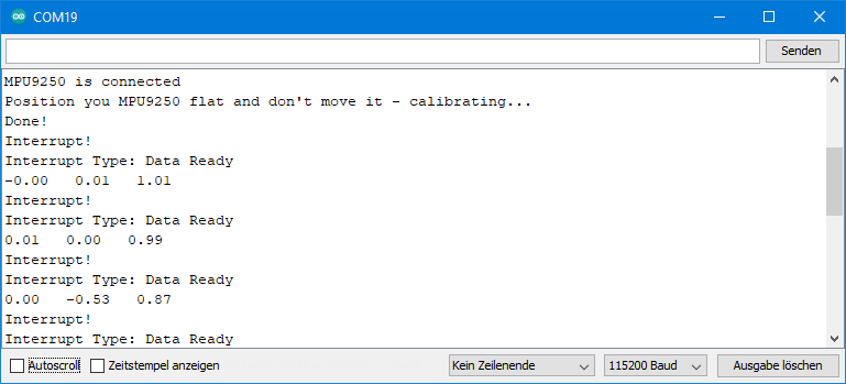
Example sketch 9: MPU9250_data_ready_interrupt_and_cycle.ino
Here I kill two birds with one stone. I explain the Data Ready Interrupt and Cycle Mode together in one sketch.
The cycle mode is a low-power mode in which the MPU9250 sleeps most of the time, saving power. At fixed intervals, it wakes up, measures an acceleration value and “falls asleep” again.
Note: The cycle mode is incompatible with the low-pass filter (DLPF). Leave it off. Accordingly, the sample rate divider is also ineffective. Likewise, you cannot record gyroscope data during wake-up phases (not least because the gyroscope takes a long 35 milliseconds to wake up).
#include <MPU9250_WE.h>
#include <Wire.h>
#define MPU9250_ADDR 0x68

const int intPin = 2;
volatile bool dataReady = false;

/* There are several ways to create your MPU9250 object:
 * MPU9250_WE myMPU9250 = MPU9250_WE()              -> uses Wire / I2C Address = 0x68
 * MPU9250_WE myMPU9250 = MPU9250_WE(MPU9250_ADDR)  -> uses Wire / MPU9250_ADDR
 * MPU9250_WE myMPU9250 = MPU9250_WE(&wire2)        -> uses the TwoWire object wire2 / MPU9250_ADDR
 * MPU9250_WE myMPU9250 = MPU9250_WE(&wire2, MPU9250_ADDR) -> all together
 * Successfully tested with two I2C busses on an ESP32
 */
MPU9250_WE myMPU9250 = MPU9250_WE(MPU9250_ADDR);

void setup() {
  Serial.begin(115200);
  Wire.begin();
  if(!myMPU9250.init()){
    Serial.println("MPU9250 does not respond");
  }
  else{
    Serial.println("MPU9250 is connected");
  }

  /* The slope of the curve of acceleration vs measured values fits quite well to the theoretical
   * values, e.g. 16384 units/g in the +/- 2g range. But the starting point, if you position the
   * MPU9250 flat, is not necessarily 0g/0g/1g for x/y/z. The autoOffset function measures offset
   * values. It assumes your MPU9250 is positioned flat with its x,y-plane. The more you deviate
   * from this, the less accurate will be your results.
   * The function also measures the offset of the gyroscope data. The gyroscope offset does not
   * depend on the positioning.
   * This function needs to be called at the beginning since it can overwrite your settings!
   */
  Serial.println("Position you MPU9250 flat and don't move it - calibrating...");
  delay(1000);
  myMPU9250.autoOffsets();
  Serial.println("Done!");

  /*  This is a more accurate method for calibration. You have to determine the minimum and maximum
   *  raw acceleration values of the axes determined in the range +/- 2 g.
   *  You call the function as follows: setAccOffsets(xMin,xMax,yMin,yMax,zMin,zMax);
   *  Use either autoOffset or setAccOffsets, not both.
   */
  //myMPU9250.setAccOffsets(-14240.0, 18220.0, -17280.0, 15590.0, -20930.0, 12080.0);

  /*  Sample rate divider divides the output rate of the gyroscope and accelerometer.
   *  Sample rate = Internal sample rate / (1 + divider)
   *  It can only be applied if the corresponding DLPF is enabled and 0<DLPF<7!
   *  Divider is a number 0...255
   */
  myMPU9250.setSampleRateDivider(5);

  /*  MPU9250_ACC_RANGE_2G      2 g   (default)
   *  MPU9250_ACC_RANGE_4G      4 g
   *  MPU9250_ACC_RANGE_8G      8 g
   *  MPU9250_ACC_RANGE_16G    16 g
   */
  myMPU9250.setAccRange(MPU9250_ACC_RANGE_2G);

  /*  Enable/disable the digital low pass filter for the accelerometer
   *  If disabled the the bandwidth is 1.13 kHz, delay is 0.75 ms, output rate is 4 kHz
   */
  myMPU9250.enableAccDLPF(false);

  /*  Set accelerometer output data rate in low power mode (cycle enabled)
   *   MPU9250_LP_ACC_ODR_0_24          0.24 Hz
   *   MPU9250_LP_ACC_ODR_0_49          0.49 Hz
   *   MPU9250_LP_ACC_ODR_0_98          0.98 Hz
   *   MPU9250_LP_ACC_ODR_1_95          1.95 Hz
   *   MPU9250_LP_ACC_ODR_3_91          3.91 Hz
   *   MPU9250_LP_ACC_ODR_7_81          7.81 Hz
   *   MPU9250_LP_ACC_ODR_15_63        15.63 Hz
   *   MPU9250_LP_ACC_ODR_31_25        31.25 Hz
   *   MPU9250_LP_ACC_ODR_62_5         62.5 Hz
   *   MPU9250_LP_ACC_ODR_125         125 Hz
   *   MPU9250_LP_ACC_ODR_250         250 Hz
   *   MPU9250_LP_ACC_ODR_500         500 Hz
   */
  myMPU9250.setLowPowerAccDataRate(MPU9250_LP_ACC_ODR_0_24);

  /*  Set the interrupt pin:
   *  MPU9250_ACT_LOW  = active-low
   *  MPU9250_ACT_HIGH = active-high (default)
   */
  myMPU9250.setIntPinPolarity(MPU9250_ACT_HIGH);

  /*  If latch is enabled the Interrupt Pin Level is held until the Interrupt Status
   *  is cleared. If latch is disabled the Interrupt Puls is ~50µs (default).
   */
  myMPU9250.enableIntLatch(true);

  /*  The Interrupt can be cleared by any read. Otherwise the Interrupt will only be
   *  cleared if the Interrupt Status register is read (default).
   */
  myMPU9250.enableClearIntByAnyRead(false);

  /*  Enable/disable interrupts:
   *  MPU9250_DATA_READY
   *  MPU9250_FIFO_OVF
   *  MPU9250_WOM_INT
   *
   *  You can enable all interrupts.
   */
  myMPU9250.enableInterrupt(MPU9250_DATA_READY);
  //myMPU9250.disableInterrupt(MPU9250_FIFO_OVF);

  /* If cycle is set, and standby or sleep are not set, the module will cycle between
   *  sleep and taking a sample at a rate determined by setLowPowerAccDataRate().
   */
  myMPU9250.enableCycle(true);

  /* You can enable or disable the axes for gyroscope and/or accelerometer measurements.
   * By default all axes are enabled. Parameters are:
   * MPU9250_ENABLE_XYZ  //all axes are enabled (default)
   * MPU9250_ENABLE_XY0  // X, Y enabled, Z disabled
   * MPU9250_ENABLE_X0Z
   * MPU9250_ENABLE_X00
   * MPU9250_ENABLE_0YZ
   * MPU9250_ENABLE_0Y0
   * MPU9250_ENABLE_00Z
   * MPU9250_ENABLE_000  // all axes disabled
   */
  //myMPU9250.enableAccAxes(MPU9250_ENABLE_XYZ);
  attachInterrupt(digitalPinToInterrupt(intPin), dataReadyISR, RISING);

}

void loop() {
  if(dataReady){
    byte source = myMPU9250.readAndClearInterrupts();
    Serial.println("Interrupt!");
    if(myMPU9250.checkInterrupt(source, MPU9250_DATA_READY)){
      Serial.println("Interrupt Type: Data Ready");
      printData();
    }
    dataReady = false;
    myMPU9250.readAndClearInterrupts(); // if additional interrupts have occured in the meantime
  }
}

void printData(){
  xyzFloat gValue;
  gValue = myMPU9250.getGValues();

  Serial.print(gValue.x);
  Serial.print("   ");
  Serial.print(gValue.y);
  Serial.print("   ");
  Serial.println(gValue.z);
}

void dataReadyISR() {
  dataReady = true;
}
The following new functions are used here:
setLowPowerAccDataRate()sets the wake-up / data rate. You can set values between 0.24 and 500 Hz.enableCycle()enables or deactivates cycle mode.
Output of MPU9250_data_ready_and_cycle.ino
As I have set the data rate to 0.24 Hz, the MPU9250 wakes up about every four seconds and takes a measurement. The Data Ready Interrupt controls the measurement recording and output rate. You see that the main loop of the sketch does not contain any delay.
Using the FIFO memory of the MPU9250
The FIFO (first in, first out) memory is a kind of recorder for measurement data. The data that the MPU9250 writes first, it also reads first – hence the name. The FIFO is 512 bytes in size. You determine which data is written to the FIFO. This also determines how many records fit into the FIFO. An acceleration or gyroscope value requires two bytes. It is the raw data which is stored. An x,y,z-triple therefore requires 6 bytes. I have implemented the following options:
- Acceleration values as triples – 85 complete data triples fit into the FIFO (512 / 6 = 85, rest 2).
- Gyroscope values as triples – 85 complete triples can be recorded.
- Acceleration and gyroscope values – 42 complete records can be written into the FIFO (512 / 12 = 42, rest 8).
Moreover, the MPU9250 can also record gyroscope data of individual axes, temperatures or data from external sensors. However, I did not implement this to keep it simple.
To read the FIFO register, the FIFO data is pushed sequentially into a single data register of one byte. From there, the bytes are read individually and “reassembled” into meaningful data. However, for the individual bytes it is not recognizable whether it is the MSB or LSB of an acceleration or a gyroscope value. So, you have to count and read the data in the right order. This can only be automated to a certain extent. And in order not to make it too complex and thus error-prone for the user, I did not implement all options.
Example sketch 10: MPU9250_FIFO_stop_when_full
In this first FIFO Sketch, the MPU9250 stops data recording when the FIFO is full. This means that you specify the start of the recording. The recording time depends on the data rate and the recorded data types. By the way, a combination with the cycle mode does not work.
When the FIFO is full, you can be informed about it by the FIFO overflow interrupt.
When recording acceleration and gyroscope data, the MPU9250 always writes the acceleration data to the FIFO first. Since it stops in this example when the FIFO is full, the FIFO data begins with an acceleration value. This is different in the next example. For proper reading this is important!
#include <MPU9250_WE.h>
#include <Wire.h>
#define MPU9250_ADDR 0x68

const int intPin = 2;
volatile bool fifoFull = false;

/* There are several ways to create your MPU9250 object:
 * MPU9250_WE myMPU9250 = MPU9250_WE()              -> uses Wire / I2C Address = 0x68
 * MPU9250_WE myMPU9250 = MPU9250_WE(MPU9250_ADDR)  -> uses Wire / MPU9250_ADDR
 * MPU9250_WE myMPU9250 = MPU9250_WE(&wire2)        -> uses the TwoWire object wire2 / MPU9250_ADDR
 * MPU9250_WE myMPU9250 = MPU9250_WE(&wire2, MPU9250_ADDR) -> all together
 * Successfully tested with two I2C busses on an ESP32
 */
MPU9250_WE myMPU9250 = MPU9250_WE(MPU9250_ADDR);

void setup() {
  Serial.begin(115200);
  Wire.begin();
  if(!myMPU9250.init()){
    Serial.println("MPU9250 does not respond");
  }
  else{
    Serial.println("MPU9250 is connected");
  }

  /* The slope of the curve of acceleration vs measured values fits quite well to the theoretical
   * values, e.g. 16384 units/g in the +/- 2g range. But the starting point, if you position the
   * MPU9250 flat, is not necessarily 0g/0g/1g for x/y/z. The autoOffset function measures offset
   * values. It assumes your MPU9250 is positioned flat with its x,y-plane. The more you deviate
   * from this, the less accurate will be your results.
   * The function also measures the offset of the gyroscope data. The gyroscope offset does not
   * depend on the positioning.
   * This function needs to be called at the beginning since it can overwrite your settings!
   */
  Serial.println("Position you MPU9250 flat and don't move it - calibrating...");
  delay(1000);
  myMPU9250.autoOffsets();
  Serial.println("Done!");

  /*  This is a more accurate method for calibration. You have to determine the minimum and maximum
   *  raw acceleration values of the axes determined in the range +/- 2 g.
   *  You call the function as follows: setAccOffsets(xMin,xMax,yMin,yMax,zMin,zMax);
   *  Use either autoOffset or setAccOffsets, not both.
   */
  //myMPU9250.setAccOffsets(-14240.0, 18220.0, -17280.0, 15590.0, -20930.0, 12080.0);

  /*  The gyroscope data is not zero, even if you don't move the MPU9250.
   *  To start at zero, you can apply offset values. These are the gyroscope raw values you obtain
   *  using the +/- 250 degrees/s range.
   *  Use either autoOffset or setGyrOffsets, not both.
   */
  //myMPU9250.setGyrOffsets(45.0, 145.0, -105.0);

  /*  You can enable or disable the digital low pass filter (DLPF). If you disable the DLPF, you
   *  need to select the bandwidth, which can be either 8800 or 3600 Hz. 8800 Hz has a shorter delay,
   *  but higher noise level. If DLPF is disabled, the output rate is 32 kHz.
   *  MPU9250_BW_WO_DLPF_3600
   *  MPU9250_BW_WO_DLPF_8800
   */
  myMPU9250.enableGyrDLPF();
  //myMPU9250.disableGyrDLPF(MPU9250_BW_WO_DLPF_8800); // bandwidth without DLPF

  /*  Digital Low Pass Filter for the gyroscope must be enabled to choose the level.
   *  MPU9250_DPLF_0, MPU9250_DPLF_2, ...... MPU9250_DPLF_7
   *
   *  DLPF    Bandwidth [Hz]   Delay [ms]   Output Rate [kHz]
   *    0         250            0.97             8
   *    1         184            2.9              1
   *    2          92            3.9              1
   *    3          41            5.9              1
   *    4          20            9.9              1
   *    5          10           17.85             1
   *    6           5           33.48             1
   *    7        3600            0.17             8
   *
   *    You achieve lowest noise using level 6
   */
  myMPU9250.setGyrDLPF(MPU9250_DLPF_5);

  /*  Sample rate divider divides the output rate of the gyroscope and accelerometer.
   *  Sample rate = Internal sample rate / (1 + divider)
   *  It can only be applied if the corresponding DLPF is enabled and 0<DLPF<7!
   *  Divider is a number 0...255
   */
  myMPU9250.setSampleRateDivider(99);

  /*  MPU9250_GYRO_RANGE_250       250 degrees per second (default)
   *  MPU9250_GYRO_RANGE_500       500 degrees per second
   *  MPU9250_GYRO_RANGE_1000     1000 degrees per second
   *  MPU9250_GYRO_RANGE_2000     2000 degrees per second
   */
  myMPU9250.setGyrRange(MPU9250_GYRO_RANGE_250);

  /*  MPU9250_ACC_RANGE_2G      2 g   (default)
   *  MPU9250_ACC_RANGE_4G      4 g
   *  MPU9250_ACC_RANGE_8G      8 g
   *  MPU9250_ACC_RANGE_16G    16 g
   */
  myMPU9250.setAccRange(MPU9250_ACC_RANGE_2G);

  /*  Enable/disable the digital low pass filter for the accelerometer
   *  If disabled the bandwidth is 1.13 kHz, delay is 0.75 ms, output rate is 4 kHz
   */
  myMPU9250.enableAccDLPF(true);

  /*  Digital low pass filter (DLPF) for the accelerometer, if enabled
   *  MPU9250_DPLF_0, MPU9250_DPLF_2, ...... MPU9250_DPLF_7
   *   DLPF     Bandwidth [Hz]      Delay [ms]    Output rate [kHz]
   *     0           460               1.94           1
   *     1           184               5.80           1
   *     2            92               7.80           1
   *     3            41              11.80           1
   *     4            20              19.80           1
   *     5            10              35.70           1
   *     6             5              66.96           1
   *     7           460               1.94           1
   */
  myMPU9250.setAccDLPF(MPU9250_DLPF_0);

  /*  Set the interrupt pin:
   *  MPU9250_ACT_LOW  = active-low
   *  MPU9250_ACT_HIGH = active-high (default)
   */
  //myMPU9250.setIntPinPolarity(MPU9250_ACT_LOW);

  /*  If latch is enabled the interrupt pin level is held until the interrupt status
   *  is cleared. If latch is disabled the interrupt pulse is ~50µs (default).
   */
  myMPU9250.enableIntLatch(true);

  /*  The interrupt can be cleared by any read or it will only be cleared if the interrupt
   *  status register is read (default).
   */
  //myMPU9250.enableClearIntByAnyRead(true);

  /*  Enable/disable interrupts:
   *  MPU9250_DATA_READY
   *  MPU9250_FIFO_OVF
   *  MPU9250_WOM_INT
   *
   *  You can enable all interrupts.
   */
  myMPU9250.enableInterrupt(MPU9250_FIFO_OVF);
  //myMPU9250.disableInterrupt(MPU9250_FIFO_OVF);

  /*  Set the wake on motion threshold (WOM threshold)
   *  Choose 1 (= 4 mg) ..... 255 (= 1020 mg);
   */
  //myMPU9250.setWakeOnMotionThreshold(170);

  /*  Enable/disable wake on motion (WOM) and  WOM mode:
   *  MPU9250_WOM_DISABLE
   *  MPU9250_WOM_ENABLE
   *  ***
   *  MPU9250_WOM_COMP_DISABLE   // reference is the starting value
   *  MPU9250_WOM_COMP_ENABLE    // reference is tha last value
   */
  //myMPU9250.enableWakeOnMotion(MPU9250_WOM_ENABLE, MPU9250_WOM_COMP_DISABLE);

  /* There are two different FIFO modes:
   *  MPU9250_CONTINUOUS --> samples are continuously stored in FIFO. If FIFO is full
   *  new data will replace the oldest.
   *  MPU9250_STOP_WHEN_FULL --> self-explaining
   */
  //myMPU9250.setFifoMode(MPU9250_STOP_WHEN_FULL); // used below, but explained here

  /* The argument of startFifo defines the data stored in the FIFO
   * MPU9250_FIFO_ACC --> Acceleration Data ist stored in FIFO
   * MPU9250_FIFO_GYR --> Gyroscope data is stored in FIFO
   * MPU9250_FIFO_ACC_GYR --> Acceleration and Gyroscope Data is stored in FIFO
   * The library does not (yet) support storing single gyroscope axes data, temperature
   * or data from slaves.
   */
  //myMPU9250.startFifo(MPU9250_FIFO_ACC); // used below, but explained here

  /* stopFifo():
   * - stops additional writes into Fifo
   * - clears the data type written into Fifo (acceleration and/or gyroscope
   */
  //myMPU9250.stopFifo(); // used below, but explained here

  /* sets the Fifo counter to zero */
  //myMPU9250.resetFifo(); // used below, but explained here


  /* sleep() sends the MPU9250 to sleep or wakes it up.
   * Please note that the gyroscope needs 35 milliseconds to wake up.
   */
  //myMPU9250.sleep(true);

  /* If cycle is set, and standby or sleep are not set, the module will cycle between
   * sleep and taking a sample at a rate determined by setLowPowerAccDataRate().
   */
  //myMPU9250.enableCycle(true);

  /* This is a low power standby mode for the gyro function, which allows quick enabling.
   * (see data sheet for further information)
   */
  //myMPU9250.enableGyrStandby(true);


  /* You can enable or disable the axes for gyroscope and/or accelerometer measurements.
   * By default all axes are enabled. Parameters are:
   * MPU9250_ENABLE_XYZ  //all axes are enabled (default)
   * MPU9250_ENABLE_XY0  // X, Y enabled, Z disabled
   * MPU9250_ENABLE_X0Z
   * MPU9250_ENABLE_X00
   * MPU9250_ENABLE_0YZ
   * MPU9250_ENABLE_0Y0
   * MPU9250_ENABLE_00Z
   * MPU9250_ENABLE_000  // all axes disabled
   */
  //myMPU9250.enableAccAxes(MPU9250_ENABLE_X0Z);
  //myMPU9250.enableGyrAxes(MPU9250_ENABLE_XY0);

  attachInterrupt(digitalPinToInterrupt(intPin), eventISR, RISING);
  myMPU9250.setFifoMode(MPU9250_STOP_WHEN_FULL);
  myMPU9250.enableFifo(true);
  delay(100); // in some cases a delay after enabling Fifo makes sense
}

void loop() {

  countDown();
  myMPU9250.readAndClearInterrupts();
  fifoFull = false;
  myMPU9250.startFifo(MPU9250_FIFO_ACC_GYR);

  while(!fifoFull){}
  myMPU9250.stopFifo();
  printFifo();
  myMPU9250.resetFifo();

  Serial.println("For another series of measurements, enter any key and send");

  while(!(Serial.available())){}
  Serial.read();
  Serial.println();
 }

void printFifo(){
  int count = myMPU9250.getFifoCount();
  int dataSets = myMPU9250.getNumberOfFifoDataSets();
  Serial.print("Bytes in Fifo: ");
  Serial.println(count);
  Serial.print("Data Sets: ");
  Serial.println(dataSets);

  for(int i=0; i<dataSets; i++){
    xyzFloat gValue = myMPU9250.getGValuesFromFifo();
    xyzFloat gyr = myMPU9250.getGyrValuesFromFifo();
    Serial.print("Data set ");
    Serial.print(i+1);
    Serial.println(":");

    Serial.print(gValue.x);
    Serial.print("   ");
    Serial.print(gValue.y);
    Serial.print("   ");
    Serial.println(gValue.z);

    Serial.print(gyr.x);
    Serial.print("   ");
    Serial.print(gyr.y);
    Serial.print("   ");
    Serial.println(gyr.z);
  }
}

void countDown(){
  Serial.println("Move/turn your MPU9250 to obtain interesting data");
  Serial.println();
  delay(1000);
  Serial.print("Fifo collection begins in 3, ");
  delay(1000);
  Serial.print("2, ");
  delay(1000);
  Serial.print("1, ");
  delay(1000);
  Serial.println("Now!");
}

void eventISR() {
  fifoFull = true;
}
Here a countdown starts the FIFO. You can also select other triggers, such as a WOM interrupt.
When the FIFO is full, this is indicated by an interrupt. Then the data is read and output. After that, a new FIFO recording can be started by sending any character via the serial monitor.
New functions
The following new functions are used:
- With
setFifoMode(), you determine whether you use the continuous or the “stop-when-full” mode. enableFifo()activates or deactivates the FIFO.- You pass
startFiFo()the data types you want to write to the FIFO. This function also starts the counter. - With
stopFifo(), you prevent that further data is written to the FIFO. This process is stopped anyway when the FIFO is full, but only temporarily. When you start reading, new space is created again. And that would be filled immediately with new data if you don’t callstopFifo(). getFifoCount()provides the FIFO counter reading, i.e. the number of bytes. When the FIFO is full, that’s 512. But you could theoretically stop recording before the FIFO is full.getNumberOfFifoDataSets()calculates the number of records in the FIFO. In this example, a data record consists of an x,y,z acceleration data triple and an x,y,z gyroscope data triple and that is 12 bytes.getGValuesFromFifo()reads an x,y,z acceleration data triple and converts it to a g-value triple. Since the FIFO contains raw data, you must not change the parameters (i.e. range or offsets) between recording and reading.getGyrValuesFromFifo()reads an x,y,z gyroscope data triple (raw data) and converts it to rotation values (°/s).resetFifo()sets the FIFO counter to zero.
I need to stress once again that you must follow the order when reading out. In this example, you’ll alternately read acceleration data and gyroscope data and start with the acceleration data.
Output of MPU9250_FIFO_stop_when_full.ino
Here is an excerpt from the output of the sketch. In this example the Sample Rate Divider was 99. This means that the FIFO saves a data record every 10 milliseconds. 42 complete data sets fit into the FIFO. This means filling the FIFO requires 4.2 s under these conditions.

Example sketch 11: MPU9250_FIFO_continuous.ino
With this method, the FIFO continuously records the data types you specify. So, here you do not determine the start, but the end. If the FIFO is full before you stop, it deletes the oldest data for storing the new data.
The MPU9250 always writes complete records to the FIFO. This means you have a defined end. The first data record, on the other hand, is incomplete. This is because the FIFO does delete complete data sets. At 512 bytes, the data is brutally truncated. Therefore, an additional function is needed in this case. It finds the beginning of the first complete data set when reading the FIFO.
The example sketch uses a WOM interrupt as a stop for the FIFO. Rotate the MPU9250 to trigger the interrupt. To get interesting data, don’t turn it too fast.
#include <MPU9250_WE.h>
#include <Wire.h>
#define MPU9250_ADDR 0x68

const int intPin = 2;
volatile bool womEvent = false;

/* There are several ways to create your MPU9250 object:
 * MPU9250_WE myMPU9250 = MPU9250_WE()              -> uses Wire / I2C Address = 0x68
 * MPU9250_WE myMPU9250 = MPU9250_WE(MPU9250_ADDR)  -> uses Wire / MPU9250_ADDR
 * MPU9250_WE myMPU9250 = MPU9250_WE(&wire2)        -> uses the TwoWire object wire2 / MPU9250_ADDR
 * MPU9250_WE myMPU9250 = MPU9250_WE(&wire2, MPU9250_ADDR) -> all together
 * Successfully tested with two I2C busses on an ESP32
 */
MPU9250_WE myMPU9250 = MPU9250_WE(MPU9250_ADDR);

void setup() {
  Serial.begin(115200);
  Wire.begin();
  if(!myMPU9250.init()){
    Serial.println("MPU9250 does not respond");
  }
  else{
    Serial.println("MPU9250 is connected");
  }

  /* The slope of the curve of acceleration vs measured values fits quite well to the theoretical
   * values, e.g. 16384 units/g in the +/- 2g range. But the starting point, if you position the
   * MPU9250 flat, is not necessarily 0g/0g/1g for x/y/z. The autoOffset function measures offset
   * values. It assumes your MPU9250 is positioned flat with its x,y-plane. The more you deviate
   * from this, the less accurate will be your results.
   * The function also measures the offset of the gyroscope data. The gyroscope offset does not
   * depend on the positioning.
   * This function needs to be called at the beginning since it can overwrite your settings!
   */
  Serial.println("Position you MPU9250 flat and don't move it - calibrating...");
  delay(1000);
  myMPU9250.autoOffsets();
  Serial.println("Done!");

  /*  This is a more accurate method for calibration. You have to determine the minimum and maximum
   *  raw acceleration values of the axes determined in the range +/- 2 g.
   *  You call the function as follows: setAccOffsets(xMin,xMax,yMin,yMax,zMin,zMax);
   *  Use either autoOffset or setAccOffsets, not both.
   */
  //myMPU9250.setAccOffsets(-14240.0, 18220.0, -17280.0, 15590.0, -20930.0, 12080.0);

  /*  The gyroscope data is not zero, even if you don't move the MPU9250.
   *  To start at zero, you can apply offset values. These are the gyroscope raw values you obtain
   *  using the +/- 250 degrees/s range.
   *  Use either autoOffset or setGyrOffsets, not both.
   */
  //myMPU9250.setGyrOffsets(45.0, 145.0, -105.0);

  /*  You can enable or disable the digital low pass filter (DLPF). If you disable the DLPF, you
   *  need to select the bandwidth, which can be either 8800 or 3600 Hz. 8800 Hz has a shorter delay,
   *  but higher noise level. If DLPF is disabled, the output rate is 32 kHz.
   *  MPU9250_BW_WO_DLPF_3600
   *  MPU9250_BW_WO_DLPF_8800
   */
  myMPU9250.enableGyrDLPF();
  //myMPU9250.disableGyrDLPF(MPU9250_BW_WO_DLPF_8800); // bandwidth without DLPF

  /*  Digital Low Pass Filter for the gyroscope must be enabled to choose the level.
   *  MPU9250_DPLF_0, MPU9250_DPLF_2, ...... MPU9250_DPLF_7
   *
   *  DLPF    Bandwidth [Hz]   Delay [ms]   Output Rate [kHz]
   *    0         250            0.97             8
   *    1         184            2.9              1
   *    2          92            3.9              1
   *    3          41            5.9              1
   *    4          20            9.9              1
   *    5          10           17.85             1
   *    6           5           33.48             1
   *    7        3600            0.17             8
   *
   *    You achieve lowest noise using level 6
   */
  myMPU9250.setGyrDLPF(MPU9250_DLPF_5);

  /*  Sample rate divider divides the output rate of the gyroscope and accelerometer.
   *  Sample rate = Internal sample rate / (1 + divider)
   *  It can only be applied if the corresponding DLPF is enabled and 0<DLPF<7!
   *  Divider is a number 0...255
   */
  myMPU9250.setSampleRateDivider(99);

  /*  MPU9250_GYRO_RANGE_250       250 degrees per second (default)
   *  MPU9250_GYRO_RANGE_500       500 degrees per second
   *  MPU9250_GYRO_RANGE_1000     1000 degrees per second
   *  MPU9250_GYRO_RANGE_2000     2000 degrees per second
   */
  myMPU9250.setGyrRange(MPU9250_GYRO_RANGE_250);

  /*  MPU9250_ACC_RANGE_2G      2 g   (default)
   *  MPU9250_ACC_RANGE_4G      4 g
   *  MPU9250_ACC_RANGE_8G      8 g
   *  MPU9250_ACC_RANGE_16G    16 g
   */
  myMPU9250.setAccRange(MPU9250_ACC_RANGE_2G);

  /*  Enable/disable the digital low pass filter for the accelerometer
   *  If disabled the the bandwidth is 1.13 kHz, delay is 0.75 ms, output rate is 4 kHz
   */
  myMPU9250.enableAccDLPF(true);

  /*  Digital low pass filter (DLPF) for the accelerometer, if enabled
   *  MPU9250_DPLF_0, MPU9250_DPLF_2, ...... MPU9250_DPLF_7
   *   DLPF     Bandwidth [Hz]      Delay [ms]    Output rate [kHz]
   *     0           460               1.94           1
   *     1           184               5.80           1
   *     2            92               7.80           1
   *     3            41              11.80           1
   *     4            20              19.80           1
   *     5            10              35.70           1
   *     6             5              66.96           1
   *     7           460               1.94           1
   */
  myMPU9250.setAccDLPF(MPU9250_DLPF_0);

  /*  Set the interrupt pin:
   *  MPU9250_ACT_LOW  = active-low
   *  MPU9250_ACT_HIGH = active-high (default)
   */
  //myMPU9250.setIntPinPolarity(MPU9250_ACT_LOW);

  /*  If latch is enabled the interrupt pin level is held until the interrupt status
   *  is cleared. If latch is disabled the interrupt pulse is ~50µs (default).
   */
  myMPU9250.enableIntLatch(true);

  /*  The interrupt can be cleared by any read or it will only be cleared if the interrupt
   *  status register is read (default).
   */
  //myMPU9250.enableClearIntByAnyRead(true);

  /*  Enable/disable interrupts:
   *  MPU9250_DATA_READY
   *  MPU9250_FIFO_OVF
   *  MPU9250_WOM_INT
   *
   *  You can enable all interrupts.
   */
  myMPU9250.enableInterrupt(MPU9250_WOM_INT);
  //myMPU9250.disableInterrupt(MPU9250_FIFO_OVF);

  /*  Set the wake on motion threshold (WOM threshold)
   *  Choose 1 (= 4 mg) ..... 255 (= 1020 mg);
   */
  myMPU9250.setWakeOnMotionThreshold(225); // Interrupt bei 0.9 g

  /*  Enable/disable wake on motion (WOM) and  WOM mode:
   *  MPU9250_WOM_DISABLE
   *  MPU9250_WOM_ENABLE
   *  ***
   *  MPU9250_WOM_COMP_DISABLE   // reference is the starting value
   *  MPU9250_WOM_COMP_ENABLE    // reference is tha last value
   */
  myMPU9250.enableWakeOnMotion(MPU9250_WOM_ENABLE, MPU9250_WOM_COMP_DISABLE);

  /* There are two different FIFO modes:
   *  MPU9250_CONTINUOUS --> samples are continuously stored in FIFO. If FIFO is full
   *  new data will replace the oldest.
   *  MPU9250_STOP_WHEN_FULL --> self-explaining
   */
  //myMPU9250.setFifoMode(MPU9250_STOP_WHEN_FULL); // used below, but explained here

  /* The argument of startFifo defines the data stored in the FIFO
   * MPU9250_FIFO_ACC --> Acceleration Data ist stored in FIFO
   * MPU9250_FIFO_GYR --> Gyroscope data is stored in FIFO
   * MPU9250_FIFO_ACC_GYR --> Acceleration and Gyroscope Data is stored in FIFO
   * The library does not (yet) support storing single gyroscope axes data, temperature
   * or data from slaves.
   */
  //myMPU9250.startFifo(MPU9250_FIFO_ACC); // used below, but explained here

  /* stopFifo():
   * - stops additional writes into Fifo
   * - clears the data type written into Fifo (acceleration and/or gyroscope
   */
  //myMPU9250.stopFifo(); // used below, but explained here

  /* sets the Fifo counter to zero */
  //myMPU9250.resetFifo(); // used below, but explained here


  /* sleep() sends the MPU9250 to sleep or wakes it up.
   * Please note that the gyroscope needs 35 milliseconds to wake up.
   */
  //myMPU9250.sleep(true);

  /* If cycle is set, and standby or sleep are not set, the module will cycle between
   * sleep and taking a sample at a rate determined by setLowPowerAccDataRate().
   */
  //myMPU9250.enableCycle(true);

  /* This is a low power standby mode for the gyro function, which allows quick enabling.
   * (see data sheet for further information)
   */
  //myMPU9250.enableGyrStandby(true);


  /* You can enable or disable the axes for gyroscope and/or accelerometer measurements.
   * By default all axes are enabled. Parameters are:
   * MPU9250_ENABLE_XYZ  //all axes are enabled (default)
   * MPU9250_ENABLE_XY0  // X, Y enabled, Z disabled
   * MPU9250_ENABLE_X0Z
   * MPU9250_ENABLE_X00
   * MPU9250_ENABLE_0YZ
   * MPU9250_ENABLE_0Y0
   * MPU9250_ENABLE_00Z
   * MPU9250_ENABLE_000  // all axes disabled
   */
  //myMPU9250.enableAccAxes(MPU9250_ENABLE_X0Z);
  //myMPU9250.enableGyrAxes(MPU9250_ENABLE_XY0);

  attachInterrupt(digitalPinToInterrupt(intPin), eventISR, RISING);
  myMPU9250.setFifoMode(MPU9250_CONTINUOUS);
  myMPU9250.enableFifo(true);
  delay(100); // in some cases a delay after enabling Fifo makes sense
  myMPU9250.startFifo(MPU9250_FIFO_ACC_GYR);

  Serial.println("Turn your MPU9250 around the x or y axis.");
  Serial.println("Waiting for wake-on-motion event...");
}

void loop() {
  if(womEvent){
    myMPU9250.stopFifo();
    printFifo();
    myMPU9250.resetFifo();
    myMPU9250.startFifo(MPU9250_FIFO_ACC_GYR);

    Serial.println("For another series of measurements, enter any key and send");

    while(!(Serial.available())){}
    Serial.read();
    Serial.println();
    myMPU9250.readAndClearInterrupts();
    womEvent = false;
  }
}

void printFifo(){
  myMPU9250.findFifoBegin(); /* this is needed for continuous Fifo mode. The Fifo buffer ends with a
  complete data set, but the start is within a data set. 512/6 or 512/12 */
  int count = myMPU9250.getFifoCount();
  int dataSets = myMPU9250.getNumberOfFifoDataSets();
  Serial.print("Bytes in Fifo: ");
  Serial.println(count);
  Serial.print("Data Sets: ");
  Serial.println(dataSets);

  for(int i=0; i<dataSets; i++){
    /* if you read acceleration (g) and gyroscope values you need to start with g values */
    xyzFloat gValue = myMPU9250.getGValuesFromFifo();
    xyzFloat gyr = myMPU9250.getGyrValuesFromFifo();
    Serial.print("Data set ");
    Serial.print(i+1);
    Serial.println(":");

    Serial.print(gValue.x);
    Serial.print("   ");
    Serial.print(gValue.y);
    Serial.print("   ");
    Serial.println(gValue.z);

    Serial.print(gyr.x);
    Serial.print("   ");
    Serial.print(gyr.y);
    Serial.print("   ");
    Serial.println(gyr.z);
  }
}

void eventISR() {
  womEvent = true;
}
The Sketch uses only one new function, which is findFifoBegin(). It calculates where the first complete record begins in the FIFO. Then it reads the data up to that point and discards it. Therefore, getFifoCount() does not return 512 anymore after callingfindFifoBegin(). Just try and call getFifoCount() before findFifoBegin() and see what happens.
Output of MPU9250_FIFO_continuous.ino
Here’s what the output might look like:

Homework for you: play around with the parameters for FIFO. For example, select a different sample rate or stop the FIFO before it’s full. For the latter, you will see that reading still works. Moreover, you can try to record only acceleration or gyroscope data.
Other
Example sketch 12: MPU9250_blank_allsettings.ino
The examplee sketch MPU9250_blank_all_settings.ino is just a template that contains all the setting functions. This could be a good basis for your own sketches.
Thank you for your fine work. Very helpful and much appreciated.
Looking for any updates using ICM-20948 IMU. Have you published a new library for that chip?
Todd
Thank you for the feedback. And in deep, I have also published a library for the ICM20948. You may look here:
https://github.com/wollewald/ICM20948_WE
and here:
https://wolles-elektronikkiste.de/en/icm-20948-9-axis-sensor-part-i
Hallo Wolfgang. Deine Lib war bislang die Einzige, die mir zuverlässige Winkel ausspuckt. Vielen Dank für Deine Arbeit! Ich müsste jedoch die Kalibrierungsdaten abspeichern und beim nächsten Programmstart wieder aufrufen. Gibt es in der Lib eine Möglichkeit, diese Kalibrierungsdaten auszulesen und anschließend wieder einzuspeisen? Viele Grüße!
Hi Michael, das gab es bisher nicht, aber ich habe heute Abend etwas geschrieben. Morgen muss ich es noch “schön” machen, dann veröffentliche ich eine neue Version. Also noch 1-2 Tage Geduld.
VG, Wolfgang
Ich habe jetzt erst gesehen, dass Du die Kalibrierungsfunktion setAccOffsets() ja schon geschrieben hast. Ich weiß nicht, ob sich die min- und max-Werte des Sensors mit der Zeit verändern und eine neue Kalibrierung erforderlich machen? Das wäre für mein Projekt ungünstig, da ich die min/max-Rohdaten dann erst wieder auslesen müsste. In diesem Fall wäre die Ausgabe der Kalibrierungsdaten (zum speichern im flash) anhand der setAccOffsets()-Funktion bei gelevelter Ausrichtung des Sensors einfacher zu handhaben.
Viele Grüße!
Es gibt zwei Kalibriermethoden. Die Ermittlung der Min/Max-Werte ist aufwendig, aber vorzuziehen, wenn du Winkel und Beschleunigungen über alle Achsen hinweg und über einen weiten Bereich messen willst. Wie weit sich die Werte über die Zeit verändern vor allem bei mechanischer Belastung, das kann ich dir nicht sagen.
Die zweite Methode ist die Autokalibrierunng, wo du das Modul flach positionierst und die Methode den Nullpunkt für die x- und die y-Achse setzt. Die ist für x und y-Winkel bis sagen wir 60 Grad ziemlich genau. Für die Methode schreibe ich eine Funktion, die es ermöglicht, die Kalibrierwerte auszugeben um sie im Prgramm fest zu verankern oder sie in den EEPROM zu schreiben. Hier gilt dasselbe, ich kann dir nicht sagen, ob sich diese Werte über die Zeit verändern. Hier kann man sich aber eine eine Funktion bauen, die die Autokalibrierung bei Bedarf wiederholt, z. B. auf Knopfdruck. Man muss dann natürlich sicherstellen, dass Modul wieder flach ausgerichtet ist.
Die Methode zum Ausgeben der (Auto-)Kalibrierwerte werde ich nachher veröffentlichen. Da ist ein Beispielsketch bei. Und dann wirst du es wohl schlicht ausprobieren müssen, wie stabil die Eerte bleiben. Ich werde auch mal ein Modul kalibrieren, längere Zeit bei 90 Grad für xoder y lagern und mal schauen wie sich die Werte dann verändern. Nur die mechanische Belastung über die Schwerkraft hinaus kann ich schlecht simulieren.
VG, Wolfgang
Hallo Wolfgang. Ich habe beide Kalibrierungsmethoden ausprobiert. Da nur sehr geringe Abweichungen von der X- und Y-Achse zum ausnivellieren eines Imkereikranes benötigt werden, ist die Autokalibrierung besser geeignet. Bin schon mächtig gespannt auf die neue Version 🙂 VG und ein schönes Wochenende wünsche ich Dir!
Hi Michael, ich habe die neue Version 1.2.8 gerade auf GitHub veröffentlicht. Bis sie in der Arduino IDE als Update angezeigt wird, dauert es normal ein paar Stunden bis einen Tag. Der Sketch MPU9250_reusing_autocalib_data.ino zeigt, wie es geht. Hoffe, es hilft dir und der Kran kippt nicht um!
VG und dir auch ein schönes Wochenende, Wolfgang
HalliHallo Wolfgang. Eine einwandfreie Arbeit und super Doku!!! Funktioniert spitze und lässt jetzt keine Wünsche mehr offen! Damit machst Du bestimmt viele Anwender glücklich 🙂
Danke für die Rückmeldung und viel Erfolg bei deinem Projekt.
Guten Morgen Leute, Wolfgangs Bibliothek ist wirklich sehr gut und hat mir sehr geholfen. Im Dezember 2023 habe ich eine kleine Änderung an der Bibliothek vorgenommen, die es mir ermöglichte, auf die Werte zuzugreifen und sie im Eeprom zu speichern oder die Voreinstellungsbibliothek für ESP32 zu verwenden seine Partitionen und damit die Kalibrierungsdaten dauerhaft wurden, habe ich im Grunde den Speicherort der Deklaration einiger Variablen in der MPU6500WE-Bibliothek geändert: „private:
// xyzFloat accOffsetVal;
// xyzFloat gyrOffsetVal;” Ich habe sie hier kommentiert, und, ” public: xyzFloat accOffsetVal;
xyzFloat gyrOffsetVal;“ Auf diese Weise kann ich beim MPU-Start auf diese Werte zugreifen und diese Werte speichern, wo immer ich möchte, sensoriald, damit ich Zugriff auf die Lesevariablen in der Bibliothek habe, in der die automatische Kalibrierung durchgeführt wird, myMPU9250.gyrOffsetVal. x, myMPU9250. gyrOffsetVal.y,
myMPU9250.gyrOffsetVal.z,
myMPU9250.accOffsetVal.x,
myMPU9250.accOffsetVal.y, myMPU9250.accOffsetVal.z.
Ich werde ein Schritt-für-Schritt-PDF mit einem Ausdruck dessen schreiben, was getan wurde, und es an Wolfgang senden, und er wird entscheiden, ob er es für Sie veröffentlicht.
Hallo, für Verbesserungen bin ich immer dankbar! Ich ahabe allerdings in meinem letzten Update auch Methoden implementiert, die die Abfrage der Kalibrierungswerte erlauben. In dem Beispielsketch: “MPU9250_reusing_autocalib_data.ino” zeige ich wie man die Methoden verwendet und wie man die Werte auf dem EEPROM speichert.
Não postei isto antes, por que fiquei 3 meses em outro projeto de sistemas, e estou retomando agora ao projeto que faço uso do MPU9250, me desculpe turma.
Boa noite, sou do brasil, consegue me ajudar com mais detalhes de consumo em modo de baixo consumo, preciso deixar ele suspenso com o mínimo de consumo, cheguei com um arduino nano em Sleep Mode, a 2,3mA, mas com o ADXL consigo chegar a 240uA.
Olá e saudações da Alemanha para o Brasil! Você já tentou o programa de exemplo MPU9250_data_ready_interrupt_and_cycle.ino? No modo de ciclo, o MPU9250 dorme a maior parte do tempo, o que deve economizar muita energia. Se também utilizar o magnetómetro, deve utilizar o modo de disparo. Espero que esta tradução automática faça sentido!
Hi, thanks for your receptivity, I created a vibration data collection device, but now I’m at a point where I need to put it to sleep, to save batteries, this device operates for 2 minutes a day and then sleeps the rest 23h58m, in these 2 minutes that it operates, it monitors the vibration of a system, I have already tested it in the past with the AtMega328 + ADXL-345 which is just an accelerometer, at the time, putting both to sleep I managed to reach 240uA of consumption, I tried the same with the MPU9050 and I didn’t get the same results, I even tried using the process described in the MPU9250_data_ready_interrupt_and_cycle.ino example, maybe I went wrong, I’ll try again, and I’ll keep you informed, but basically I need to save as much of my batteries as possible to avoid replacing or recharging too soon .
To complete, below is a list of consumption of the peripherals that the MPU uses, if it is possible to reach this level of consumption, it is excellent:
Datasheet
2.1 Gyroscope Features
– Gyroscope operating current: 3.2mA
– Sleep mode current: 8µA
2.2 Accelerometer Features
– Accelerometer normal operating current: 450µA
– Low power accelerometer mode current: 8.4µA at 0.98Hz, 19.8µA at 31.25Hz
– Sleep mode current: 8µA
2.3 Magnetometer Features
– Magnetometer normal operating current: 280µA at 8Hz repetition rate
I basically need to know if I can reach this level of Sleep mode consumption, have you had success with this?
Hi, I have not tested the power consumption. I have just seen that I have implemented a sleep function in the lib. You just call it:
myMPU9250.sleep(true) -> set to sleep
myMPU9250.sleep(false) -> wake up
Have you tried or can you try it?
I have now measured power consumption in sleep and normal mode myself. For this purpose, I have measured the current at GND of the MPU9250 module.
First, I have tested the accelerometer and the gyroscope with the example sketches of my lib. In normal mode, I measure ~2.9 mA. To set the MPU9250 to sleep mode I added the following code at the end of loop():
During the sleep phase, I have measured 27 µA.
Then I took the sketch MPU9250 and added the following code at the end of loop():
With this I have measured 6.5 mA in normal mode and again ~27 µA in sleep mode, which is good.
It is important to set the magnetometer to sleep mode first because it is controlled by the MPU9250. Accordingly, wake up the MPU9250 first and then the magnetometer.
Maybe you want to try this?
Alright, I’m back, I saw that you updated the library, with the example I posted here previously I managed to solve the DeepSleep issue, it was very good, I appreciate your effort in collaborating with people from all over the world who are using your work, I wanted to somehow thank you financially or in any other way.
Hi, great that it works! I have to say thank you because I also learned from the problem you faced. It was also not clear to me that the order of shutting down is important. I would say: if you ever come to Germany or I come to Brazil, then you can invite me for a beer!
Your beer is certainly guaranteed, later I’ll show you better what I’m working on, your library really helped me a lot, I’m immensely grateful, now I have another problem because I needed to change Microcontroller, I developed everything with the ATMega328, now I’ve migrated to the ESP32 -CE, when I put it in DeepSleep with the MPU the consumption is 20uA, all impressive, but what happens, the microcontroller when returning from DeepSleep mode is going through Setup and reconfiguring the MPU, in DeepSleep mode it loses the settings, Why does the ESP32-C3 clear its memory, my question is, how can I save the current offset in the setup name and always use the same one, have you ever needed to do something like that?
The ESP32 does a reset after returning from deep sleep, and there is no chance to avoid that. Light sleep could be an alternative, but the power consumption is higher and the configuration is not as simple as for deep sleep. Here is an article about light sleep, which seems to be good:
https://mischianti.org/2021/03/10/esp32-power-saving-modem-and-light-sleep-2/
Another option is that you live with the reset, but you only go through the setup procedure of the MPU9250 after a real reset or power on. You can check the wake-up reason for this:
wakeup_reason = esp_sleep_get_wakeup_cause();
And if there is data such as calibration values that shall not be erased during deep sleep you can store it in the RTC memory. Here is a great article about the ESP32’a deep sleep:
https://randomnerdtutorials.com/esp32-deep-sleep-arduino-ide-wake-up-sources/
Hope this helps!
Good morning, how are you, I’m migrating everything to the ESP32-S3, it’s really cool, I have one question, in which variable the library’s exceptional offset data is saved.
Hi,
the offsets are defined as:
xyzFloat accOffsetVal;
xyzFloat gyrOffsetVal;
xyzFloat is a structure of three floats, so e.g. accOffsetVal.x, accOffsetVal.y, accOffsetVal.z.
I again, from what I read in the Espressif documentation, I believe that it is possible within your LIB to add the term RTC_DATA_ATTR in the function that stores the autoOffSet of the Gyroscopio and Accelerometer, I put the system in deep sleep, but I lose the initial reference, from system, which is different from when I decorate the equipment, but I need to preserve this, I don’t know if it was clear, I’m going to do some tests on the ULP today, try to put all the important instructions within this function, to check if I can keep the autoOffSet values saved .
I tried to implement this as follows:
#ifdef ESP32
    RTC_DATA_ATTR xyzFloat accOffsetVal;
    RTC_DATA_ATTR xyzFloat gyrOffsetVal;
#else
    xyzFloat accOffsetVal;
    xyzFloat gyrOffsetVal;
#endif
This produces a compiler error when using an ESP32:
E:\OneDrive\Documents\Arduino\libraries\MPU9250_WE\src/MPU6500_WE.h:333:28: error: section attribute not allowed for 'accOffsetVal'
     RTC_DATA_ATTR xyzFloat accOffsetVal;
                            ^~~~~~~~~~~~
E:\OneDrive\Documents\Arduino\libraries\MPU9250_WE\src/MPU6500_WE.h:334:28: error: section attribute not allowed for 'gyrOffsetVal'
     RTC_DATA_ATTR xyzFloat gyrOffsetVal;                            ^~~~~~~~~~~~
I don’t know exactly why. Basically structs are no problem for the RTC memory. Maybe it’s because it’s more complex than a simple struct as you can see in xyzFloat.h / xyzFloat.cpp.
So, I will need to dig deeper. But not sure when. A workaround for you could be to “extract” just the x,y,z values from the struct and just store the as floats or as a more simple struct in the RTC memory. I would only need to add a get-method for the offsets which is not a big deal.
Good evening, I tried the same alternatives today, and got the same errors, I’m thinking about alternatives.
Thabks Wolfgang for these articles. I have used ” MPU9250_pitch_and_roll.ino” to get pitch and roll but there is something about “Angle Z” I am confused about. It remains 90 or close to 90 no matter what the orientation. Can you please explain this phenomenon
Do you get values around +90° even if you turn the module by 90 or 180°? Then either the sensor is damaged or you applied the automatic calibration with the z-axis in the wrong direction (positive x-axis needs to point to the sky). You can check with the acceleration example sketch, if you see positive z-values.
If you are talking about a certain range where you detect 90° then it’s some thing different. The angle calculation is based on the effective force caused by gravity which acts on the axes, let’s call it g_eff. Then the angle alpha is: alpha = arcsin(g_eff/g). An ideal sensor would provide exactly 1 g (= raw value of 16384 in the +/- 2g range) for the z-axis when it is positioned perpendicular and -1 g when turned upside down. Unfortunately the sensonsors deviate from this. E.g. you might measure 1.02 g instead. arcsin is not defined for values > 1. So in order to not crash the program I cut values > 1. There is a second aspect to consider. A small deviation of g_eff around 1 has a big impact on angles. arcsin(0) is 0°, arcsin(1) is 90°. Let’s vary thes values by 0.01 g: arcsin(0.01) = ~0.57°, arcsin(0.99) = 81.89°. You see the difference? So, if your module provides acceleration values > 1 for z, then you will have a quite big range in which you measure 90°. You may look also here:
https://wolles-elektronikkiste.de/en/mma7361-analog-accelerometer#Anker3
If you apply one of the calibration options you should not have this “blind zone” anymore, but still the reliablity of z-values is still poor aroung 90°C.
Hello
Thank you so much for this amazing resource you have made! I have one question.
Would I be able to get the full data rate of 4kHz from the MPU9250 accelerometer through SPI using your library?
Many Thanks
The acceleration sample rate is 4 kHz if you disable DLPF, if you enable it is 1 kHz. So, for a high rate output rate you should choose enableAccDLPF(false). The sample rate divider does what its name suggests, it divides the output rate. That means, for a high output rate you need the divider should be 1 – setSampleRateDivider(1). With these two setting you set an output rate of 4 kHz.
However, it might be a problem to process this data. E.g., if you try to display 4000 measured values per second on the serial monitor, you will fail. But that’s because of the slow Serial.print(). Even with a high baud rate it won’t work. You can try by sending just a string 10000 times to your serial monitor and measure the time using millis. Maybe it’s possible to write the data at that speed to an SD-card, but I have not tried this.
Regards, Wolfgang
Thanks very much for the reply its very helpful!
My intention is to hopefully sample at the max 4kHz using an ESP32 core (SPI) then send the data over wifi to a PC using the other core (RTOS).
Thanks again.
Olá, Dave! Consegui coletar os dados com a frequência de 4kHz?
Olá, Edwal! Apliquei essa solução, mas os acelerômetros continuam a uma frequência de saída de 1kHz. Encontrou alguma outra forma de obter essa ODR?
Hi, have added an example sketch to my library (version 1.12.15) which shows how to obtain 4 kHz for the accelerometer and 32 kHz for the gyroscope.
In Spanish: Hola, he añadido un sketch de ejemplo a mi librería (versión 1.12.15) que muestra cómo obtener 4 kHz para el acelerómetro y 32 kHz para el giroscopio.
https://github.com/wollewald/MPU9250_WE/blob/main/examples/MPU9250_data_rate_test/MPU9250_data_rate_test.ino
Hi!! Im Matias from Argentina. Excuse me about my poor English.
Actually, Im using Matlab and Simulink for research purposes on 9dof Invense MPU and Arduino Mega2560 control based estabilization Platform. Its a kind of “Ph.Tesis” Project.
In this Project i Used Rotation Matrix and Analityc Geometric to determine the values of PITCH, ROLL and YAW.
Its works perfectly on any positions or angles. I saw a lot of literature about this topic on the Web… and i decided to develop my particular point of view (advise: perhaps its erronous, I tested all in Simulink and works like a charm) …
The ugly part of Simulink it is overhead the Mega2560 when im deploy de final solution, For that reason, Im now rewriting de entery code in Arduino IDE (mention.. Im not a code developer… Im a Control Eng.) and
I found your library very interesting (Congratulations!).
When I implement your Library, I saw a few things. If you excuse me, i think I can help with this topics :
1) The implementation of NED o NEU conventions. The sensor frame and parent orientation its very Important when you implement Orientation projects. Perhaps you can add a Function to do is… Its very simple… You must align the device and de IMU axes togheter with an International convention (NED o NEU). I can share my I+D info with you, not problem at all.
When i did AutoOffsets, the value of acel_Z fails. Its denote an acell between 1g and 3g. I saw your code, and you did some maths when you take de average values and correct the Z Axis (-16xxx) … I dont know why…
Perhaps my problem its for the NED conventions.. perhaps… I dont know.
2) I think The calculus of Pitch and Roll (I cant found the Yaw calculus in the code) can be improved…
You use arctg and dont use sen-cos. If you do some maths, you can see that the axis are all Fusioned. The Pitch value depends of the SIN of Roll Angle for example, and you must consider that. When you calculate the Yaw data, its depends of the SIN & COS of Pitch and Roll angles… and so on….
I can share my I+D info with you, not problem at all.
3) Perhaps you can make a One library for I2C, Another for SPI, etc.. This optimize the code.
Congrats, and Thank you for share your Knowlodge, if you need something, let me know. This topic its very complex to share all the details in a post.
Regards, Matias
Hi Matias,
1) I have no idea why you get values between 1g and 3g if after applying the AutoOffset function. It works fine on my side and delivers 1g for the z axis which is what it should be (as long as the sensor is placed flat on its x,y plane. Have you applied the original example sketch or have you changed anything? If you have changed anything have you also tried the original sketch? What is the result.
The calculation behind the AutoOffset function is simple. It needs to run in the 2g range mode. The registers are +/- 15 bit. That means 2^15 equals 2g, that means 1g = 2^14 = 16384. That should be the value for the z-axis and the offset is just the deviation. The other offset method I have described is mor accurate.
I have googled NED conventions, but not sure what exactly you need. You can send me the info as you have offered, but I do not promise when I will be able to look at that – I am a one man show and this is just a hobby.
2) The calculation I applied for pritch and roll are the ones I found in all articles and documents. For the roll angle for example I applied:
float roll = (atan2(angleVal.y, angleVal.z)*180.0)/M_PI;
and angleVal.y is:
angleVal.y = (asin(gVal.y)) * 57.296
So, the sine is considered there. Same for the pitch. As Is said, that’s the calculations you find almost everywhere.
The whole calculation is based on the assmption that there is no additional force on the sensor than gravity.
For more accurate calculations people usually use the quaternions, tha combine gyroscope data and acceleration values. But this is somethig I will not implement – I don’t have the time to get into this.
3) Thanks for the proposal to split the library into an I2C and an SPI one, but then I have to maintain two ones. The resources which are needed t have both in one library are relatively small. Instead of the useSPI flag I could work with #ifdef constructions, then I could exclude the code which is not needed. But it wouldn’t be backwards compatible and the I get a lot of questions from people why their code doesn’t work anymore.
For further communication I suggest e-mail, since the comment section is not very convenient for sharing code, pictures and details. The address is wolfgang.ewald@wolles-elektronikkiste.de.
Regards, Wolfgang
Your last comment was not visible, somehow:
Hi!! Matias again…
You can set a Complementary Filter, using the Gyro and Acell Values. Its greats. The Drift Gyro problems its solved with the Accel values.
You can set a Complemetary Filter too for the YAW data, using de Gyro + Magn values….
Regards!!
Hello,
I’ve been using this library on a robotics project with Arduino uno and MPU 6500 and it worked well until I switched to Arduino Mega 2560. Now I can’t connect to the MPU at all (tested with my code and with example sketches). Used the same wireign as wit Arduino uno (Changed pins from 13-11 to 52-51 because those are the SPI pins on Mega, left cs on pin 10). Do You have an idea what might be going wrong?
P. S
Tried moving the cs to pin 53 (SS) on Mega. Still doesn’t work.
Hi Nikola,
I just connected an MPU6500 to a MEGA2560 and uploaded the example sketch MPU6500_SPI_all_data.ino as is without any changes. I have connected:
Pin 50 to AD0
Pin 51 to SDA
Pin 52 to SCL
Pin 10 to NCS
GND to GND
3.3V to VCC
In theory a level shifter is needed because the data pins of the MPU6500 are not 5 V tolerant. I ignored this for the test.
That setup works on my side. Have you maybe mixed up MISO and MOSI? Please double-check. Or sometime it’s something simple but unexpected like a broken cable.
Hope you get it running – good luck!
Regards, Wolfgang
I resoldered the wires on the MPU, connected directly to the board to test it instead of the breadboard/logic level converter (less chance to confuse the wires) and it works now.
Thank you for your help 🙂
Hi Ewald,
Is possible use interrupts with ESP32-Wroom? if is yes, you have a example?
Thanks for all your help.
You can use an ESP32 as well for using interrupts. Setting up interrupts on the ESP32 is easy. If you have no experience, you find it here:
https://wolles-elektronikkiste.de/en/programming-the-esp32-with-arduino-code#interrupts
The rest of the example sketches remain the same.
Dear Mr. Ewald,
Thanks for sharing your valuable codes for Arduino.
We are working on a soft manipulator (a soft robot) in which we are utilizing the MPU9250 sensor on the tip of the manipulator. I tried to use one of your codes called “angles and orientation”. From the program, I saw that we just can obtain angles between -90 to +90 degrees, which in our work that we have to measure the angles in 3D space, the program does not work properly.
Hence, I appreciate it if you would kindly guide me on how I would be able to measure the angles in the space.
Best regards,
Mohammad
Hello,
basically this is possible, but only if acceleration values are combined with gyroscope values and/or magnetometer values. I have not implemented this and being realistic, I can’t promise I will implement it soon. You could try the library from seeedstudio. I have not tried it, but seems to provide bigger angles. Here is a description:
https://www.seeedstudio.com/blog/2019/12/09/getting-started-with-mpu-9250-arduino-guide/
Kind regards, Wolfgang
Thanks again, Mr. Ewald.
I will try on it and let you know what happened.
Cordially,
Mohammad
Hi Mr. Ewald
This is an impressive blog!
I am a bit confused why the pitch angle is not arctan(gx/gz) which should be similar to the roll angle?
Anyway. It is possible to use a gyro and magnate sensor to calculate tilt angle? I noticed in library MPU6050_light, it can output tilt angle by integral gyro data, and I assume that the magnate sensor can improve the accuracy of tilt angle in some way?
Well actually, I want to isolate a single axis (Z-axis) and observe the acceleration changes on that single axis. To achieve that, I need to subtract the gravity effect on Z-axis, thus I need a set of tilt angles (maybe called pitch and roll?) that is not calculated from acc sensor.
Appreciate your help!
Junhao
Thank you for the feedback. Regarding the pitch and roll angles, I have just copied the equations from other sources. And it matched quite well with the simple arcsin values.
I have had a look into the MPU6050_light library and honestly speaking I do not understand how the z-angle calculation works. In deed they use the gyro value. And theoretically it should be possible to monitor the gyro z-value and integrate over time. I can’t imagine that this is accurate enough, but maybe worth trying.
All tilt angles in my library are calculated from g-values which are derived from the acceleration sensor.
In theory it should also be possible to use the magnetic sensor together with tilt angles – but I think I would need to invest more time to think this through more thoroughly.
Sorry – I think I can’t offer you a ready-to-use solution.
Hi!! Matias again…
You can set a Complementary Filter, using the Gyro and Acell Values. Its greats. The Drift Gyro problems its solved with the Accel values.
You can set a Complemetary Filter too for the YAW data, using de Gyro + Magn values….
Regards!!
Your last comment is somehow not visible!
Hi,
I just scanned your article and the code looks impressive.
But I was surprised to see that you can’t get good magnetometer readings. I have heard that the magnetometer is used in drones etc.
Hi Gary, thanks for the feedback. Maybe my statement was a bit misleading. The magnetometer data you obtain depend very much on how you install the MPU9250. All metal and in particular cables influence the measured values. But this refers to the absolute values. One would expect same ranges for the different axes. But the ranges are shifted to a certain extend. It should be possible to develop a calibration procedure (similar to the procedure you use for calibrating the magnetometer in your smartphone). But I did not dive into this. I just wanted to highlight that it is not so easy as one might expect to use the magnetometer.
Hello, first of all many thanks for your work, with this I solve some problem with my setup that now working well, now I would transform axis information in joystick movement to pass to Opentrack software, but I don’t know very well how 🙁 can you help me to put on right direction?
Hi Fabio, I have not worked with Opentrack yet, but this seems to be a great tool. I think I would need to invest several hours to get into this topic. I did a short search and what I found is the following project which uses an Arduino, Bluetooth and a MPU-6050:
https://github.com/juanmcasillas/HATino
Maybe this is at least a start. I don’t know exactly how Opentrack data import works and which format is needed, but I think Bluetooth is the right way for the data transfer.
Hello Wolfgang, thanks for your time, I have found some other GitHub project about similar thing, but nothing very close to what I have in mind, I think that it’s needed it’s translate MPU information in to axis movements of analog joystick, I’m working on this direction in my spare time.
Thanks again for your very clear and effective tutorials
Thanks. I ´m going to try your advice. I am using an unofficial arduino module, the connection is the same as yours.
Hi! I have a Arduino Mega 2560, I use your code. But when I use Monitor Serie, I read MPU9250 does not respond
Magnetometer does not respond. what is the problem??? I use pins 21 and 22 for SDA and SLC
Hi Franco, I tried it with a MEGA 2560 and it works with pins 21 / 22 as I2C pins. Maybe you can check first if you have a I2C connection at all. For this you can use an I2C Scannersketch. You find one here:
https://wolles-elektronikkiste.de/en/i2c-scanner?lang=en
If the scanner does not find any I2C address (should be 0x68) you could try to attach additional pull-up resistors to the I2C lines. If it also does not work check the power supply for the modules and maybe replace the jumper cables or wahtever you use for connection.
If the scanner finds the right address, but the device still does not respond then it becomes difficult. Which example sketch have you tried? Did you change anything? Do you use a module like the one I used in my article?